Page 1999 of 4210
DIAGNOSIS SYSTEM (IPDM E/R)EXL-23
< FUNCTION DIAGNOSIS >
C
DE
F
G H
I
J
K
M A
B
EXL
N
O P
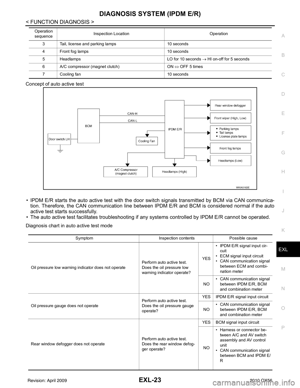
Concept of auto active test
• IPDM E/R starts the auto active test with the door
switch signals transmitted by BCM via CAN communica-
tion. Therefore, the CAN communication line between IPDM E/R and BCM is considered normal if the auto
active test starts successfully.
• The auto active test facilitates troubleshooting if any systems controlled by IPDM E/R cannot be operated.
Diagnosis chart in auto active test mode
3 Tail, license and parking lamps 10 seconds
4 Front fog lamps 10 seconds
5 Headlamps LO for 10 seconds → HI on-off for 5 seconds
6 A/C compressor (magnet clutch) ON ⇔ OFF 5 times
7 Cooling fan 10 seconds
Operation
sequence Inspection Location
Operation
WKIA5163E
SymptomInspection contentsPossible cause
Oil pressure low warning indicator does not operate Perform auto active test.
Does the oil pressure low
warning indicator operate?YES
• IPDM E/R signal input cir-
cuit
• ECM signal input circuit
• CAN communication signal
between ECM and combi-
nation meter
NO • CAN communication signal
between IPDM E/R, BCM
and combination meter
Oil pressure gauge does not operate Perform auto active test.
Does the oil pressure gauge
operate?YES IPDM E/R signal input circuit
NO • CAN communication signal
between IPDM E/R, BCM
and combination meter
Rear window defogger does not operate Perform auto active test.
Does the rear window defog-
ger operate?YES BCM signal input circuit
NO • Harness or connector be-
tween A/C and AV switch
assembly and AV control
unit
• CAN communication signal between BCM and IPDM E/
R
Revision: April 20092010 QX56
Page 2249 of 4210
GI-26
< PRECAUTION >
PRECAUTIONS
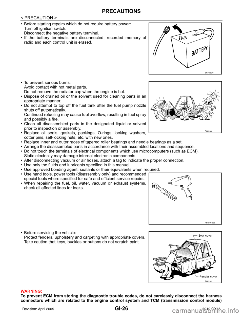
• Before starting repairs which do not require battery power:Turn off ignition switch.
Disconnect the negative battery terminal.
• If the battery terminals are disconnected, recorded memory of radio and each control unit is erased.
• To prevent serious burns: Avoid contact with hot metal parts.
Do not remove the radiator cap when the engine is hot.
• Dispose of drained oil or the solvent used for cleaning parts in an appropriate manner.
• Do not attempt to top off the fuel tank after the fuel pump nozzle
shuts off automatically.
Continued refueling may cause fuel overflow, resulting in fuel spray
and possibly a fire.
• Clean all disassembled parts in the designated liquid or solvent prior to inspection or assembly.
• Replace oil seals, gaskets, packings, O-rings, locking washers,
cotter pins, self-locking nuts, etc. with new ones.
• Replace inner and outer races of tapered roller bearings and needle bearings as a set.
• Arrange the disassembled parts in accordance with their assembled locations and sequence.
• Do not touch the terminals of electrical com ponents which use microcomputers (such as ECM).
Static electricity may damage internal electronic components.
• After disconnecting vacuum or air hoses, atta ch a tag to indicate the proper connection.
• Use only the fluids and lubricants specified in this manual.
• Use approved bonding agent, sealants or their equivalents when required.
• Use hand tools, power tools (disassembly only) and recommended special tools where specified for safe and efficient service repairs.
• When repairing the fuel, oil, water, vacuum or exhaust systems, check all affected lines for leaks.
• Before servicing the vehicle: Protect fenders, upholstery and carpeting with appropriate covers.
Take caution that keys, buckles or buttons do not scratch paint.
WARNING:
To prevent ECM from storing the diagnostic tro uble codes, do not carelessly disconnect the harness
connectors which are related to the engine control system and TCM (transmission control module)
SEF289H
SGI233
PBIC0190E
SGI234
Revision: April 20092010 QX56
Page 2650 of 4210
LAN-52
< COMPONENT DIAGNOSIS >[CAN]
CAN COMMUNICATION SYSTEM
COMPONENT DIAGNOSIS
CAN COMMUNICATION SYSTEM
Component Parts LocationINFOID:0000000005146466
1. ECM E16
2. IPDM E/R E122 3. ICC sensor E42
4. AV control unit M45 5. Combination meter M246. ABS actuator and electric unit (con-
trol unit) E125
7. Intelligent Key unit M70 8. BCM M189. Data link connector M22
10. Steering angle sensor M17 11. Driver seat control unit B202 12. ICC unit B13
13. Air bag diagnosis sensor unit M35 14. A/T assembly F9 15. A/C auto amp. M50
16. Transfer control unit E142
AWMIA0011ZZ
Revision: April 20092010 QX56
Page 2769 of 4210
MWI
METER SYSTEMMWI-7
< FUNCTION DIAGNOSIS >
C
DE
F
G H
I
J
K L
M B A
O P
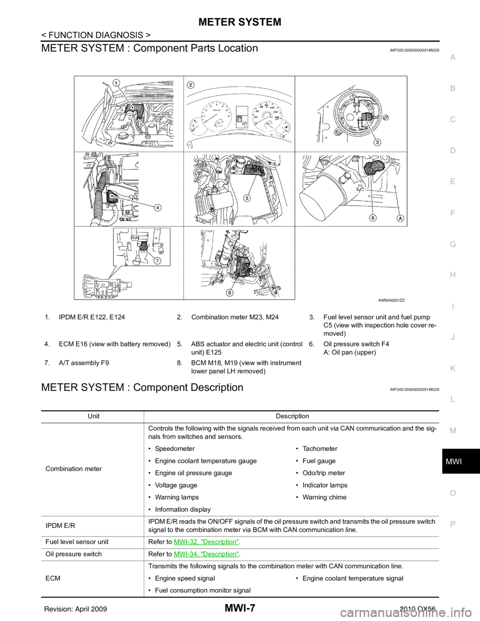
METER SYSTEM : Com ponent Parts LocationINFOID:0000000005146028
METER SYSTEM : Component DescriptionINFOID:0000000005146029
1. IPDM E/R E122, E124 2. Combination meter M23, M24 3. Fuel level sensor unit and fuel pump
C5 (view with inspection hole cover re-
moved)
4. ECM E16 (view with battery removed) 5. ABS actuator and electric unit (control unit) E1256. Oil pressure switch F4
A: Oil pan (upper)
7. A/T assembly F9 8. BCM M18, M19 (view with instrument
lower panel LH removed)
AWNIA0201ZZ
Unit Description
Combination meter Controls the following with the signals received from each unit via CAN communication and the sig-
nals from switches and sensors.
• Speedometer
• Tachometer
• Engine coolant temperature gauge • Fuel gauge
• Engine oil pressure gauge • Odo/trip meter
• Voltage gauge • Indicator lamps
• Warning lamps • Warning chime
• Information display
IPDM E/R IPDM E/R reads the ON/OFF signals of the oil pressure switch and transmits the oil pressure switch
signal to the combination meter via BCM with CAN communication line.
Fuel level sensor unit Refer to MWI-32, "
Description".
Oil pressure switch Refer to MWI-34, "
Description".
ECM Transmits the following signals to the combination meter with CAN communication line.
• Engine speed signal
• Engine coolant temperature signal
• Fuel consumption monitor signal
Revision: April 20092010 QX56
Page 2771 of 4210
MWI
METER SYSTEMMWI-9
< FUNCTION DIAGNOSIS >
C
DE
F
G H
I
J
K L
M B A
O P
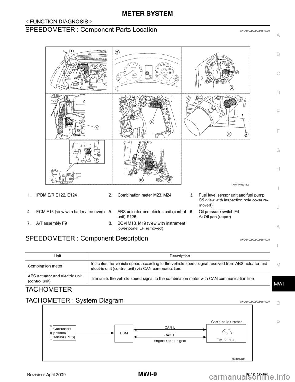
SPEEDOMETER : Compone nt Parts LocationINFOID:0000000005146032
SPEEDOMETER : Component DescriptionINFOID:0000000005146033
TACHOMETER
TACHOMETER : System DiagramINFOID:0000000005146034
1. IPDM E/R E122, E124 2. Combination meter M23, M24 3. Fuel level sensor unit and fuel pump
C5 (view with inspection hole cover re-
moved)
4. ECM E16 (view with battery removed) 5. ABS actuator and electric unit (control unit) E1256. Oil pressure switch F4
A: Oil pan (upper)
7. A/T assembly F9 8. BCM M18, M19 (view with instrument
lower panel LH removed)
AWNIA0201ZZ
Unit Description
Combination meter Indicates the vehicle speed according to the vehicle speed signal received from ABS actuator and
electric unit (control unit) via CAN communication.
ABS actuator and electric unit
(control unit) Transmits the vehicle speed signal to the combination meter with CAN communication line.
SKIB6904E
Revision: April 20092010 QX56
Page 2772 of 4210
MWI-10
< FUNCTION DIAGNOSIS >
METER SYSTEM
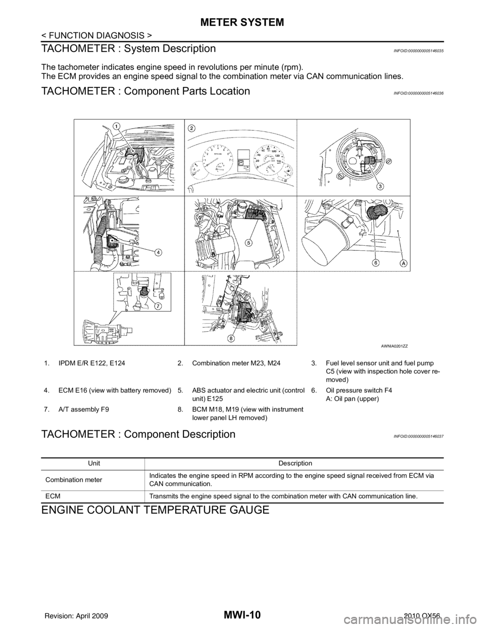
TACHOMETER : System Description
INFOID:0000000005146035
The tachometer indicates engine speed in revolutions per minute (rpm).
The ECM provides an engine speed signal to the co mbination meter via CAN communication lines.
TACHOMETER : Component Parts LocationINFOID:0000000005146036
TACHOMETER : Component DescriptionINFOID:0000000005146037
ENGINE COOLANT TEMPERATURE GAUGE
1. IPDM E/R E122, E1242. Combination meter M23, M24 3. Fuel level sensor unit and fuel pump
C5 (view with inspection hole cover re-
moved)
4. ECM E16 (view with battery removed) 5. ABS actuator and electric unit (control
unit) E125 6. Oil pressure switch F4
A: Oil pan (upper)
7. A/T assembly F9 8. BCM M18, M19 (view with instrument
lower panel LH removed)
AWNIA0201ZZ
Unit Description
Combination meter Indicates the engine speed in RPM according to the engine speed signal received from ECM via
CAN communication.
ECM Transmits the engine speed signal to the combination meter with CAN communication line.
Revision: April 20092010 QX56
Page 2773 of 4210
MWI
METER SYSTEMMWI-11
< FUNCTION DIAGNOSIS >
C
DE
F
G H
I
J
K L
M B A
O P
ENGINE COOLANT TEMPERATURE GAUGE : System DiagramINFOID:0000000005146038
ENGINE COOLANT TEMPERATURE GAUGE : System DescriptionINFOID:0000000005146039
The engine coolant temperature gauge indicates the engine coolant temperature.
The ECM provides an engine coolant temperature signal to the combination meter via CAN communication
lines.
ENGINE COOLANT TEMPERATURE GA UGE : Component Parts Location
INFOID:0000000005146040
SKIB6905E
1. IPDM E/R E122, E124 2. Combination meter M23, M24 3. Fuel level sensor unit and fuel pump
C5 (view with inspection hole cover re-
moved)
4. ECM E16 (view with battery removed) 5. ABS actuator and electric unit (control unit) E1256. Oil pressure switch F4
A: Oil pan (upper)
7. A/T assembly F9 8. BCM M18, M19 (view with instrument
lower panel LH removed)
AWNIA0201ZZ
Revision: April 20092010 QX56
Page 2774 of 4210
MWI-12
< FUNCTION DIAGNOSIS >
METER SYSTEM
ENGINE COOLANT TEMPERATURE GAUGE : Component Description
INFOID:0000000005146041
FUEL GAUGE
FUEL GAUGE : System DiagramINFOID:0000000005146042
FUEL GAUGE : System DescriptionINFOID:0000000005146043
The fuel gauge indicates the approximate fuel level in the fuel tank.
The fuel gauge is regulated by the unified meter control unit and a variable resistor signal supplied by the fuel
level sensor unit.
FUEL GAUGE : Compone nt Parts LocationINFOID:0000000005146044
Unit Description
Combination meter Indicates the engine coolant temperature according to the engine coolant temperature signal re-
ceived from ECM via CAN communication.
ECM Transmits the engine coolant temperature signal to the combination meter via CAN communication.
AWNIA0004GB
AWNIA0201ZZ
Revision: April 20092010 QX56