2010 INFINITI QX56 ecm location
[x] Cancel search: ecm locationPage 2776 of 4210
MWI-14
< FUNCTION DIAGNOSIS >
METER SYSTEM
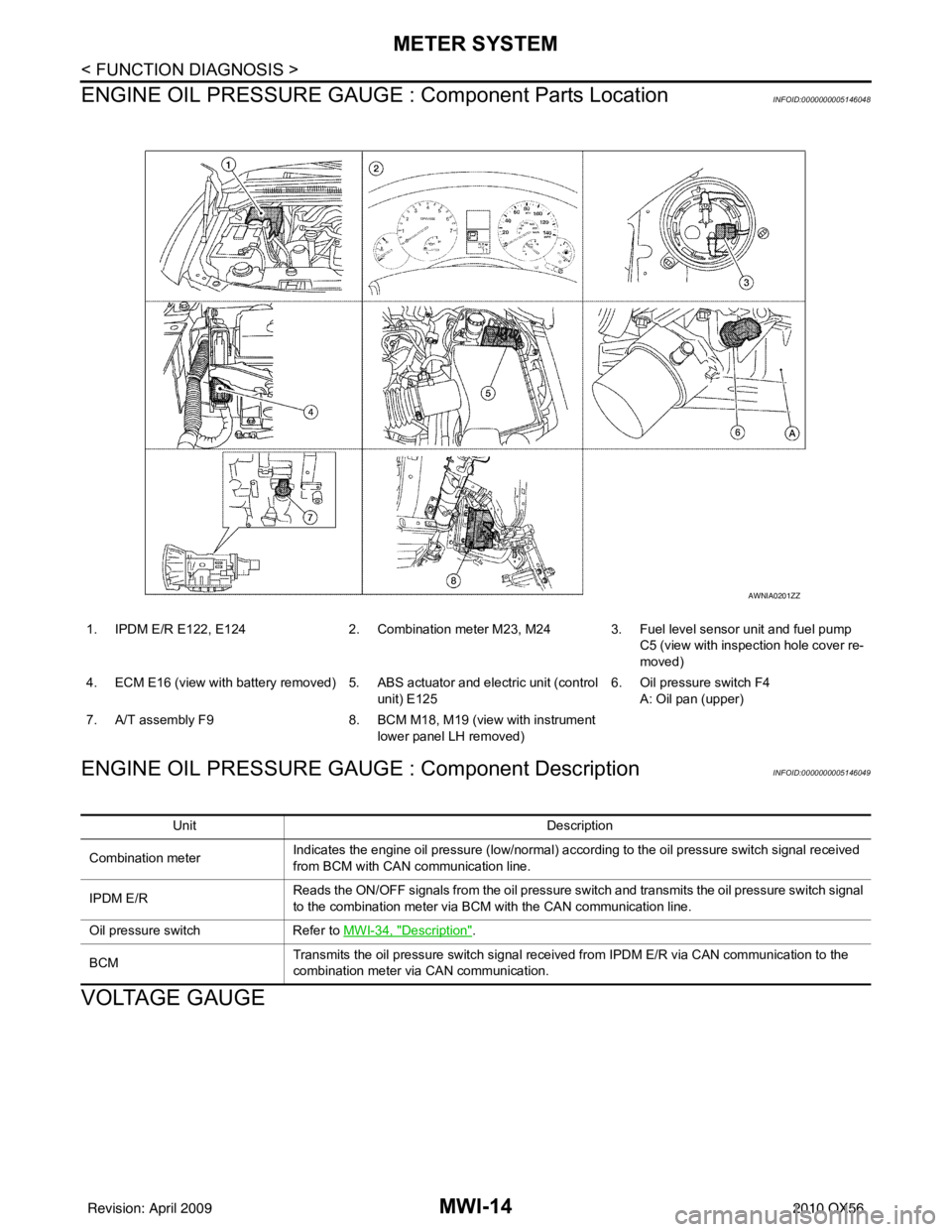
ENGINE OIL PRESSURE GAUGE : Component Parts Location
INFOID:0000000005146048
ENGINE OIL PRESSURE GAUGE : Component DescriptionINFOID:0000000005146049
VOLTAGE GAUGE
1. IPDM E/R E122, E124 2. Combination meter M23, M24 3. Fuel level sensor unit and fuel pump
C5 (view with inspection hole cover re-
moved)
4. ECM E16 (view with battery removed) 5. ABS actuator and electric unit (control
unit) E125 6. Oil pressure switch F4
A: Oil pan (upper)
7. A/T assembly F9 8. BCM M18, M19 (view with instrument
lower panel LH removed)
AWNIA0201ZZ
Unit Description
Combination meter Indicates the engine oil pressure (low/normal) according to the oil pressure switch signal received
from BCM with CAN
communication line.
IPDM E/R Reads the ON/OFF signals from the oil pressure switch and transmits the oil pressure switch signal
to the combination meter via BCM with the CAN communication line.
Oil pressure switch Refer to MWI-34, "
Description".
BCM Transmits the oil pressure switch signal received from IPDM E/R via CAN communication to the
combination meter via CAN communication.
Revision: April 20092010 QX56
Page 2777 of 4210
MWI
METER SYSTEMMWI-15
< FUNCTION DIAGNOSIS >
C
DE
F
G H
I
J
K L
M B A
O P
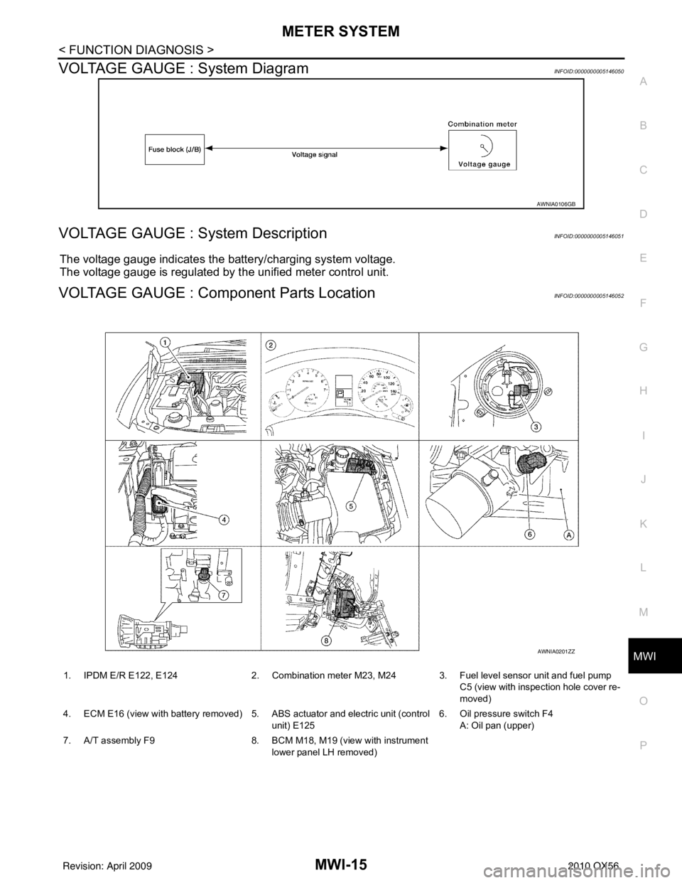
VOLTAGE GAUGE : System DiagramINFOID:0000000005146050
VOLTAGE GAUGE : System DescriptionINFOID:0000000005146051
The voltage gauge indicates the battery/charging system voltage.
The voltage gauge is regulated by the unified meter control unit.
VOLTAGE GAUGE : Component Parts LocationINFOID:0000000005146052
AWNIA0106GB
1. IPDM E/R E122, E124 2. Combination meter M23, M24 3. Fuel level sensor unit and fuel pump
C5 (view with inspection hole cover re-
moved)
4. ECM E16 (view with battery removed) 5. ABS actuator and electric unit (control unit) E1256. Oil pressure switch F4
A: Oil pan (upper)
7. A/T assembly F9 8. BCM M18, M19 (view with instrument
lower panel LH removed)
AWNIA0201ZZ
Revision: April 20092010 QX56
Page 2780 of 4210
MWI-18
< FUNCTION DIAGNOSIS >
METER SYSTEM
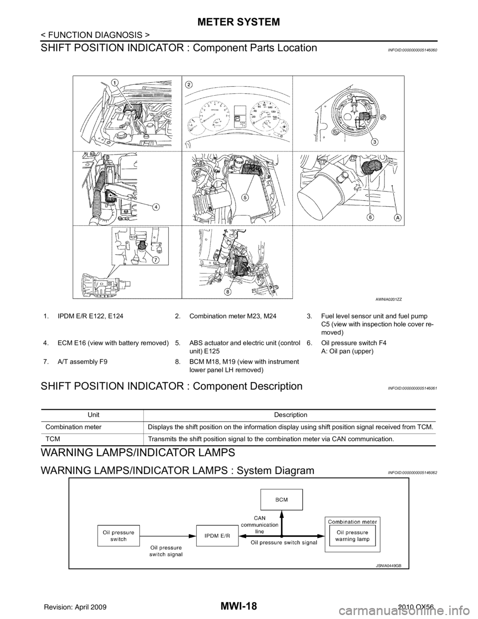
SHIFT POSITION INDICATOR : Component Parts Location
INFOID:0000000005146060
SHIFT POSITION INDICATOR : Component DescriptionINFOID:0000000005146061
WARNING LAMPS/INDICATOR LAMPS
WARNING LAMPS/INDICATOR LAMPS : System DiagramINFOID:0000000005146062
1. IPDM E/R E122, E124 2. Combination meter M23, M24 3. Fuel level sensor unit and fuel pump
C5 (view with inspection hole cover re-
moved)
4. ECM E16 (view with battery removed) 5. ABS actuator and electric unit (control
unit) E125 6. Oil pressure switch F4
A: Oil pan (upper)
7. A/T assembly F9 8. BCM M18, M19 (view with instrument
lower panel LH removed)
AWNIA0201ZZ
Unit Description
Combination meter Displays the shift position on the information display using shift position signal received from TCM.
TCM Transmits the shift position signal to the combination meter via CAN communication.
JSNIA0449GB
Revision: April 20092010 QX56
Page 2781 of 4210
MWI
METER SYSTEMMWI-19
< FUNCTION DIAGNOSIS >
C
DE
F
G H
I
J
K L
M B A
O P
WARNING LAMPS/INDICATOR LAMPS : System DescriptionINFOID:0000000005146063
OIL PRESSURE WARNING LAMP
• IPDM E/R reads the ON/OFF signals from the oil pressure switch and transmits the oil pressure switch sig-
nal to the combination meter via BCM with the CAN communication line.
• The combination meter turns the oil pressure warning lamp ON/OFF according to the oil pressure switch sig- nal received via CAN communication.
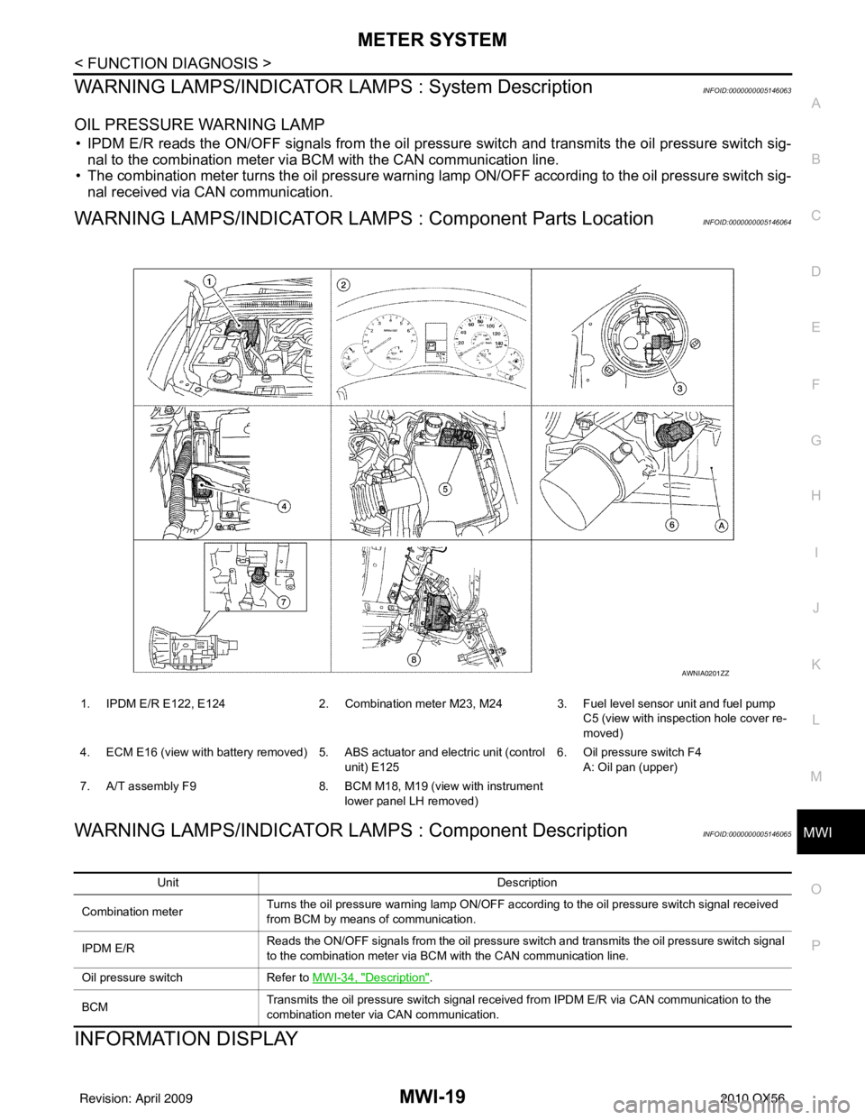
WARNING LAMPS/INDICATOR LAMPS : Component Parts LocationINFOID:0000000005146064
WARNING LAMPS/INDICATOR LAMPS : Component DescriptionINFOID:0000000005146065
INFORMATION DISPLAY
1. IPDM E/R E122, E124 2. Combination meter M23, M24 3. Fuel level sensor unit and fuel pump
C5 (view with inspection hole cover re-
moved)
4. ECM E16 (view with battery removed) 5. ABS actuator and electric unit (control unit) E1256. Oil pressure switch F4
A: Oil pan (upper)
7. A/T assembly F9 8. BCM M18, M19 (view with instrument
lower panel LH removed)
AWNIA0201ZZ
Unit Description
Combination meter Turns the oil pressure warning lamp ON/OFF according to the oil pressure switch signal received
from BCM by means of communication.
IPDM E/R Reads the ON/OFF signals from the oil pressure switch and transmits the oil pressure switch signal
to the combination meter via BCM with the CAN communication line.
Oil pressure switch Refer to MWI-34, "
Description".
BCM Transmits the oil pressure switch signal received from IPDM E/R via CAN communication to the
combination meter via CAN communication.
Revision: April 20092010 QX56
Page 2783 of 4210
MWI
METER SYSTEMMWI-21
< FUNCTION DIAGNOSIS >
C
DE
F
G H
I
J
K L
M B A
O P
INFORMATION DISPLAY : Co mponent Parts LocationINFOID:0000000005146068
INFORMATION DISPLAY : Component DescriptionINFOID:0000000005146069
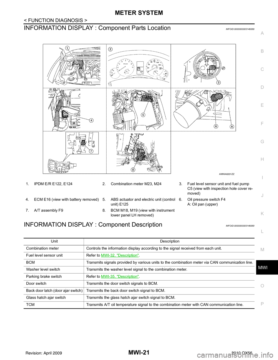
1. IPDM E/R E122, E124 2. Combination meter M23, M24 3. Fuel level sensor unit and fuel pump
C5 (view with inspection hole cover re-
moved)
4. ECM E16 (view with battery removed) 5. ABS actuator and electric unit (control unit) E1256. Oil pressure switch F4
A: Oil pan (upper)
7. A/T assembly F9 8. BCM M18, M19 (view with instrument
lower panel LH removed)
AWNIA0201ZZ
Unit Description
Combination meter Controls the information display according to the signal received from each unit.
Fuel level sensor unit Refer to MWI-32, "
Description".
BCM Transmits signals provided by various units to the combination meter via CAN communication line.
Washer level switch Transmits the washer level signal to the combination meter.
Parking brake switch Refer to MWI-35, "
Description".
Door switch Transmits the door switch signals to BCM.
Back door latch (door ajar switch) Transmits the back door switch signal to BCM.
Glass hatch ajar switch Transmits the glass hatch ajar switch signal to BCM.
TCM Transmits A/T oil temperature signal to the combination meter with CAN communication line.
Revision: April 20092010 QX56
Page 2888 of 4210
![INFINITI QX56 2010 Factory Service Manual PCS
DIAGNOSIS SYSTEM (IPDM E/R)PCS-13
< FUNCTION DIAGNOSIS > [IPDM E/R]
C
D
E
F
G H
I
J
K L
B A
O P
N
Concept of auto active test
• IPDM E/R starts the auto active test with the door
switch signals INFINITI QX56 2010 Factory Service Manual PCS
DIAGNOSIS SYSTEM (IPDM E/R)PCS-13
< FUNCTION DIAGNOSIS > [IPDM E/R]
C
D
E
F
G H
I
J
K L
B A
O P
N
Concept of auto active test
• IPDM E/R starts the auto active test with the door
switch signals](/manual-img/42/57032/w960_57032-2887.png)
PCS
DIAGNOSIS SYSTEM (IPDM E/R)PCS-13
< FUNCTION DIAGNOSIS > [IPDM E/R]
C
D
E
F
G H
I
J
K L
B A
O P
N
Concept of auto active test
• IPDM E/R starts the auto active test with the door
switch signals transmitted by BCM via CAN communica-
tion. Therefore, the CAN communication line between IPDM E/R and BCM is considered normal if the auto
active test starts successfully.
• The auto active test facilitates troubleshooting if any systems controlled by IPDM E/R cannot be operated.
Diagnosis chart in auto active test mode
3 Tail, license and parking lamps 10 seconds
4 Front fog lamps 10 seconds
5 Headlamps LO for 10 seconds → HI on-off for 5 seconds
6 A/C compressor (magnet clutch) ON ⇔ OFF 5 times
7 Cooling fan 10 seconds
Operation
sequence Inspection Location
Operation
WKIA5163E
SymptomInspection contentsPossible cause
Oil pressure low warning indicator does not operate Perform auto active test.
Does the oil pressure low
warning indicator operate?YES
• IPDM E/R signal input cir-
cuit
• ECM signal input circuit
• CAN communication signal
between ECM and combi-
nation meter
NO • CAN communication signal
between IPDM E/R, BCM
and combination meter
Oil pressure gauge does not operate Perform auto active test.
Does the oil pressure gauge
operate?YES IPDM E/R signal input circuit
NO • CAN communication signal
between IPDM E/R, BCM
and combination meter
Rear window defogger does not operate Perform auto active test.
Does the rear window defog-
ger operate?YES BCM signal input circuit
NO • Harness or connector be-
tween A/C and AV switch
assembly and AV control
unit
• CAN communication signal between BCM and IPDM E/
R
Revision: April 20092010 QX56
Page 3352 of 4210
SEC-1
BODY EXTERIOR, DOORS, ROOF & VEHICLE SECURITY
C
DE
F
G H
I
J
L
M
SECTION SEC
A
B
SEC
N
O P
CONTENTS
SECURITY CONTROL SYSTEM
WITH INTELLIGENT KEY SYSTEM
BASIC INSPECTION ....... .............................
4
DIAGNOSIS AND REPAIR WORKFLOW ..... .....4
Work Flow ........................................................... ......4
PRE-INSPECTION FOR DIAGNOSTIC ..............7
Basic Inspection .................................................. ......7
Vehicle Security Operation Check ............................7
INSPECTION AND ADJUSTMENT .....................9
ADDITIONAL SERVICE WHEN REPLACING
CONTROL UNIT .................................................... ......
9
ADDITIONAL SERVICE WHEN REPLACING
CONTROL UNIT : Special Repair Requirement .......
9
ECM RE-COMMUNICATING FUNCTION ............. ......9
ECM RE-COMMUNICATING FUNCTION : De-
scription .....................................................................
9
ECM RE-COMMUNICATING FUNCTION : Spe-
cial Repair Requirement ............................................
9
FUNCTION DIAGNOSIS ..............................10
INTELLIGENT KEY SYSTEM/ENGINE
START FUNCTIO N ........................................ ....
10
System Diagram .................................................. ....10
System Description .................................................10
Component Parts Location ......................................12
Component Description ...........................................13
INFINITI VEHICLE IMMOBILIZER SYSTEM-
NATS ..................................................................
14
System Diagram .................................................. ....14
System Description .................................................14
Component Parts Location ......................................16
Component Description ..........................................16
VEHICLE SECURITY SYSTEM .........................18
System Diagram .................................................. ....18
System Description .................................................18
Component Parts Location .................................. ....19
Component Description ...........................................20
DIAGNOSIS SYSTEM (BCM) ...........................21
COMMON ITEM ..................................................... ....21
COMMON ITEM : CONSULT-III Function (BCM -
COMMON ITEM) .....................................................
21
IMMU ...................................................................... ....21
IMMU : CONSULT-III Function (BCM - IMMU) ........22
THEFT ALM ........................................................... ....22
THEFT ALM : CONSULT-III Function (BCM -
THEFT ALM) ....................................................... ....
22
DIAGNOSIS SYSTEM (INTELLIGENT KEY
UNIT) .................................................................
24
CONSULT-III Function (INTELLIGENT KEY) ..........24
COMPONENT DIAGNOSIS .........................26
U1000 CAN COMM CIRCUIT ...........................26
Description ........................................................... ....26
DTC Logic ................................................................26
Diagnosis Procedure ...............................................26
U1010 CONTROL UNIT (CAN) .........................27
Description ...............................................................27
DTC Logic ................................................................27
Diagnosis Procedure ...............................................27
Special Repair Requirement ....................................27
B2013 ID DISCORD I-KEY-STRG ....................28
Description ...............................................................28
DTC Logic ................................................................28
Diagnosis Procedure ...............................................28
B2190 NATS ANTENNA AMP. .........................31
Description ...............................................................31
DTC Logic ................................................................31
Diagnosis Procedure ...............................................31
Revision: April 20092010 QX56
Page 3363 of 4210
![INFINITI QX56 2010 Factory Service Manual SEC-12
< FUNCTION DIAGNOSIS >[WITH INTELLIGENT KEY SYSTEM]
INTELLIGENT KEY SYSTEM/ENGINE START FUNCTION
Component Parts Location
INFOID:0000000005147069
ALKIA0958ZZ
1. BCM M18, M20 (view with instrume INFINITI QX56 2010 Factory Service Manual SEC-12
< FUNCTION DIAGNOSIS >[WITH INTELLIGENT KEY SYSTEM]
INTELLIGENT KEY SYSTEM/ENGINE START FUNCTION
Component Parts Location
INFOID:0000000005147069
ALKIA0958ZZ
1. BCM M18, M20 (view with instrume](/manual-img/42/57032/w960_57032-3362.png)
SEC-12
< FUNCTION DIAGNOSIS >[WITH INTELLIGENT KEY SYSTEM]
INTELLIGENT KEY SYSTEM/ENGINE START FUNCTION
Component Parts Location
INFOID:0000000005147069
ALKIA0958ZZ
1. BCM M18, M20 (view with instrument panel LH removed) 2. Intelligent Key unit M70
(view with instrument panel LH removed) 3. IPDM E/R
E119, E120, E122, E124
4. ECM E16 5. Key switch and ignition knob switch M12
(view with steering column removed) 6. Steering lock solenoid M15
7. Remote keyless entry receiver M25 (view with instrume nt panel RH removed) 8. A/T shift selector (park position switch)
M203
(view with center console removed) 9. Center console area antenna
(front) M210
(view with center console removed)
Revision: April 20092010 QX56