Page 4139 of 4210
WW-18
< COMPONENT DIAGNOSIS >
WIPER AND WASHER FUSE
COMPONENT DIAGNOSIS
WIPER AND WASHER FUSE
DescriptionINFOID:0000000005146770
Fuse list
Diagnosis ProcedureINFOID:0000000005146771
1. CHECK FUSES
Check that the following fuses are not blown.
Is the fuse blown?
YES >> Replace the fuse after repairing the applicable circuit.
NO >> The fuse is normal.
Unit LocationFuse No. Capacity
Front wiper motor IPDM E/R3930 A
Front and rear washer motor Fuse block (J/B)910 A
Unit LocationFuse No. Capacity
Front wiper motor IPDM E/R3930 A
Front and rear washer motor Fuse block (J/B)910 A
Revision: April 20092010 QX56
Page 4140 of 4210

FRONT WIPER MOTOR LO CIRCUITWW-19
< COMPONENT DIAGNOSIS >
C
DE
F
G H
I
J
K
M A
B
WW
N
O P
FRONT WIPER MOTOR LO CIRCUIT
Component Function CheckINFOID:0000000005146772
1. CHECK FRONT WIPER LO OPERATION
IPDM E/R AUTO ACTIVE TEST
1. Start IPDM E/R auto active test. Refer to PCS-12, "
Diagnosis Description".
2. Check that the front wiper operates at the LO operation.
CONSULT-III ACTIVE TEST
1. Select "FRONT WIPER" of IPDM E/R active test item.
2. While operating the test item, check front wiper operation.
Is front wiper (LO) operation normal?
YES >> Front wiper motor LO circuit is normal.
NO >> Refer to WW-19, "
Diagnosis Procedure".
Diagnosis ProcedureINFOID:0000000005146773
Regarding Wiring Diagram information, refer to WW-31, "Wiring Diagram".
1. CHECK FRONT WIPER MOTOR FUSE
1. Turn the ignition switch OFF.
2. Check that the following fuse is not blown.
Is the fuse blown?
YES >> GO TO 2
NO >> GO TO 3
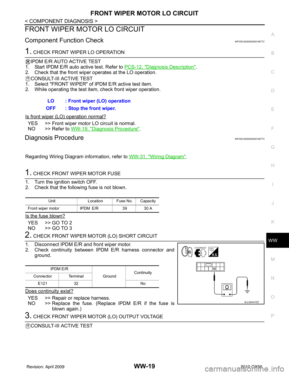
2. CHECK FRONT WIPER MOTOR (LO) SHORT CIRCUIT
1. Disconnect IPDM E/R and front wiper motor.
2. Check continuity between IPDM E/R harness connector and ground.
Does continuity exist?
YES >> Repair or replace harness.
NO >> Replace the fuse. (Replace IPDM E/R if the fuse is blown again.)
3. CHECK FRONT WIPER MOTOR (LO) OUTPUT VOLTAGE
CONSULT-III ACTIVE TEST LO : Front wiper (LO) operation
OFF : Stop the front wiper.
Unit Location Fuse No. Capacity
Front wiper motor IPDM E/R39 30 A
IPDM E/R
GroundContinuity
Connector Terminal
E121 32 No
ALLIA0447ZZ
Revision: April 20092010 QX56
Page 4142 of 4210

FRONT WIPER MOTOR HI CIRCUITWW-21
< COMPONENT DIAGNOSIS >
C
DE
F
G H
I
J
K
M A
B
WW
N
O P
FRONT WIPER MOTOR HI CIRCUIT
Component Function CheckINFOID:0000000005146774
1. CHECK FRONT WIPER HI OPERATION
IPDM E/R AUTO ACTIVE TEST
1. Start IPDM E/R auto active test. Refer to PCS-12, "
Diagnosis Description".
2. Check that the front wiper operates at the HI operation.
CONSULT-III ACTIVE TEST
1. Select "FRONT WIPER" of IPDM E/R active test item.
2. While operating the test item, check front wiper operation.
Is front wiper (HI) operation normal?
YES >> Front wiper motor HI circuit is normal.
NO >> Refer to WW-21, "
Diagnosis Procedure".
Diagnosis ProcedureINFOID:0000000005146775
Regarding Wiring Diagram information, refer to WW-31, "Wiring Diagram".
1. CHECK FRONT WIPER MOTOR FUSE
1. Turn the ignition switch OFF.
2. Check that the following fuse is not blown.
Is the fuse blown?
YES >> GO TO 2
NO >> GO TO 3
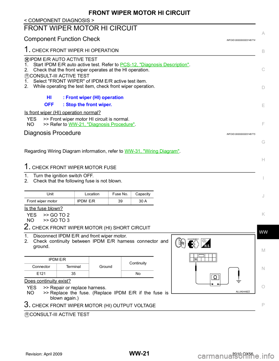
2. CHECK FRONT WIPER MOTOR (HI) SHORT CIRCUIT
1. Disconnect IPDM E/R and front wiper motor.
2. Check continuity between IPDM E/R harness connector and ground.
Does continuity exist?
YES >> Repair or replace harness.
NO >> Replace the fuse. (Replace IPDM E/R if the fuse is blown again.)
3. CHECK FRONT WIPER MOTOR (HI) OUTPUT VOLTAGE
CONSULT-III ACTIVE TEST HI : Front wiper (HI) operation
OFF : Stop the front wiper.
Unit Location Fuse No. Capacity
Front wiper motor IPDM E/R39 30 A
IPDM E/R
GroundContinuity
Connector Terminal
E121 35 No
ALLIA0448ZZ
Revision: April 20092010 QX56
Page 4182 of 4210

IPDM E/R (INTELLIGENT POWER DISTRIBUTION MODULE ENGINE ROOM)
WW-61
< ECU DIAGNOSIS >
C
D E
F
G H
I
J
K
M A
B
WW
N
O P
Te r m i n a l Wire
color Signal name Signal
input/
output Measuring condition
Reference value(Approx.)
Igni-
tion
switch Operation or condition
1 B/Y Battery power supply Input OFF —Battery voltage
2 R Battery power supply Input OFF —Battery voltage
3BRECM relay Output— Ignition switch ON or START
Battery voltage
Ignition switch OFF or ACC 0V
4W/LECM relay Output— Ignition switch ON or START
Battery voltage
Ignition switch OFF or ACC 0V
6L Throttle control motor
relay Output —Ignition switch ON or START
Battery voltage
Ignition switch OFF or ACC 0V
7 W/B ECM relay control Input — Ignition switch ON or START
0V
Ignition switch OFF or ACC Battery voltage
8 R/B Fuse 54 Output —Ignition switch ON or START
Battery voltage
Ignition switch OFF or ACC 0V
10 G Fuse 45
(Canada only) Output ONDaytime light system active
0V
Daytime light system inactive Battery voltage
11 Y/B A/C compressor Output ON or
START A/C switch ON or defrost A/C
switch
Battery voltage
A/C switch OFF or defrost A/C
switch 0V
12 L/W Ignition switch sup-
plied power Input —OFF or ACC
0V
ON or START Battery voltage
13 B/Y Fuel pump relay Output — Ignition switch ON or START
Battery voltage
Ignition switch OFF or ACC 0V
14 Y/R Fuse 49 Output —Ignition switch ON or START
Battery voltage
Ignition switch OFF or ACC 0V
15 LG/B Fuse 50 Output —Ignition switch ON or START
Battery voltage
Ignition switch OFF or ACC 0V
16 G Fuse 51 Output —Ignition switch ON or START
Battery voltage
Ignition switch OFF or ACC 0V
17 W Fuse 55 Output —Ignition switch ON or START
Battery voltage
Ignition switch OFF or ACC 0V
19 W/R Starter motor Output START—Battery voltage
21 BR Ignition switch sup-
plied power
Input —OFF or ACC
0V
START Battery voltage
22 G Battery power supply Output OFF —Battery voltage
23 GR/W Door mirror defogger
output signal Output —When rear defogger switch is
ON
Battery voltage
When raker defogger switch is
OFF 0V
24 L Cooling fan relay Output — Conditions correct for cooling
fan operation
Battery voltage
Conditions not correct for
cooling fan operation 0V
Revision: April 20092010 QX56
Page 4183 of 4210

WW-62
< ECU DIAGNOSIS >
IPDM E/R (INTELLIGENT POWER DISTRIBUTION MODULE ENGINE ROOM)
26 P/LHeadlamp aiming mo-
tors
Output —Lighting
switch 2nd
position or
AUTO, head-
lamp aiming
switch in po-
sition OFF
0V
ON Battery voltage
27 W/B Fuse 38
(With trailer tow)
Output —Ignition switch ON or START
Battery voltage
Ignition switch OFF or ACC 0V
30 W Fuse 53 Output —Ignition switch ON or START
Battery voltage
Ignition switch OFF or ACC 0V
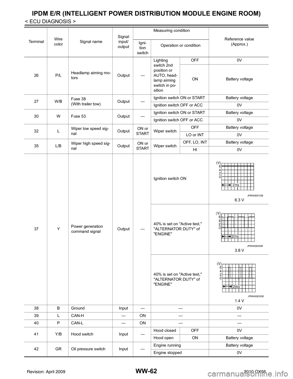
32 L Wiper low speed sig-
nal
OutputON or
START Wiper switch OFF
Battery voltage
LO or INT 0V
35 L/B Wiper high speed sig-
nal
OutputON or
START Wiper switch OFF, LO, INT Battery voltage
HI 0V
37 Y Power generation
command signal Output —Ignition switch ON
6.3 V
40% is set on "Active test,"
"ALTERNATOR DUTY" of
"ENGINE" 3.8 V
40% is set on "Active test,"
"ALTERNATOR DUTY" of
"ENGINE" 1.4 V
38 B Ground Input ——0V
39 L CAN-H — ON— —
40 P CAN-L — ON— —
41 Y/B Hood switch Input —Hood closed OFF
0V
Hood open ON Battery voltage
42 GR Oil pressure switch Input — Engine running
Battery voltage
Engine stopped 0V
Te r m i n a l
Wire
color Signal name Signal
input/
output Measuring condition
Reference value(Approx.)
Igni-
tion
switch Operation or condition
JPMIA0001GB
JPMIA0002GB
JPMIA0003GB
Revision: April 20092010 QX56
Page 4185 of 4210
WW-64
< ECU DIAGNOSIS >
IPDM E/R (INTELLIGENT POWER DISTRIBUTION MODULE ENGINE ROOM)
*: When horn reminder is ON60 B/W
Rear window defog-
ger relay
OutputON or
START Rear defogger switch ON
Battery voltage
Rear defogger switch OFF 0V
61 BR Fuse 32
(With trailer tow) Output OFF
—Battery voltage
Te r m i n a l
Wire
color Signal name Signal
input/
output Measuring condition
Reference value(Approx.)
Igni-
tion
switch Operation or condition
Revision: April 20092010 QX56
Page 4196 of 4210

FRONT WIPER DOES NOT OPERATEWW-75
< SYMPTOM DIAGNOSIS >
C
DE
F
G H
I
J
K
M A
B
WW
N
O P
FRONT WIPER DO ES NOT OPERATE
DescriptionINFOID:0000000005146798
The front wiper does not operate under any operation conditions.
Diagnosis ProcedureINFOID:0000000005146799
Regarding Wiring Diagram information, refer to WW-31, "Wiring Diagram".
1. CHECK WIPER RELAY OPERATION
IPDM E/R AUTO ACTIVE TEST
1. Start IPDM E/R auto active test. Refer to PCS-8, "
System Description".
2. Check that the front wiper operates at the LO/HI operation.
CONSULT-III ACTIVE TEST
1. Select "FRONT WIPER" of IPDM E/R active test item.
2. While operating the test item, check front wiper operation.
Is front wiper operation normal?
YES >> GO TO 5
NO >> GO TO 2
2. CHECK FRONT WIPER MOTOR FUSE
1. Turn the ignition switch OFF.
2. Check that the following fuse is not blown.
Is the fuse blown?
YES >> Replace the fuse after repairing the applicable circuit.
NO >> GO TO 3
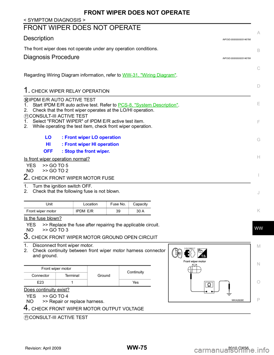
3. CHECK FRONT WIPER MOTOR GROUND OPEN CIRCUIT
1. Disconnect front wiper motor.
2. Check continuity between front wiper motor harness connector and ground.
Does continuity exist?
YES >> GO TO 4
NO >> Repair or replace harness.
4. CHECK FRONT WIPER MOTOR OUTPUT VOLTAGE
CONSULT-III ACTIVE TEST LO : Front wiper LO operation
HI : Front wiper HI operation
OFF : Stop the front wiper.
Unit Location Fuse No. Capacity
Front wiper motor IPDM E/R39 30 A
Front wiper motor
GroundContinuity
Connector Terminal
E23 1 Yes
WKIA2828E
Revision: April 20092010 QX56