2010 INFINITI QX56 wiper
[x] Cancel search: wiperPage 3464 of 4210
![INFINITI QX56 2010 Factory Service Manual IPDM E/R (INTELLIGENT POWER DISTRIBUTION MODULE ENGINE ROOM)
SEC-113
< ECU DIAGNOSIS > [WITH INTELLIGENT KEY SYSTEM]
C
D
E
F
G H
I
J
L
M A
B
SEC
N
O P
*: When horn reminder is ON
Fail SafeINFOID:00000 INFINITI QX56 2010 Factory Service Manual IPDM E/R (INTELLIGENT POWER DISTRIBUTION MODULE ENGINE ROOM)
SEC-113
< ECU DIAGNOSIS > [WITH INTELLIGENT KEY SYSTEM]
C
D
E
F
G H
I
J
L
M A
B
SEC
N
O P
*: When horn reminder is ON
Fail SafeINFOID:00000](/manual-img/42/57032/w960_57032-3463.png)
IPDM E/R (INTELLIGENT POWER DISTRIBUTION MODULE ENGINE ROOM)
SEC-113
< ECU DIAGNOSIS > [WITH INTELLIGENT KEY SYSTEM]
C
D
E
F
G H
I
J
L
M A
B
SEC
N
O P
*: When horn reminder is ON
Fail SafeINFOID:0000000005282721
CAN COMMUNICATION CONTROL
When CAN communication with ECM and BCM is impossible, IPDM E/R performs fail-s afe control. After CAN
communication recovers normally, it also returns to normal control.
If No CAN Communication Is Available With ECM
If No CAN Communication Is Available With BCM
IGNITION RELAY MALFUNCTION DETECTION FUNCTION
• IPDM E/R monitors the voltage at the contact circuit and excitation coil circuit of the ignition relay inside it.
• IPDM E/R judges the ignition relay error if the voltage differs between the contact circuit and the excitation coil circuit.
• If the ignition relay cannot turn OFF due to contact seizure, it activates the tail lamp relay for 10 minutes to
alert the user to the ignition relay malfunction when the ignition switch is turned OFF.
NOTE:
The tail lamp turns OFF when the ignition switch is turned ON.
FRONT WIPER CONTROL
IPDM E/R detects front wiper stop posit ion by a front wiper auto stop signal.
60 B/WRear window defog-
ger relay
OutputON or
START Rear defogger switch ON
Battery voltage
Rear defogger switch OFF 0V
61 BR Fuse 32
(With trailer tow) Output OFF
—Battery voltage
Te r m i n a l
Wire
color Signal name Signal
input/
output Measuring condition
Reference value(Approx.)
Igni-
tion
switch Operation or condition
Control part
Fail-safe in operation
Cooling fan • Turns ON the cooling fan relay when the ignition switch is turned ON
• Turns OFF the cooling fan relay when the ignition switch is turned OFF
Control part
Fail-safe in operation
Headlamp • Turns ON the headlamp low relay when the ignition switch is turned ON
• Turns OFF the headlamp low relay when the ignition switch is turned OFF
• Headlamp high LH/RH relays OFF
•Parking lamps
• License plate lamps
• Tail lamps • Turns ON the tail lamp relay when the ignition switch is turned ON
• Turns OFF the tail lamp relay when the ignition switch is turned OFF
Front wiper • The status just before activation of fail-safe control is maintained until the ignition
switch is turned OFF while the front wiper is operating at LO or HI speed.
• The wiper is operated at LO speed until the ignition switch is turned OFF if the fail-
safe control is activated while the front wipe r is set in the INT mode and the front wiper
motor is operating.
Rear window defogger Rear window defogger relay OFF
A/C compressor A/C relay OFF
Front fog lamps Front fog lamp relay OFF
Ignition switch Ignition relayTail lamp relay
ON ON —
OFF OFF —
Revision: April 20092010 QX56
Page 3465 of 4210
![INFINITI QX56 2010 Factory Service Manual SEC-114
< ECU DIAGNOSIS >[WITH INTELLIGENT KEY SYSTEM]
IPDM E/R (INTELLIGENT POWER DI
STRIBUTION MODULE ENGINE ROOM)
When a front wiper auto stop signal is in the conditions listed below, IPDM E/R st INFINITI QX56 2010 Factory Service Manual SEC-114
< ECU DIAGNOSIS >[WITH INTELLIGENT KEY SYSTEM]
IPDM E/R (INTELLIGENT POWER DI
STRIBUTION MODULE ENGINE ROOM)
When a front wiper auto stop signal is in the conditions listed below, IPDM E/R st](/manual-img/42/57032/w960_57032-3464.png)
SEC-114
< ECU DIAGNOSIS >[WITH INTELLIGENT KEY SYSTEM]
IPDM E/R (INTELLIGENT POWER DI
STRIBUTION MODULE ENGINE ROOM)
When a front wiper auto stop signal is in the conditions listed below, IPDM E/R stops power supply to wiper
after repeating a front wiper 10 second activation and 20 second stop five times.
NOTE:
This operation status can be confirmed on the IPDM E/R “DATA MONITOR” that displays “Block” for the item
“WIP PROT” while the wiper is stopped.
STARTER MOTOR PROTECTION FUNCTION
IPDM E/R turns OFF the starter control relay to protect the starter motor when the starter control relay remains
active for 90 seconds.
DTC IndexINFOID:0000000005282722
NOTE:
The details of TIME display are as follows.
• CRNT: The malfunctions that are detected now
• 1 - 39: The number is indicated when it is normal at present and a malfunction was detected in the past. It
increases like 0 → 1 → 2 ··· 38 → 39 after returning to the normal condition whenever IGN OFF → ON. It is
fixed to 39 until the self-diagnosis results are erased if it is over 39. It returns to 0 when a malfunction is
detected again in the process.
Ignition switch Front wiper switch Auto stop signal
ON OFF
Front wiper stop position signal cannot be
input 10 seconds.
ON The signal does not change for 10 seconds.
CONSULT-III display Fail-safe
TIMENOTERefer to
No DTC is detected.
further testing
may be required. ————
U1000: CAN COMM CIRCUIT ×CRNT 1 – 39 PCS-17
Revision: April 20092010 QX56
Page 3530 of 4210

SPIRAL CABLESR-7
< ON-VEHICLE REPAIR >
C
DE
F
G
I
J
K L
M A
B
SR
N
O P
SPIRAL CABLE
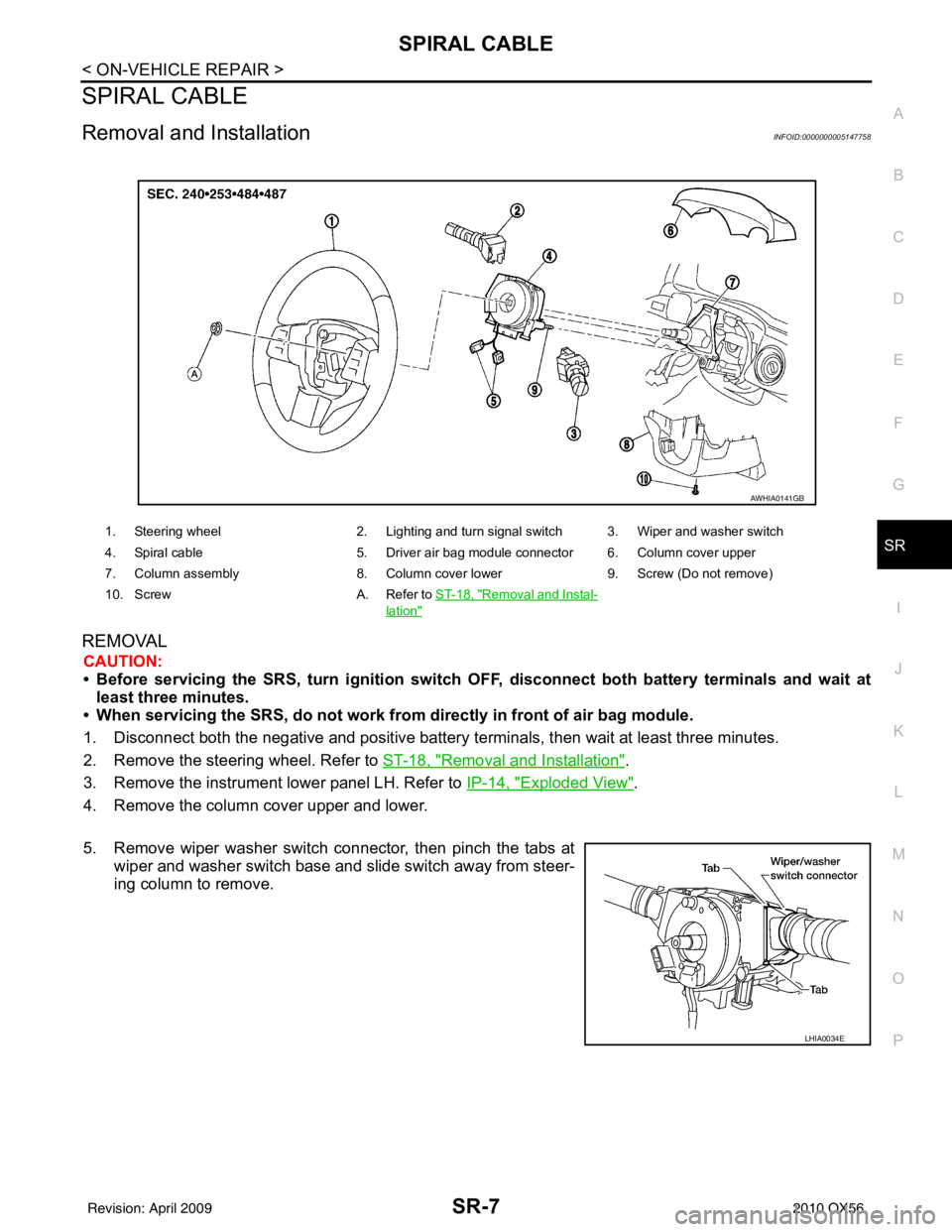
Removal and InstallationINFOID:0000000005147758
REMOVAL
CAUTION:
• Before servicing the SRS, turn ignition switch OFF, disconnect both battery terminals and wait at
least three minutes.
• When servicing the SRS, do not work from directly in front of air bag module.
1. Disconnect both the negative and positive battery te rminals, then wait at least three minutes.
2. Remove the steering wheel. Refer to ST-18, "
Removal and Installation".
3. Remove the instrument lower panel LH. Refer to IP-14, "
Exploded View".
4. Remove the column cover upper and lower.
5. Remove wiper washer switch connector, then pinch the tabs at wiper and washer switch base and slide switch away from steer-
ing column to remove.
1. Steering wheel 2. Lighting and turn signal switch 3. Wiper and washer switch
4. Spiral cable 5. Driver air bag module connector 6. Column cover upper
7. Column assembly 8. Column cover lower9. Screw (Do not remove)
10. Screw A. Refer to ST-18, "
Removal and Instal-
lation"
AWHIA0141GB
LHIA0034E
Revision: April 20092010 QX56
Page 4049 of 4210

WCS-50
< ECU DIAGNOSIS >
BCM (BODY CONTROL MODULE)
BCM (BODY CONTROL MODULE)
Reference ValueINFOID:0000000005382423
VALUES ON THE DIAGNOSIS TOOL
Monitor ItemCondition Value/Status
AIR COND SW A/C switch OFF
OFF
A/C switch ON ON
AUT LIGHT SYS Outside of the room is dark
OFF
Outside of the room is bright ON
AUTO LIGHT SW Lighting switch OFF
OFF
Lighting switch AUTO ON
BACK DOOR SW Back door closed
OFF
Back door opened ON
CARGO LAMP SW Cargo lamp switch OFF
OFF
Cargo lamp switch ON ON
CDL LOCK SW Door lock/unlock switch does not operate
OFF
Press door lock/unlock switch to the LOCK side ON
CDL UNLOCK SW Door lock/unlock switch does not operate
OFF
Press door lock/unlock switch to the UNLOCK side ON
DOOR SW-AS Front door RH closed
OFF
Front door RH opened ON
DOOR SW-DR Front door LH closed
OFF
Front door LH opened ON
DOOR SW-RL Rear door LH closed
OFF
Rear door LH opened ON
DOOR SW-RR Rear door RH closed
OFF
Rear door RH opened ON
ENGINE RUN Engine stopped
OFF
Engine running ON
FR FOG SW Front fog lamp switch OFF
OFF
Front fog lamp switch ON ON
FR WASHER SW Front washer switch OFF
OFF
Front washer switch ON ON
FR WIPER LOW Front wiper switch OFF
OFF
Front wiper switch LO ON
FR WIPER HI Front wiper switch OFF
OFF
Front wiper switch HI ON
FR WIPER INT Front wiper switch OFF
OFF
Front wiper switch INT ON
FR WIPER STOP Any position other than front wiper stop position
OFF
Front wiper stop position ON
HAZARD SW When hazard switch is not pressed
OFF
When hazard switch is pressed ON
Revision: April 20092010 QX56
Page 4050 of 4210

WCS
BCM (BODY CONTROL MODULE)WCS-51
< ECU DIAGNOSIS >
C
DE
F
G H
I
J
K L
M B A
O P
LIGHT SW 1ST Lighting switch OFF OFF
Lighting switch 1st
ON
HEAD LAMP SW1 Headlamp switch OFF
OFF
Headlamp switch 1st ON
HEAD LAMP SW2 Headlamp switch OFF
OFF
Headlamp switch 1st ON
HI BEAM SW High beam switch OFF
OFF
High beam switch HI ON
IGN ON SW Ignition switch OFF or ACC
OFF
Ignition switch ON ON
IGN SW CAN Ignition switch OFF or ACC
OFF
Ignition switch ON ON
INT VOLUME Wiper intermittent dial is in a dial position 1 - 7 1 - 7
I-KEY LOCK LOCK button of Intelligent Key is not pressed
OFF
LOCK button of Intelligent Key is pressed ON
I-KEY UNLOCK UNLOCK button of Intelligent Key is not pressed
OFF
UNLOCK button of Intelligent Key is pressed ON
KEY CYL LK-SW Door key cylinder LOCK position
ON
Door key cylinder other than LOCK position OF
KEY CYL UN-SW Door key cylinder UNLOCK position
ON
Door key cylinder other than UNLOCK position ON
KEY ON SW Mechanical key is removed from key cylinder
OFF
Mechanical key is inserted to key cylinder ON
OIL PRESS SW • Ignition switch OFF or ACC
• Engine running
OFF
Ignition switch ON ON
OPTICAL SENSOR Bright outside of the vehicle
Close to 5V
Dark outside of the vehicle Close to 0V
PASSING SW Other than lighting switch PASS
OFF
Lighting switch PASS ON
PUSH SW Return to ignition switch to LOCK position
OFF
Press ignition switch ON
REAR DEF SW Rear window defogger switch OFF
OFF
Rear window defogger switch ON ON
RR WASHER SW Rear washer switch OFF
OFF
Rear washer switch ON ON
RR WIPER INT Rear wiper switch OFF
OFF
Rear wiper switch INT ON
RR WIPER ON Rear wiper switch OFF
OFF
Rear wiper switch ON ON
RR WIPER STOP Rear wiper stop position
OFF
Other than rear wiper stop position ON
RR WIPER STP2 Rear wiper stop position
OFF
Other than rear wiper stop position ON
Monitor Item
Condition Value/Status
Revision: April 20092010 QX56
Page 4053 of 4210

WCS-54
< ECU DIAGNOSIS >
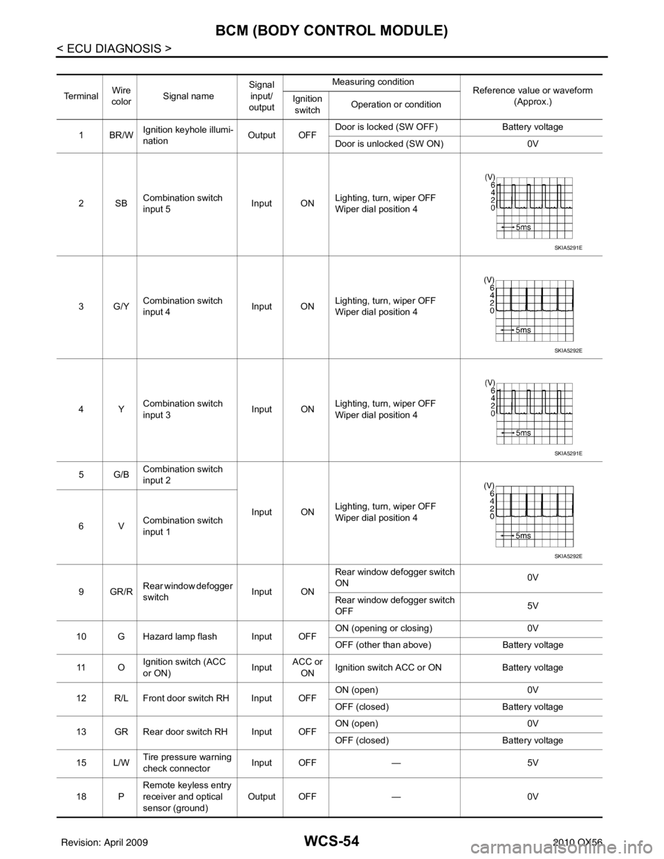
BCM (BODY CONTROL MODULE)
Te r m i n a lWire
color Signal name Signal
input/
output Measuring condition
Reference value or waveform
(Approx.)
Ignition
switch Operation or condition
1BR/W Ignition keyhole illumi-
nation Output OFFDoor is locked (SW OFF)
Battery voltage
Door is unlocked (SW ON) 0V
2SB Combination switch
input 5 Input ON
Lighting, turn, wiper OFF
Wiper dial position 4
3G/Y Combination switch
input 4 Input ONLighting, turn, wiper OFF
Wiper dial position 4
4Y Combination switch
input 3 Input ON
Lighting, turn, wiper OFF
Wiper dial position 4
5G/B Combination switch
input 2
Input ONLighting, turn, wiper OFF
Wiper dial position 4
6V Combination switch
input 1
9GR/R Rear window defogger
switch
Input ONRear window defogger switch
ON
0V
Rear window defogger switch
OFF 5V
10 G Hazard lamp flash Input OFF ON (opening or closing)
0V
OFF (other than above) Battery voltage
11 O Ignition switch (ACC
or ON)
InputACC or
ON Ignition switch ACC or ON
Battery voltage
12 R/L Front door switch RH Input OFF ON (open)
0V
OFF (closed) Battery voltage
13 GR Rear door switch RH Input OFF ON (open)
0V
OFF (closed) Battery voltage
15 L/W Tire pressure warning
check connector
Input OFF
—5V
18 P Remote keyless entry
receiver and optical
sensor (ground)
Output OFF
—0V
SKIA5291E
SKIA5292E
SKIA5291E
SKIA5292E
Revision: April 20092010 QX56
Page 4054 of 4210

WCS
BCM (BODY CONTROL MODULE)WCS-55
< ECU DIAGNOSIS >
C
DE
F
G H
I
J
K L
M B A
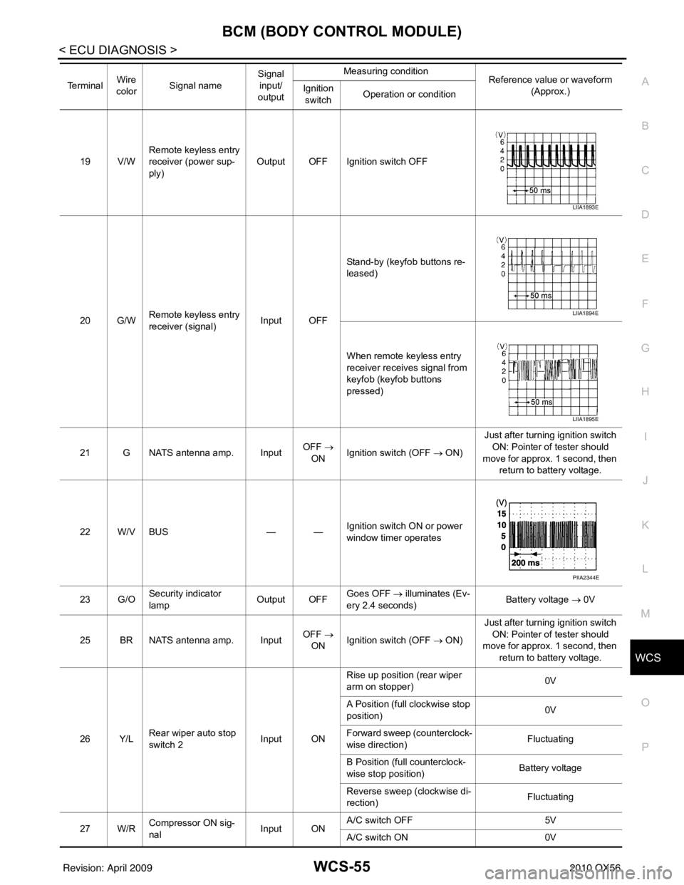
O P19 V/W Remote keyless entry
receiver (power sup-
ply) Output OFF Ignition switch OFF
20 G/W Remote keyless entry
receiver (signal) Input OFFStand-by (keyfob buttons re-
leased)
When remote keyless entry
receiver receives signal from
keyfob (keyfob buttons
pressed)
21 G NATS antenna amp. Input OFF
→
ON Ignition switch (OFF → ON) Just after turning ignition switch
ON: Pointer of tester should
move for approx. 1 second, then return to battery voltage.
22 W/V BUS — —Ignition switch ON or power
window timer operates
23 G/O Security indicator
lamp Output OFF
Goes OFF
→ illuminates (Ev-
ery 2.4 seconds) Battery voltage
→ 0V
25 BR NATS antenna amp. Input OFF
→
ON Ignition switch (OFF → ON) Just after turning ignition switch
ON: Pointer of tester should
move for approx. 1 second, then return to battery voltage.
26 Y/L Rear wiper auto stop
switch 2 Input ONRise up position (rear wiper
arm on stopper)
0V
A Position (full clockwise stop
position) 0V
Forward sweep (counterclock-
wise direction) Fluctuating
B Position (full counterclock-
wise stop position) Battery voltage
Reverse sweep (clockwise di-
rection) Fluctuating
27 W/R Compressor ON sig-
nal Input ONA/C switch OFF
5V
A/C switch ON 0V
Te r m i n a l
Wire
color Signal name Signal
input/
output Measuring condition
Reference value or waveform
(Approx.)
Ignition
switch Operation or condition
LIIA1893E
LIIA1894E
LIIA1895E
PIIA2344E
Revision: April 20092010 QX56
Page 4055 of 4210

WCS-56
< ECU DIAGNOSIS >
BCM (BODY CONTROL MODULE)
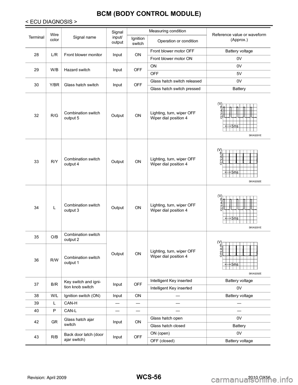
28 L/R Front blower monitor Input ONFront blower motor OFF
Battery voltage
Front blower motor ON 0V
29 W/B Hazard switch Input OFFON
0V
OFF 5V
30 Y/BR Glass hatch switch Input OFF Glass hatch switch released
0V
Glass hatch switch pressed Battery
32 R/G Combination switch
output 5
Output ONLighting, turn, wiper OFF
Wiper dial position 4
33 R/Y Combination switch
output 4 Output ONLighting, turn, wiper OFF
Wiper dial position 4
34 L Combination switch
output 3 Output ON
Lighting, turn, wiper OFF
Wiper dial position 4
35 O/B Combination switch
output 2
Output ONLighting, turn, wiper OFF
Wiper dial position 4
36 R/W Combination switch
output 1
37 B/R Key switch and igni-
tion knob switch Input OFFIntelligent Key inserted
Battery voltage
Intelligent Key inserted 0V
38 W/L Ignition switch (ON) Input ON —Battery voltage
39 L CAN-H — —— —
40 P CAN-L — —— —
42 GR Glass hatch ajar
switch Input ONGlass hatch open
0V
Glass hatch closed Battery
43 R/B Back door latch (door
ajar switch) Input OFFON (open)
0V
OFF (closed) Battery voltage
Te r m i n a l
Wire
color Signal name Signal
input/
output Measuring condition
Reference value or waveform
(Approx.)
Ignition
switch Operation or condition
SKIA5291E
SKIA5292E
SKIA5291E
SKIA5292E
Revision: April 20092010 QX56