2010 INFINITI QX56 4WD
[x] Cancel search: 4WDPage 2270 of 4210

CONSULT-III CHECKING SYSTEMGI-47
< BASIC INSPECTION >
C
DE
F
G H
I
J
K L
M B
GI
N
O P
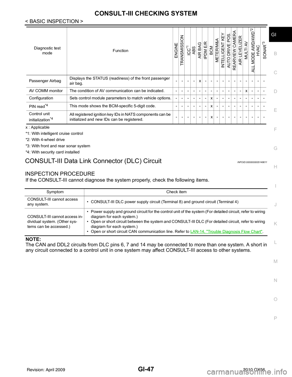
x : Applicable
*1: With intelligent cruise control
*2: With 4-wheel drive
*3: With front and rear sonar system
*4: With security card installed
CONSULT-III Data Link Connector (DLC) CircuitINFOID:0000000005149611
INSPECTION PROCEDURE
If the CONSULT-III cannot diagnose the sys tem properly, check the following items.
NOTE:
The CAN and DDL2 circuits from DLC pins 6, 7 and 14 may be connected to more than one system. A short in
any circuit connected to a control unit in one system may affect CONSULT-III access to other systems.
Passenger AirbagDisplays the STATUS (readiness) of the front passenger
air bag. ----x-----------
AV COMM monitor The condition of AV communication can be indicated. ------------x---
Configuration Sets control module parameters to match vehicle options.------x---------
PIN read
*4This mode shows the BCM-specific 5-digit code. ------x---------
Control unit
initialization
*4All registered ignition key IDs in NATS components can be
initialized and new IDs can be registered. ------x---------
Diagnostic test
mode Function
ENGINE
TRANSMISSION
ICC
*1
ABS
AIR BAG
IPDM E/R BCM
METER/M&A
INTELLIGENT KEY
AUTO DRIVE POS.
REARVIEW CAMERA AIR LEVELIZER MULTI AV
ALL MODE AWD/4WD
*2
HVAC
SONAR
*3
Symptom Check item
CONSULT-III cannot access
any system. • CONSULT-III DLC power supply circuit (Terminal 8) and ground circuit (Terminal 4)
CONSULT-III cannot access in-
dividual system. (Other sys-
tems can be accessed.) • Power supply and ground circuit for the control unit of the system (For detailed circuit, refer to wiring
diagram for each system.)
• Open or short circuit between the system and CONSULT-III DLC (For detailed circuit, refer to wiring
diagram for each system.)
• Open or short circuit CAN communication line. Refer to LAN-14, "
Trouble Diagnosis Flow Chart".
Revision: April 20092010 QX56
Page 2585 of 4210

IP-12
< ON-VEHICLE REPAIR >
INSTRUMENT PANEL ASSEMBLY
Removal and Installation
INFOID:0000000005147362
REMOVAL
CAUTION:
Disconnect both the negative and po sitive battery terminals in advance.
1. Disconnect both negative and positive termi nals, then wait at least 3 minutes.
2. Remove front center console. Refer to IP-20, "
Removal and Installation".
3. Remove steering column assembly. Refer to ST-20, "
Removal and Installation".
4. Remove combination meter. Refer to MWI-100, "
Removal and Installation".
5. Remove instrument panel upper cover and disconnect rear sonar speaker.
6. Remove cluster lid C. Refer to IP-15, "
Removal and Installation".
7. Remove display assembly. Refer to AV-169, "
Removal and Installation".
8. Remove instrument lower/upper panel RH and glove box. Refer to IP-17, "
Removal and Installation" and
IP-18, "
Removal and Installation".
9. Release the clips, disconnect the optical sensor harness and remove defroster grille.
10. Release the clips, disconnect the connecto rs and remove RH, LH, and center speakers.
11. Remove RH/LH front pillar finishers. Refer to INT-14, "
Removal and Installation".
12. Remove the passenger air bag module nuts and disconnect the connectors. Refer to SR-10, "
Removal
and Installation".
13. Disconnect remaining optional equipment connectors (if equipped).
14. Remove instrument panel and pad assembly screws.
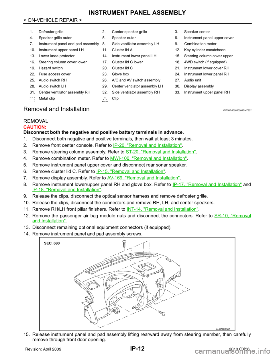
15. Release instrument panel and pad assembly lifting rearward away from steering member, then carefully remove through front door opening.
1. Defroster grille 2. Center speaker grille3. Speaker center
4. Speaker grille outer 5. Speaker outer6. Instrument panel upper cover
7. Instrument panel and pad assembly 8. Side ventilator assembly LH 9. Combination meter
10. Instrument upper panel LH 11. Cluster lid A 12. Key cylinder escutcheon
13. Lower knee protector 14. Instrument lower panel LH 15. Steering column cover upper
16. Steering column cover lower 17. Cluster lid C lower 18. 4WD switch (if equipped)
19. Hazard switch 20. Cluster lid C21. Instrument lower cover RH
22. Fuse access cover 23. Glove box 24. Instrument lower panel RH
25. Audio switch RH 26. A/C and AV switch assembly 27. Audio unit
28. Audio switch LH 29. Center ventilator assembly LH 30. Display assembly
31. Center ventilator assembly RH 32. Side ventilator assembly RH 33. Instrument upper panel RH Metal clip Clip
ALJIA0083ZZ
Revision: April 20092010 QX56
Page 2588 of 4210

CLUSTER LID CIP-15
< ON-VEHICLE REPAIR >
C
DE
F
G H
I
K L
M A
B
IP
N
O P
CLUSTER LID C
Exploded ViewINFOID:0000000005147365
Removal and InstallationINFOID:0000000005147366
REMOVAL
1. Disconnect battery negative terminal.
2. Release the clips and remove cluster lid C lower.
3. Remove the upper and lower cluster lid C screws.
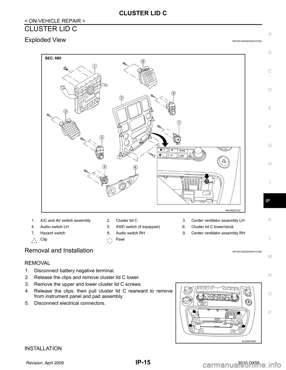
4. Release the clips, then pull cluster lid C rearward to remove from instrument panel and pad assembly.
5. Disconnect electrical connectors.
INSTALLATION
1. A/C and AV switch assembly 2. Cluster lid C 3. Center ventilator assembly LH
4. Audio switch LH 5. 4WD switch (if equipped) 6. Cluster lid C lower/clock
7. Hazard switch 8. Audio switch RH9. Center ventilator assembly RH
Clip Pawl
AWJIA0237ZZ
ALJIA0078ZZ
Revision: April 20092010 QX56
Page 2600 of 4210

LAN-2
MAIN LINE BETWEEN TCM AND LASER
CIRCUIT .............................................................
63
Diagnosis Procedure ........................................... ...63
MAIN LINE BETWEEN LASER AND ICC CIR-
CUIT ...................................................................
64
Diagnosis Procedure ........................................... ...64
MAIN LINE BETWEEN ICC AND ADP CIR-
CUIT ...................................................................
65
Diagnosis Procedure ........................................... ...65
MAIN LINE BETWEEN ADP AND AV CIR-
CUIT ...................................................................
66
Diagnosis Procedure ........................................... ...66
MAIN LINE BETWEEN AV AND DLC CIR-
CUIT ...................................................................
67
Diagnosis Procedure ........................................... ...67
MAIN LINE BETWEEN DLC AND M&A CIR-
CUIT ...................................................................
68
Diagnosis Procedure ........................................... ...68
MAIN LINE BETWEEN M&A AND ABS CIR-
CUIT ...................................................................
69
Diagnosis Procedure ........................................... ...69
MAIN LINE BETWEEN M&A AND 4WD CIR-
CUIT ...................................................................
70
Diagnosis Procedure ........................................... ...70
MAIN LINE BETWEEN 4WD AND ABS CIR-
CUIT ...................................................................
71
Diagnosis Procedure ........................................... ...71
ECM BRANCH LINE CIRCUIT ..........................72
Diagnosis Procedure ........................................... ...72
TCM BRANCH LINE CIRCUIT ..........................73
Diagnosis Procedure ........................................... ...73
LASER BRANCH LINE CIRCUIT ......................74
Diagnosis Procedure ............................................ ...74
ICC BRANCH LINE CIRCUIT ............................75
Diagnosis Procedure ............................................ ...75
ADP BRANCH LINE CIRCUIT ..........................76
Diagnosis Procedure ............................................ ...76
AV BRANCH LINE CIRCUIT .............................77
Diagnosis Procedure ............................................ ...77
BCM BRANCH LINE CIRCUIT ..........................78
Diagnosis Procedure ............................................ ...78
DLC BRANCH LINE CIRCUIT ..........................79
Diagnosis Procedure ............................................ ...79
HVAC BRANCH LINE CIRCUIT ........................80
Diagnosis Procedure ............................................ ...80
I-KEY BRANCH LINE CIRCUIT ........................81
Diagnosis Procedure ............................................ ...81
M&A BRANCH LINE CIRCUIT ..........................82
Diagnosis Procedure ............................................ ...82
STRG BRANCH LINE CIRCUIT ........................83
Diagnosis Procedure ............................................ ...83
4WD BRANCH LINE CIRCUIT ..........................84
Diagnosis Procedure ............................................ ...84
ABS BRANCH LINE CIRCUIT ..........................85
Diagnosis Procedure ............................................ ...85
IPDM-E BRANCH LINE CIRCUIT .....................86
Diagnosis Procedure ............................................ ...86
CAN COMMUNICATION CIRCUIT ...................87
Diagnosis Procedure ............................................ ...87
Revision: April 20092010 QX56
Page 2634 of 4210
![INFINITI QX56 2010 Factory Service Manual LAN-36
< HOW TO USE THIS MANUAL >[CAN]
HOW TO USE THIS SECTION
HOW TO USE THIS MANUAL
HOW TO USE THIS SECTION
CautionINFOID:0000000005146452
• This section describes information peculiar to a v
ehic INFINITI QX56 2010 Factory Service Manual LAN-36
< HOW TO USE THIS MANUAL >[CAN]
HOW TO USE THIS SECTION
HOW TO USE THIS MANUAL
HOW TO USE THIS SECTION
CautionINFOID:0000000005146452
• This section describes information peculiar to a v
ehic](/manual-img/42/57032/w960_57032-2633.png)
LAN-36
< HOW TO USE THIS MANUAL >[CAN]
HOW TO USE THIS SECTION
HOW TO USE THIS MANUAL
HOW TO USE THIS SECTION
CautionINFOID:0000000005146452
• This section describes information peculiar to a v
ehicle, sheets for trouble diagnosis, and inspection proce-
dures.
• For trouble diagnosis procedure, refer to LAN-14, "
Trouble Diagnosis Procedure".
Abbreviation ListINFOID:0000000005146453
Abbreviations in CAN communication signal chart, and the diagnosis sheet are as per the following list.
AbbreviationUnit nameSELECT SYSTEM
(CONSULT-III) CAN DIAG SUPPORT MNTR
(CONSULT-III)
4WD Transfer control unit ALL MODE AWD/4WDAWD/4WD
A-BAG Air bag diagnosis sensor unit AIR BAG—
ABS ABS actuator and electric unit (control unit) ABSVDC/TCS/ABS
ADP Driver seat control unit AUTO DRIVE POS.—
AV AV c o n t r o l u n i t M U LT I AVD I S P L AY
BCM BCM BCMBCM/SEC
DLC Data link connector ——
ECM ECM ENGINEECM
HVAC A/C auto amp. HVAC—
ICC ICC unit ICCICC
ICC/e4WD
I-KEY Intelligent Key unit INTELLIGENT KEYI-KEY
IPDM-E IPDM E/R IPDM E/RIPDM E/R
LASER ICC sensor —ICC SENSOR
M&A Combination meter METER/M&AMETER/M&A
STRG Steering angle sensor —STRG
TCM TCMTRANSMISSION TCM
Revision: April 20092010 QX56
Page 2642 of 4210
![INFINITI QX56 2010 Factory Service Manual LAN-44
< FUNCTION DIAGNOSIS >[CAN]
CAN COMMUNICATION SYSTEM
FUNCTION DIAGNOSIS
CAN COMMUNICATION SYSTEM
CAN System Specification ChartINFOID:0000000005146462
Determine CAN system type from the followi INFINITI QX56 2010 Factory Service Manual LAN-44
< FUNCTION DIAGNOSIS >[CAN]
CAN COMMUNICATION SYSTEM
FUNCTION DIAGNOSIS
CAN COMMUNICATION SYSTEM
CAN System Specification ChartINFOID:0000000005146462
Determine CAN system type from the followi](/manual-img/42/57032/w960_57032-2641.png)
LAN-44
< FUNCTION DIAGNOSIS >[CAN]
CAN COMMUNICATION SYSTEM
FUNCTION DIAGNOSIS
CAN COMMUNICATION SYSTEM
CAN System Specification ChartINFOID:0000000005146462
Determine CAN system type from the following specificat
ion chart. Then choose the correct diagnosis sheet.
NOTE:
Refer to LAN-14, "
Trouble Diagnosis Procedure" for how to use CAN system specification chart.
×: Applicable
VEHICLE EQUIPMENT IDENTIFICATION INFORMATION
NOTE:
Check CAN system type from the vehicle shape and equipment.
CAN Communication Signal ChartINFOID:0000000005146463
Refer to LAN-13, "How to Use CAN Communication Signal Chart" for how to use CAN communication signal
chart.
NOTE:
Refer to LAN-36, "
Abbreviation List" for the abbreviations of the connecting units.
T: Transmit R: Receive
Body type Wagon
Axle 2WD4WD
Engine VK56DE
Transmission A/T
Brake control VDC
ICC system ××
CAN system type 12 34
Diagnosis sheet LAN-40
LAN-41LAN-42LAN-43
AWMIA0012GB
Signal name/Connecting unitECM
TCM
LASER ICC
ADP
AV
BCM
HVAC I-KEY M&A
STRG 4WDABS
IPDM-E
Accelerator pedal position signal T RR R R
A/C compressor request signal T R
ASCD CRUISE lamp signal T R
ASCD OD cancel request signal T R
ASCD operation signal T R
ASCD SET lamp signal T R
Battery voltage signal T R
Closed throttle position signal T RR
Cooling fan speed request signal T R
Engine coolant temperature signal T RR
Revision: April 20092010 QX56
Page 2643 of 4210
![INFINITI QX56 2010 Factory Service Manual LAN
CAN COMMUNICATION SYSTEMLAN-45
< FUNCTION DIAGNOSIS > [CAN]
C
D
E
F
G H
I
J
K L
B A
O P
N
Engine speed signal
T RRR R R R R R
Engine status signal TR
Fuel consumption monitor signal TR
RT
ICC stee INFINITI QX56 2010 Factory Service Manual LAN
CAN COMMUNICATION SYSTEMLAN-45
< FUNCTION DIAGNOSIS > [CAN]
C
D
E
F
G H
I
J
K L
B A
O P
N
Engine speed signal
T RRR R R R R R
Engine status signal TR
Fuel consumption monitor signal TR
RT
ICC stee](/manual-img/42/57032/w960_57032-2642.png)
LAN
CAN COMMUNICATION SYSTEMLAN-45
< FUNCTION DIAGNOSIS > [CAN]
C
D
E
F
G H
I
J
K L
B A
O P
N
Engine speed signal
T RRR R R R R R
Engine status signal TR
Fuel consumption monitor signal TR
RT
ICC steering switch signal TR
Malfunction indicator lamp signal T R
Wide open throttle position signal T R
A/T CHECK indicato r lamp signal T R
A/T fluid temperature sensor signal T R
A/T position indicator lamp signal TR RR
A/T self-diagnosis signal R T
Current gear position signal TR R
Input speed signal R TR
Output shaft revolution signal R TR R
P range signal TR R RR
ICC sensor signal T R
Buzzer output signal TR
TR
ICC OD cancel request signal R RT
ICC operation signal R RT
ICC system display signal TR
System setting signal TRT
RTR
A/C switch/indicator signal TR
RT
A/C switch signal RT R
Blower fan motor switch signal RT
Day time running light request signal TR R
Door lock/unlock status signal TR
Door switch signal R R TR R R
Front fog light request signal TR
Front wiper request signal RT R
High beam request signal TR R
Horn chirp signal TR
Ignition switch signal RTR R
Key fob door unlock signal RT
Key fob ID signal RT
Key switch signal RT
Low beam request signal TR
Position light request signal TR R
Rear window defogger switch signal T RR
Sleep wake up signal RT R R
Theft warning horn request signal TR
Signal name/Connecting unit
ECM
TCM
LASER ICC
ADP AV
BCM
HVAC I-KEY M&A
STRG 4WD
ABS
IPDM-E
Revision: April 20092010 QX56
Page 2644 of 4210
![INFINITI QX56 2010 Factory Service Manual LAN-46
< FUNCTION DIAGNOSIS >[CAN]
CAN COMMUNICATION SYSTEM
NOTE:
CAN data of the air bag diagnosis sensor unit is not us
ed by usual service work, thus it is omitted.
Tire pressure data signal R T
T INFINITI QX56 2010 Factory Service Manual LAN-46
< FUNCTION DIAGNOSIS >[CAN]
CAN COMMUNICATION SYSTEM
NOTE:
CAN data of the air bag diagnosis sensor unit is not us
ed by usual service work, thus it is omitted.
Tire pressure data signal R T
T](/manual-img/42/57032/w960_57032-2643.png)
LAN-46
< FUNCTION DIAGNOSIS >[CAN]
CAN COMMUNICATION SYSTEM
NOTE:
CAN data of the air bag diagnosis sensor unit is not us
ed by usual service work, thus it is omitted.
Tire pressure data signal R T
Tire pressure signal R TR
Turn indicator signal TR
Buzzer output signal TR
Door lock/unlock request signal RT
Hazard request signal RT
Hazard warning lamp request signal RT
Ignition knob switch signal RT
KEY warning signal TR
LOCK warning signal TR
Panic alarm request signal RT
Power window open request signal RT
1st position switch signal R T
4th position switch signal R T
Distance to empty signal RT
Fuel level low warning signal RT
Fuel level sensor signal R T
Parking brake switch signal RT
Seat belt buckle switch signal RT
Stop lamp switch signal R T
Tow mode switch signal R T
Vehicle speed signal RRR RRR R T
RRRT
Steering angle sensor signal TR
ABS malfunction signal RT
ABS warning lamp signal RT
Brake pressure sensor signal RT
Brake warning lamp signal RT
SLIP indicator lamp signal RT
TCS malfunction signal RT
VDC malfunction signal RT
VDC OFF indicator lamp signal RRT
VDC operation signal RT
Front wiper stop position signal RT
High beam status signal R T
Hood switch signal RT
Low beam status signal R T
Rear window defogger control signal R RT
Signal name/Connecting unit
ECM
TCM
LASER ICC
ADP
AV
BCM
HVAC I-KEY M&A
STRG 4WDABS
IPDM-E
Revision: April 20092010 QX56