Page 2223 of 4210
FSU-24
< SERVICE DATA AND SPECIFICATIONS (SDS)
SERVICE DATA AND SPECIFICATIONS (SDS)
*2: Target value 37° 31 ′ (37.52 °)
*3: Target value 33 ° 59 ′ (33.98 °)
*4: Target value 37 ° 44 ′ (37.73 °)
*5: Target value 33 ° 29 ′ (33.48 °)
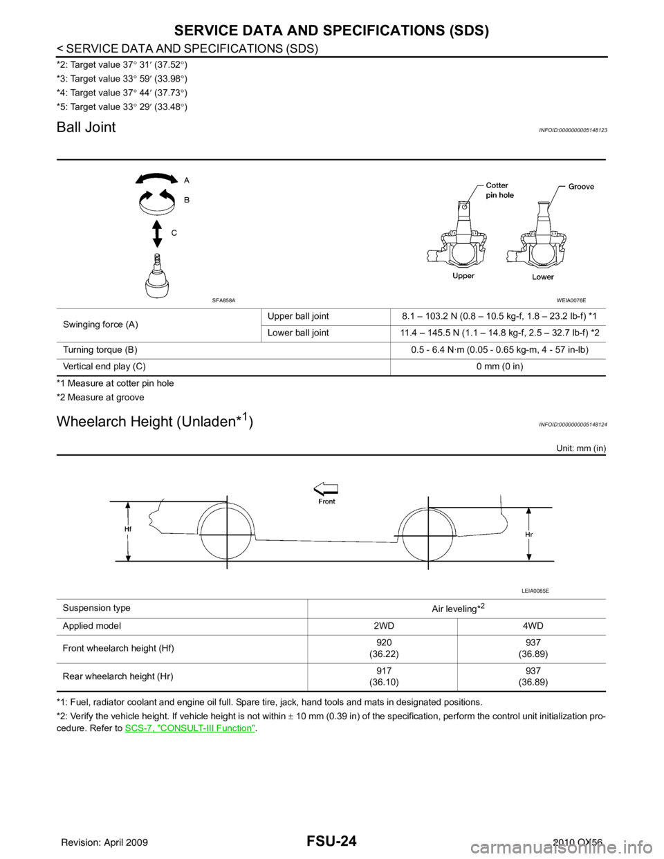
Ball JointINFOID:0000000005148123
*1 Measure at cotter pin hole
*2 Measure at groove
Wheelarch Height (Unladen*1)INFOID:0000000005148124
Unit: mm (in)
*1: Fuel, radiator coolant and engine oil full. Spare tire, jack, hand tools and mats in designated positions.
*2: Verify the vehicle height. If vehicle height is not within ± 10 mm (0.39 in) of the specification, perform the control unit initialization pro-
cedure. Refer to SCS-7, "
CONSULT-III Function".
Swinging force (A)
Upper ball joint
8.1 – 103.2 N (0.8 – 10.5 kg-f, 1.8 – 23.2 lb-f) *1
Lower ball joint 11.4 – 145.5 N (1.1 – 14.8 kg-f, 2.5 – 32.7 lb-f) *2
Turning torque (B) 0.5 - 6.4 N·m (0.05 - 0.65 kg-m, 4 - 57 in-lb)
Vertical end play (C) 0 mm (0 in)
SFA858AWEIA0076E
Suspension type
Air leveling*2
Applied model2WD4WD
Front wheelarch height (Hf) 920
(36.22) 937
(36.89)
Rear wheelarch height (Hr) 917
(36.10) 937
(36.89)
LEIA0085E
Revision: April 20092010 QX56
Page 2236 of 4210
ABBREVIATIONSGI-13
< HOW TO USE THIS MANUAL >
C
DE
F
G H
I
J
K L
M B
GI
N
O PABBREVIATIONS
Abbreviation ListINFOID:0000000005149579
The following ABBREVIATIONS are used:
ABBREVIATION DESCRIPTION
A/C Air Conditioner
A/T Automatic Transaxle/Transmission
ATF Automatic Transmission Fluid
D
1Drive range 1st gear
D
2Drive range 2nd gear
D
3Drive range 3rd gear
D
4Drive range 4th gear
D5 Drive range 5th gear
FR, RR Front, Rear LH, RH Left-Hand, Right-Hand M/T Manual Transaxle/Transmission
OD Overdrive
P/S Power Steering
SAE Society of Automotive Engineers, Inc.
SDS Service Data and Specifications
SST Special Service Tools
2WD 2-Wheel Drive
4WD 4-Wheel Drive
2
22nd range 2nd gear
2
12nd range 1st gear
1
21st range 2nd gear
1
11st range 1st gear
Revision: April 20092010 QX56
Page 2243 of 4210
GI-20
< FEATURES OF NEW MODEL >
IDENTIFICATION INFORMATION
FEATURES OF NEW MODEL
IDENTIFICATION INFORMATION
Model VariationINFOID:0000000005149583
Prefix and suffix designations:
Drive Type Body Engine Transmission Destination GradeModel
2WD Wagon VK56DE RE5R05A (5A/T) U.S.A. QX56 JPKALVN-EUA
4WD Wagon VK56DE RE5R05A (5A/T) U.S.A.
QX56JPKWLVN-EUA
Canada JPKWLVN-ENA
Position Character Qualifier Definition
1 J Body type J: Wagon
2 PK Engine PK: VK56DE
3
4AA xle A: 2WD
W: 4WD
5LD riv e L : L H
6 V Grade V: QX56
7 N Transmission N: RE5R05A (5A/T)
8 I82 Model I82: 2010 QX56
9
10 11 E I n t a k e E : E G I
12 U Zone N: Canada
U: Federal
13 A Equipment A: Standard
14
XXXXX Option Codes Option Codes
15
16
17
18
Revision: April 20092010 QX56
Page 2244 of 4210
IDENTIFICATION INFORMATIONGI-21
< FEATURES OF NEW MODEL >
C
DE
F
G H
I
J
K L
M B
GI
N
O P
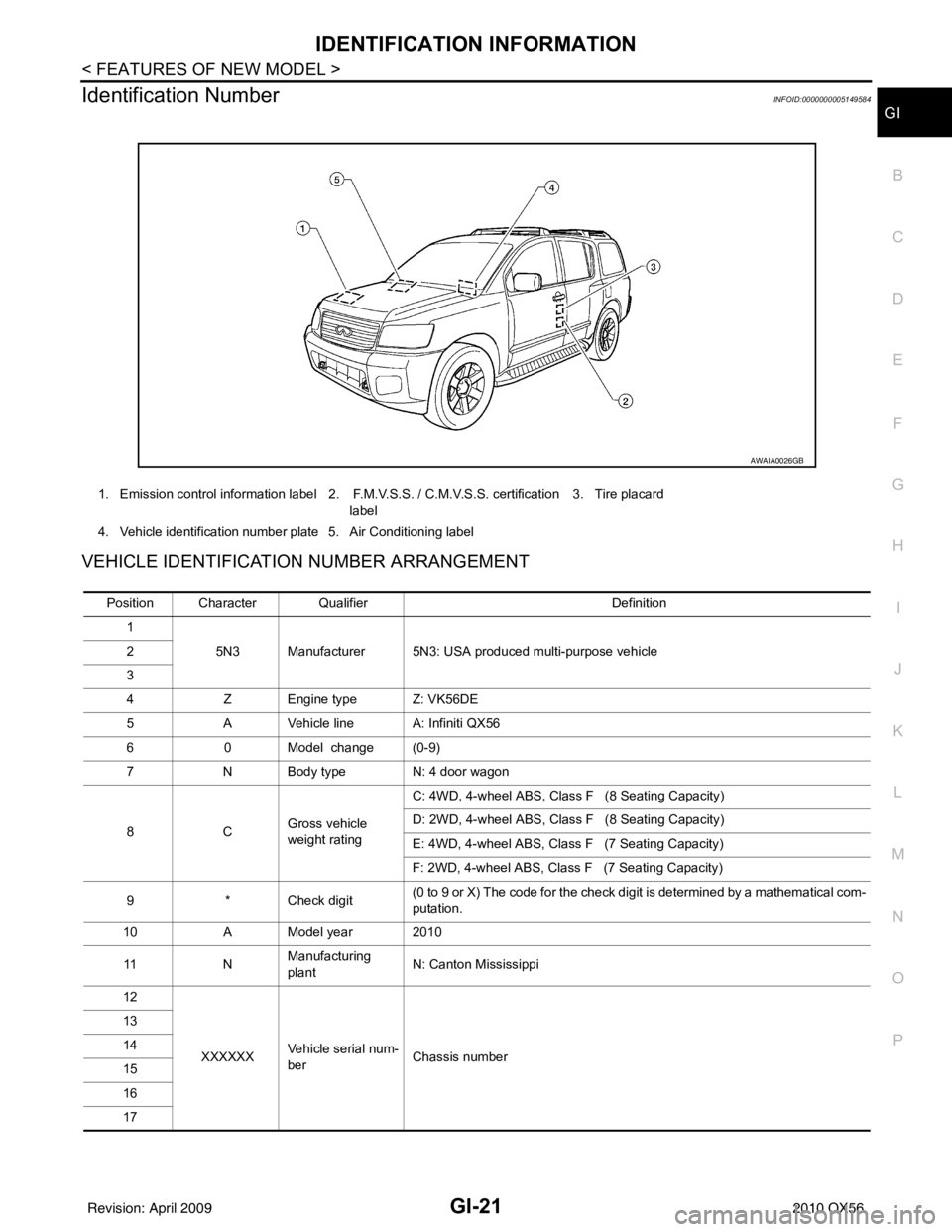
Identification NumberINFOID:0000000005149584
VEHICLE IDENTIFICATION NUMBER ARRANGEMENT
1. Emission control information label 2. F.M.V.S.S. / C.M.V.S.S. certification label3. Tire placard
4. Vehicle identification number plate 5. Air Conditioning label
AWAIA0026GB
Position Character Qualifier Definition
1 5N3 Manufacturer 5N3: USA produced multi-purpose vehicle
2
3
4 Z Engine type Z: VK56DE
5 A Vehicle line A: Infiniti QX56
6 0 Model change (0-9)
7 N Body type N: 4 door wagon
8C Gross vehicle
weight ratingC: 4WD, 4-wheel ABS, Class F (8 Seating Capacity)
D: 2WD, 4-wheel ABS, Class F (8 Seating Capacity)
E: 4WD, 4-wheel ABS, Class F (7 Seating Capacity)
F: 2WD, 4-wheel ABS, Class F (7 Seating Capacity)
9 * Check digit (0 to 9 or X) The code for the check digit is determined by a mathematical com-
putation.
10 A Model year 2010
11 NManufacturing
plant
N: Canton Mississippi
12
XXXXXX Vehicle serial num-
ber Chassis number
13
14
15
16
17
Revision: April 20092010 QX56
Page 2246 of 4210
IDENTIFICATION INFORMATIONGI-23
< FEATURES OF NEW MODEL >
C
DE
F
G H
I
J
K L
M B
GI
N
O P
DimensionsINFOID:0000000005149586
Unit: mm (in)
Wheels & TiresINFOID:0000000005149587
* With Steel Wheel Drive type
2WD4WD
Overall length 5254 (206.9)5254 (206.9)
Overall width 2021 (79.6)2021 (79.6)
Overall height (with roof rack) 1948 (76.7)1968 (77.5)
Front tread width 1729 (68.1)1729 (68.1)
Rear tread width 1729 (68.1)1729 (68.1)
Wheelbase 3130 (123.2)3130 (123.2)
Minimum Running Ground Clearance (at front suspension) 211.2 (8.3)232 (9.1)
Drive Type Grade Road wheelTireSpare tire size *
All QX56 20x8JJ Chromium Aluminum Alloy
P275/60R20P275/60R20
20X8J Steel P275/60R20P275/60R20
Revision: April 20092010 QX56
Page 2255 of 4210
GI-32
< PRECAUTION >
TOW TRUCK TOWING
TOW TRUCK TOWING
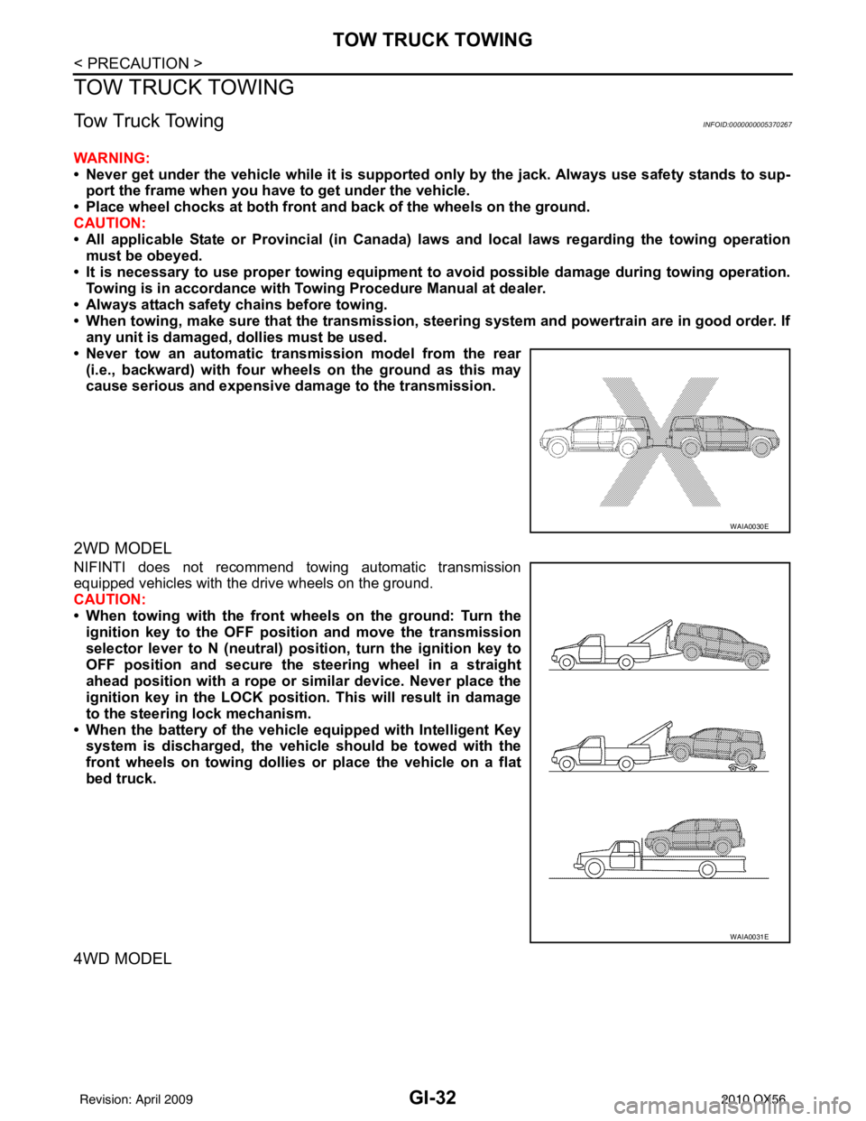
Tow Truck TowingINFOID:0000000005370267
WARNING:
• Never get under the vehicle while it is supported only by the jack. Always use safety stands to sup-
port the frame when you have to get under the vehicle.
• Place wheel chocks at both front an d back of the wheels on the ground.
CAUTION:
• All applicable State or Provincial (in Canada) laws and local laws regarding the towing operation
must be obeyed.
• It is necessary to use proper towing equipment to avoid possible damage during towing operation.
Towing is in accordance with Towing Procedure Manual at dealer.
• Always attach safety chains before towing.
• When towing, make sure that the transmission, steering system and powertrain are in good order. If any unit is damaged, dollies must be used.
• Never tow an automatic transmission model from the rear (i.e., backward) with four wh eels on the ground as this may
cause serious and expensive dama ge to the transmission.
2WD MODEL
NIFINTI does not recommend towing automatic transmission
equipped vehicles with the drive wheels on the ground.
CAUTION:
• When towing with the front wheels on the ground: Turn the
ignition key to the OFF posit ion and move the transmission
selector lever to N (neutral) pos ition, turn the ignition key to
OFF position and secure the steering wheel in a straight
ahead position with a rope or similar device. Never place the
ignition key in the LOCK position. This will result in damage
to the steering lock mechanism.
• When the battery of the vehicle equipped with Intelligent Key system is discharged, the vehicle should be towed with the
front wheels on towing dollies or place the vehicle on a flat
bed truck.
4WD MODEL
WAIA0030E
WAIA0031E
Revision: April 20092010 QX56
Page 2256 of 4210
TOW TRUCK TOWINGGI-33
< PRECAUTION >
C
DE
F
G H
I
J
K L
M B
GI
N
O P
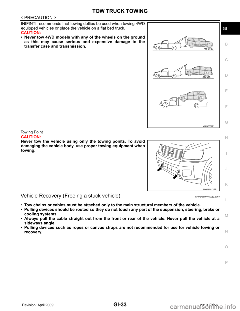
INIFINTI recommends that towing dollies be used when towing 4WD
equipped vehicles or place the vehicle on a flat bed truck.
CAUTION:
• Never tow 4WD models with any of the wheels on the ground as this may cause serious and expensive damage to the
transfer case and transmission.
Towing Point
CAUTION:
Never tow the vehicle using only the towing points. To avoid
damaging the vehicle body, use proper towing equipment when
towing.
Vehicle Recovery (Freeing a stuck vehicle)INFOID:0000000005370268
•Tow chains or cables must be attached only to the main structural members of the vehicle.
• Pulling devices should be routed so they do not touch any part of the suspension, steering, brake or
cooling systems
• Always pull the cable straight out from the front or rear of the vehicle. Never pull the vehicle at a
sideways angle.
• Pulling devices such as ropes or canvas straps are not recommended for use for vehicle towing or
recovery.
WAIA0032E
AWAIA0027GB
Revision: April 20092010 QX56
Page 2269 of 4210
GI-46
< BASIC INSPECTION >
CONSULT-III CHECKING SYSTEM
CONSULT-III CHECKING SYSTEM
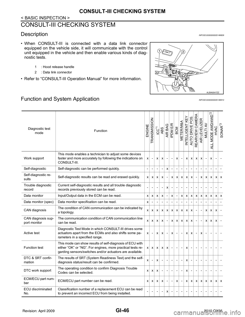
DescriptionINFOID:0000000005149609
• When CONSULT-III is connected with a data link connectorequipped on the vehicle side, it will communicate with the control
unit equipped in the vehicle and then enable various kinds of diag-
nostic tests.
• Refer to “CONSULT-III Operation Manual” for more information.
Function and System ApplicationINFOID:0000000005149610
1 : Hood release handle
2 : Data link connector
ALBIA0047ZZ
Diagnostic test mode Function
ENGINE
TRANSMISSION
ICC
*1
ABS
AIR BAG
IPDM E/R
BCM
METER/M&A
INTELLIGENT KEY
AUTO DRIVE POS.
REARVIEW CAMERA
AIR LEVELIZER MULTI AV
ALL MODE AWD/4WD
*2
HVAC
SONAR
*3
Work support This mode enables a technician to adjust some devices
faster and more accurately by following the indications on
CONSULT-III. x- x x- - x- xxxx- x - -
Self-diagnostic Self-diagnostic can be performed quickly. ----x-----------
Self-diagnostic re-
sults Self-diagnostic results can be read and erased quickly. x x x x - x x x x x - x x x x x
Trouble diagnostic
record Current self-diagnostic results and all trouble diagnostic
records previously stored can be read.
--- - x--- - -------
Data monitor Input/Output data in the ECM can be read. xxx x- x- xxxxxxx xx
Data monitor (spec) Data monitor specification can be read. x---------------
CAN diagnosis The condition of CAN communication can be indicated by
a topology.
xxx xxxxxxx- - xx x-
CAN diagnosis sup-
port monitor The communication condition of CAN communication line
can be read.
xxx x- xxxxx- - xx x-
Active test Diagnostic Test Mode in wh
ich CONSULT-III drives some
actuators apart from the ECMs and also shifts some pa-
rameters in a specified range. x-xx-x--xx-x- - --
Function test This mode can show results of self-diagnosis of ECU with
either “OK” or “NG”. For engines, more practical tests re-
garding sensors/switches and/or actuators are available.
xxxxx---x-------
DTC & SRT confir-
mation The results of SRT (System Readiness Test) and the self-
diagnosis status/result can be confirmed.
x-x-----x-------
DTC work support The operating condition to confirm Diagnosis Trouble
Codes can be selected. xxx-----x-------
ECM/ECU part num-
ber ECM/ECU part number can be read.
xxx x- - x- xxxxxx xx
ECU discriminated
No. Classification number of a replacement ECU can be read
to prevent an incorrect ECU from being installed.
----x-----------
Revision: April 20092010 QX56