2010 INFINITI QX56 brake sensor
[x] Cancel search: brake sensorPage 3715 of 4210
TM-20
< FUNCTION DIAGNOSIS >
A/T CONTROL SYSTEM
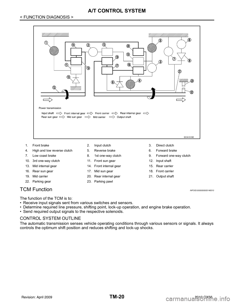
TCM Function
INFOID:0000000005148510
The function of the TCM is to:
• Receive input signals sent from various switches and sensors.
• Determine required line pressure, shifting poi nt, lock-up operation, and engine brake operation.
• Send required output signals to the respective solenoids.
CONTROL SYSTEM OUTLINE
The automatic transmission senses vehicle operating conditions through vari ous sensors or signals. It always
controls the optimum shift position and reduces shifting and lock-up shocks.
1. Front brake 2. Input clutch3. Direct clutch
4. High and low reverse clutch 5. Reverse brake 6. Forward brake
7. Low coast brake 8. 1st one-way clutch 9. Forward one-way clutch
10. 3rd one-way clutch 11. Front sun gear12. Input shaft
13. Mid internal gear 14. Front internal gear15. Rear carrier
16. Rear sun gear 17. Mid sun gear18. Front carrier
19. Mid carrier 20. Rear internal gear21. Output shaft
22. Parking gear 23. Parking pawl
SCIA1519E
Revision: April 20092010 QX56
Page 3716 of 4210
A/T CONTROL SYSTEMTM-21
< FUNCTION DIAGNOSIS >
CEF
G H
I
J
K L
M A
B
TM
N
O P
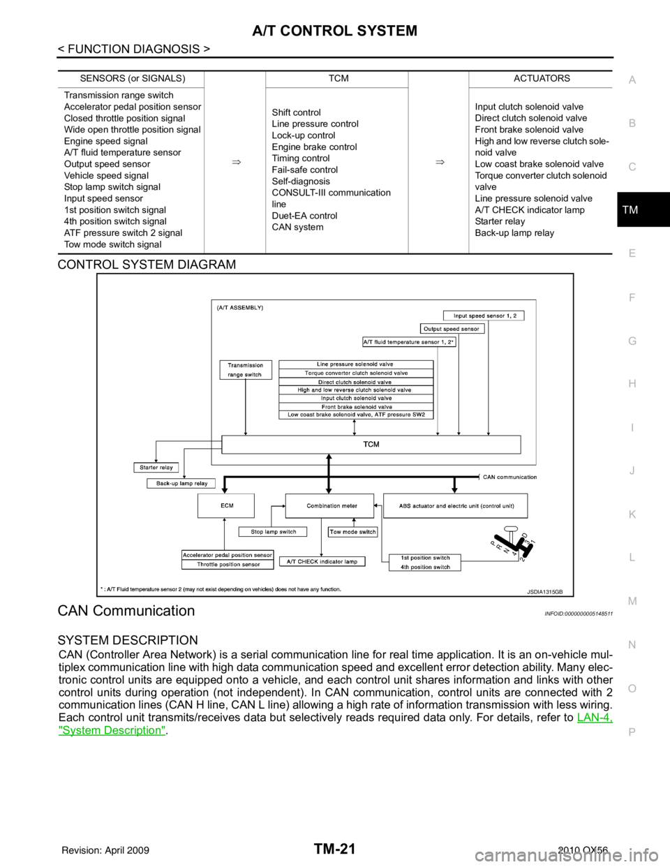
CONTROL SYSTEM DIAGRAM
CAN CommunicationINFOID:0000000005148511
SYSTEM DESCRIPTION
CAN (Controller Area Network) is a serial communication line for real time application. It is an on-vehicle mul-
tiplex communication line with high data communication speed and excellent error detection ability. Many elec-
tronic control units are equipped onto a vehicle, and each control unit shares information and links with other
control units during operation (not independent). In CAN communication, control units are connected with 2
communication lines (CAN H line, CAN L line) allowing a high rate of information transmission with less wiring.
Each control unit transmits/receives data but selectively reads required data only. For details, refer to LAN-4,
"System Description".
SENSORS (or SIGNALS)
⇒TCM
⇒ACTUATORS
Transmission range switch
Accelerator pedal position sensor
Closed throttle position signal
Wide open throttle position signal
Engine speed signal
A/T fluid temperature sensor
Output speed sensor
Vehicle speed signal
Stop lamp switch signal
Input speed sensor
1st position switch signal
4th position switch signal
ATF pressure switch 2 signal
Tow mode switch signal Shift control
Line pressure control
Lock-up control
Engine brake control
Timing control
Fail-safe control
Self-diagnosis
CONSULT-III co
mmunication
line
Duet-EA control
CAN system Input clutch solenoid valve
Direct clutch solenoid valve
Front brake solenoid valve
High and low reverse clutch sole-
noid valve
Low coast brake solenoid valve
Torque converter clutch solenoid
valve
Line pressure solenoid valve
A/T CHECK indicator lamp
Starter relay
Back-up lamp relay
JSDIA1315GB
Revision: April 20092010 QX56
Page 3717 of 4210

TM-22
< FUNCTION DIAGNOSIS >
A/T CONTROL SYSTEM
Input/Output Signal of TCM
INFOID:0000000005148512
*1: Spare for output speed sensor
*2: Spare for accelerator pedal position signal
*3: If these input and output signals are different, the TCM triggers the fail-safe function.
*4: CAN comm unications
*5: Used as a condition for starting self-diagnostics; if self-diagnostics are not started, it is judged that there is some kin d of error.
*6: A/T fluid temperature sensor 2 does not have any function.
Line Pressure ControlINFOID:0000000005148513
• When an input torque signal equivalent to the engine drive force is sent from the ECM to the TCM, the TCM
controls the line pressure solenoid.
Control item Line
pres- sure
control Vehicle
speed
control S h i f t
control Lock-up
control Engine
brake
control Fail-safe
function (*3) Self-diag-
nostics
function
Input Accelerator pedal position signal
(*4)XXXXX X X
Output speed sensor X X X X X X
Vehicle speed signal
(*1) (*4)XXXX X
Closed throttle position signal
(*4)(*2) X (*2) X X (*2) X(*5) X
Wide open throttle position signal
(*4)(*2) X (*2) X (*2) X(*5) X
Input speed sensor 1 X XXX X
Input speed sensor 2
(for 4th speed only) XX X
X X
Engine speed signals
(*4)XX
Transmission range switch X X X X X X X
Stop lamp switch signal
(*4)XXX (*5) X
A/T fluid temperature sensors 1, 2 (*6) X X X X X X X
ASCD Operation signal
(*4)XXXX
Overdrive cancel sig-
nal
(*4)XXX
TCM power supply voltage signal X X X X X X
Output Direct clutch solenoid
X XX X
Input clutch solenoid X XX X
High and low reverse clutch solenoid X XX X
Front brake solenoid X XX X
Low coast brake solenoid (ATF pressure
switch 2) XX X X X
Line pressure solenoid X X X X X X X
TCC solenoid XX X
Starter relay XX
Revision: April 20092010 QX56
Page 3719 of 4210
TM-24
< FUNCTION DIAGNOSIS >
A/T CONTROL SYSTEM
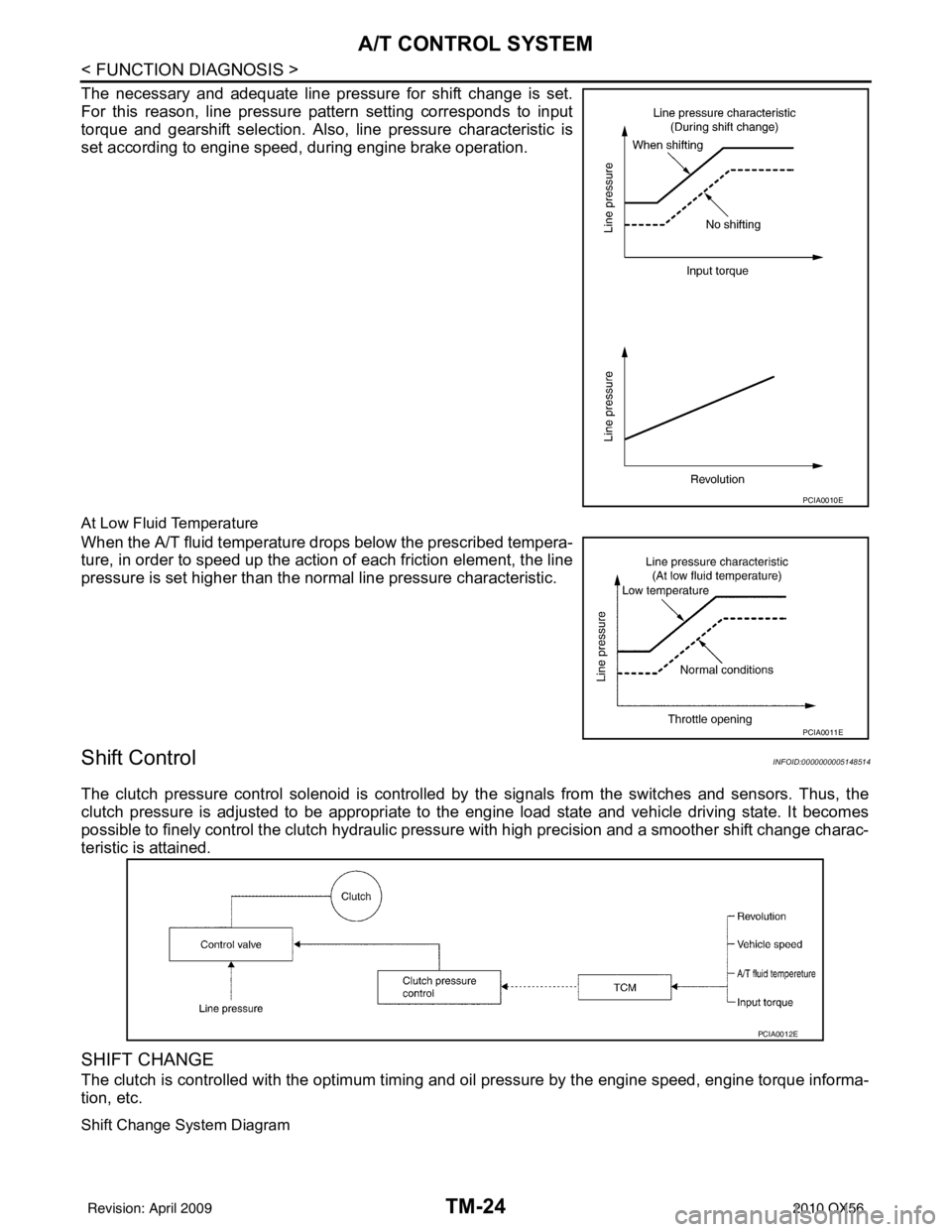
The necessary and adequate line pressure for shift change is set.
For this reason, line pressure pattern setting corresponds to input
torque and gearshift selection. Also, line pressure characteristic is
set according to engine speed, during engine brake operation.
At Low Fluid Temperature
When the A/T fluid temperature drops below the prescribed tempera-
ture, in order to speed up the action of each friction element, the line
pressure is set higher than the normal line pressure characteristic.
Shift ControlINFOID:0000000005148514
The clutch pressure control solenoid is controlled by the signals from the switches and sensors. Thus, the
clutch pressure is adjusted to be appropriate to the engine load state and vehicle driving state. It becomes
possible to finely control the clutch hydraulic pressure with high precision and a smoother shift change charac-
teristic is attained.
SHIFT CHANGE
The clutch is controlled with the optimum timing and oil pressure by the engine speed, engine torque informa-
tion, etc.
Shift Change System Diagram
PCIA0010E
PCIA0011E
PCIA0012E
Revision: April 20092010 QX56
Page 3728 of 4210

DIAGNOSIS SYSTEM (TCM)TM-33
< FUNCTION DIAGNOSIS >
CEF
G H
I
J
K L
M A
B
TM
N
O P
4GR INCORRECT RA-
TIO • A/T cannot shift to 4GR.
P0734 P0734TM-62
5GR INCORRECT RA-
TIO• A/T cannot shift to 5GR.
P0735 P0735TM-64
TORQUE CONVERT-
ER• Normal voltage not applied to solenoid due to cut line,
short, or the like. P0740 P0740
TM-65
TORQUE CONVERT-
ER• A/T cannot perform lock-up even if electrical circuit is
good.
• TCM detects as irregular by comparing difference val-
ue with slip rotation. P0744 P0744*2
TM-68
PC SOLENOID A• Normal voltage not applied to solenoid due to cut line,
short, or the like.
• TCM detects as irregular by comparing target value
with monitor value. P0745 P0745
TM-69
TP SENSOR• TCM does not receive the proper accelerator pedal po-
sition signals (input by CAN communication) from
ECM. P1705 P1705
TM-71
FLUID TEMP SENSOR• During running, the ATF temperature sensor signal
voltage is excessively high or low. P1710 P0710
TM-73
VEHICLE SPEED SIG-
NAL• Signal (CAN communication) from vehicle speed sig-
nal not input due to cut line or the like.
• Unexpected signal input during running. P1721
—TM-76
INTERLOCK • Except during shift change, the gear position and ATF
pressure switch states are monitored and comparative
judgement made. P1730 P1730
TM-78
1GR E/BRAKING• Each ATF pressure switch and solenoid current is
monitored and if a pattern is detected having engine
braking 1GR other than in the "1" position, a malfunc-
tion is detected. P1731
—TM-80
INPUT CLUTCH SOLE-
NOID • Normal voltage not applied to solenoid due to function-
al malfunction, cut line, short, or the like.
• TCM detects as irregular by comparing target value
with monitor value. P1752 P1752
TM-82
FR BRAKE SOLENOID• Normal voltage not applied to solenoid due to function-
al malfunction, cut line, short, or the like.
• TCM detects as irregular by comparing target value
with monitor value. P1757 P1757
TM-84
DRCT CLUTCH SOLE-
NOID• Normal voltage not applied to solenoid due to cut line,
short, or the like.
• TCM detects as irregular by comparing target value
with monitor value. P1762 P1762
TM-86
HLR CLUTCH SOLE-
NOID• Normal voltage not applied to solenoid due to function-
al malfunction, cut line, short, or the like.
• TCM detects as irregular by comparing target value
with monitor value. P1767 P1767
TM-88
L C BRAKE SOLENOID• Normal voltage not applied to solenoid due to function-
al malfunction, cut line, short, or the like. P1772 P1772
TM-90
Items (CONSULT-III
screen terms) Malfunction is detected when... TCM self-di-
agnosis OBD (DTC)
Reference
“TRANSMIS-
SION” with
CONSULT-III MIL indicator
lamp*1, “EN-
GINE” with
CONSULT-III or
GST
Revision: April 20092010 QX56
Page 3729 of 4210

TM-34
< FUNCTION DIAGNOSIS >
DIAGNOSIS SYSTEM (TCM)
*1: Refer to EC-55, "Malfunction Indicator Lamp (MIL)".
*2:These malfunctions cannot be displayed MIL if another malfunction is assigned to MIL.
DATA MONITOR MODE
Display Items List
X: Standard, —: Not applicable
L C BRAKE SOLENOID • TCM detects an improper voltage drop when it tries to
operate the solenoid valve.
• Condition of ATF pressure switch 2 is different from
monitor value, and relation between gear position and
actual gear ratio is irregular. P1774 P1774*2
TM-93
NO DTC IS DETECTED
FURTHER TESTING
MAY BE REQUIRED• No NG item has been detected.
XX —
Items (CONSULT-III
screen terms) Malfunction is detected when... TCM self-di-
agnosis OBD (DTC)
Reference
“TRANSMIS-
SION” with
CONSULT-III MIL indicator
lamp*1, “EN-
GINE” with
CONSULT-III or
GST
Monitored item (Unit) Monitor Item Selection
Remarks
ECU IN-
PUT SIG-
NALS MAIN SIG-
NALS SELEC-
TION
FROM
MENU
VHCL/S SE-A/T (km/h) XXX Output speed sensor
VHCL/S SE-MTR (km/h) X— X —
ACCELE POSI (0.0/8) X— X Accelerator pedal position signal
THROTTLE POSI (0.0/8) XXXDegree of opening for accelerator recognized by
the TCM.
For fail-safe operation, the specific value used
for control is displayed.
CLSD THL POS (ON-OFF display) X— X
Signal input with CAN communications.
W/O THL POS (ON-OFF display) X— X
BRAKESW (ON-OFF display) X— X Stop lamp switch
GEAR —XXGear position recognized by the TCM updated
after gear-shifting.
ENGINE SPEED (rpm) XXX —
INPUT SPEED (rpm) XXX —
OUTPUT REV (rpm) XXX —
GEAR RATIO —XX —
TC SLIP SPEED (rpm) —XXDifference between engine speed and torque
converter input shaft speed.
F SUN GR REV (rpm) —— X —
F CARR GR REV (rpm) —— X —
ATF TEMP SE 1 (V) X— X —
ATF TEMP 1 (° C) —XX —
ATF TEMP 2 (° C) —XX —
BATTERY VOLT (V) X— X —
ATF PRES SW 1 (ON-OFF display) XXX —
ATF PRES SW 2 (ON-OFF display) XXX (for LC/B solenoid)
Revision: April 20092010 QX56
Page 3734 of 4210
DIAGNOSIS SYSTEM (TCM)TM-39
< FUNCTION DIAGNOSIS >
CEF
G H
I
J
K L
M A
B
TM
N
O P
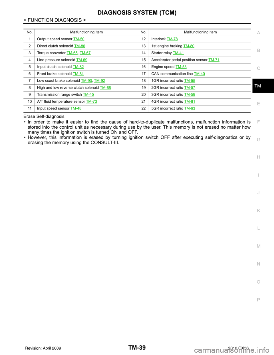
Erase Self-diagnosis
• In order to make it easier to find the cause of
hard-to-duplicate malfunctions, malfunction information is
stored into the control unit as necessary during use by the user. This memory is not erased no matter how
many times the ignition switch is turned ON and OFF.
• However, this information is erased by turning ignition switch OFF after executing self-diagnostics or by erasing the memory using the CONSULT-III.
No. Malfunctioning item No.Malfunctioning item
1 Output speed sensor TM-50
12 Interlock TM-78
2 Direct clutch solenoid TM-8613 1st engine braking TM-80
3 Torque converter TM-65, TM-6714 Starter relay TM-41
4 Line pressure solenoid TM-6915 Accelerator pedal position sensor TM-71
5 Input clutch solenoid TM-8216 Engine speed TM-53
6 Front brake solenoid TM-8417 CAN communication line TM-40
7 Low coast brake solenoid TM-90, TM-9218 1GR incorrect ratio TM-55
8 High and low reverse clutch solenoid TM-8819 2GR incorrect ratio TM-57
9 Transmission range switch TM-4520 3GR incorrect ratio TM-59
10 A/T fluid temperature sensor TM-7321 4GR incorrect ratio TM-61
11 Input speed sensor TM-4822 5GR incorrect ratio TM-63
Revision: April 20092010 QX56
Page 3773 of 4210
TM-78
< COMPONENT DIAGNOSIS >
P1730 INTERLOCK
P1730 INTERLOCK
DescriptionINFOID:0000000005148630
Fail-safe function to detect interlock conditions.
On Board Diagnosis LogicINFOID:0000000005148631
• This is an OBD-II self-diagnostic item.
• Diagnostic trouble code “P1730 INTERLOCK” with CONSUL T-III is detected when TCM does not receive the
proper voltage signal from the sensor and switch.
• TCM monitors and compares gear position and conditions of each ATF pressure switch when gear is steady.
Possible CauseINFOID:0000000005148632
• Harness or connectors (The solenoid and switch circuit is open or shorted.)
• Low coast brake solenoid valve
• ATF pressure switch 2
DTC Confirmation ProcedureINFOID:0000000005148633
NOTE:
If “DTC Confirmation Procedure” has been previously performed, always turn ignition switch “OFF”
and wait at least 10 seconds before performing the next test.
After the repair, perform the following proc edure to confirm the malfunction is eliminated.
WITH CONSULT-III
1. Turn ignition switch “ON”. (Do not start engine.)
2. Select “DATA MONITOR” mode for “TRANSMISSION” with CONSULT-III.
3. Start engine.
4. Drive vehicle and maintain the following conditions for at least 2 consecutive seconds. SLCT LVR POSI: “D” position
5. If DTC is detected, go to TM-78, "
Diagnosis Procedure".
WITH GST
Follow the procedure “With CONSULT-III”.
Judgment of InterlockINFOID:0000000005148634
• When interlock is judged to be malfunctioning, the vehicle should be fixed in 2GR, and should be set in a
condition in which it can travel.
NOTE:
When the vehicle is driven fixed in 2GR, a input speed sensor malfunction is displayed, but this is not a input
speed sensor malfunction.
• When interlock is detected at the 3GR or more, it is locked at the 2GR.
Diagnosis ProcedureINFOID:0000000005148635
1.SELF-DIAGNOSIS
With CONSULT-III
1. Drive vehicle.
2. Stop vehicle and turn ignition switch “OFF”.
3. Turn ignition switch “ON”.
4. Select “SELF-DIAG RESULTS” mode fo r “TRANSMISSION” with CONSULT-III.
OK or NG
OK >> GO TO 2.
NG >> Check low coast brake solenoid valve circuit and function. Refer to TM-90, "
Diagnosis Proce-
dure", TM-93, "Diagnosis Procedure".
2.CHECK DTC
Perform “DTC Confirmation Procedure”.
Revision: April 20092010 QX56