2010 INFINITI QX56 brake sensor
[x] Cancel search: brake sensorPage 2957 of 4210
PG
HARNESSPG-47
< COMPONENT DIAGNOSIS >
C
DE
F
G H
I
J
K L
B A
O P
N
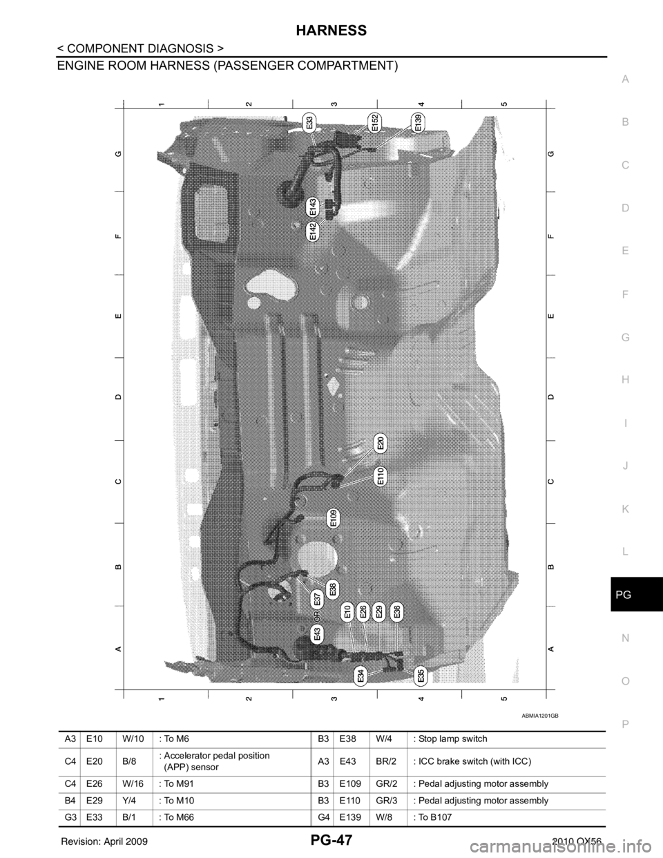
ENGINE ROOM HARNESS (PASSENGER COMPARTMENT)
ABMIA1201GB
A3 E10 W/10 : To M6
B3 E38 W/4 : Stop lamp switch
C4 E20 B/8 : Accelerator pedal position
(APP) sensor
A3 E43 BR/2 : ICC brake switch (with ICC)
C4 E26 W/16 : To M91 B3 E109 GR/2 : Pedal adjusting motor assembly
B4 E29 Y/4 : To M10 B3 E110 GR/3 : Pedal adjusting motor assembly
G3 E33 B/1 : To M66 G4 E139 W/8 : To B107
Revision: April 20092010 QX56
Page 3120 of 4210
RAX-8
< REMOVAL AND INSTALLATION >
WHEEL HUB
REMOVAL AND INSTALLATION
WHEEL HUB
Removal and InstallationINFOID:0000000005148956
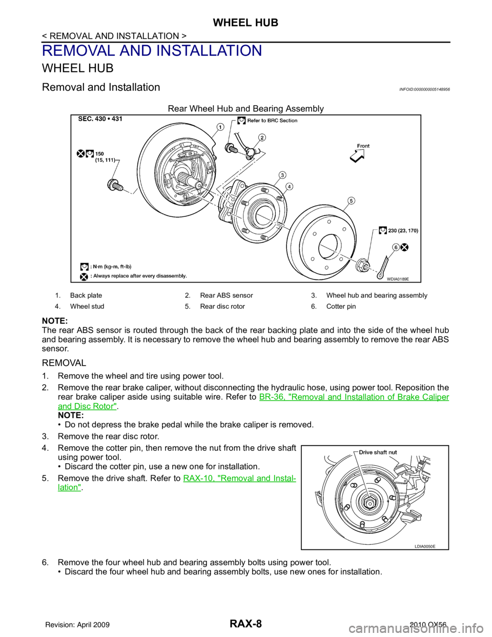
Rear Wheel Hub and Bearing Assembly
NOTE:
The rear ABS sensor is routed through the back of the rear backing plate and into the side of the wheel hub
and bearing assembly. It is necessary to remove the wheel hub and bearing assembly to remove the rear ABS
sensor.
REMOVAL
1. Remove the wheel and tire using power tool.
2. Remove the rear brake caliper, without disconnecting the hydraulic hose, using power tool. Reposition the
rear brake caliper aside using suitable wire. Refer to BR-36, "
Removal and Installation of Brake Caliper
and Disc Rotor".
NOTE:
• Do not depress the brake pedal while the brake caliper is removed.
3. Remove the rear disc rotor.
4. Remove the cotter pin, then remove the nut from the drive shaft using power tool.
• Discard the cotter pin, use a new one for installation.
5. Remove the drive shaft. Refer to RAX-10, "
Removal and Instal-
lation".
6. Remove the four wheel hub and bearing assembly bolts using power tool. • Discard the four wheel hub and bearing assembly bolts, use new ones for installation.
WDIA0189E
1. Back plate 2. Rear ABS sensor3. Wheel hub and be aring assembly
4. Wheel stud 5. Rear disc rotor6. Cotter pin
LDIA0050E
Revision: April 20092010 QX56
Page 3121 of 4210
WHEEL HUBRAX-9
< REMOVAL AND INSTALLATION >
CEF
G H
I
J
K L
M A
B
RAX
N
O P
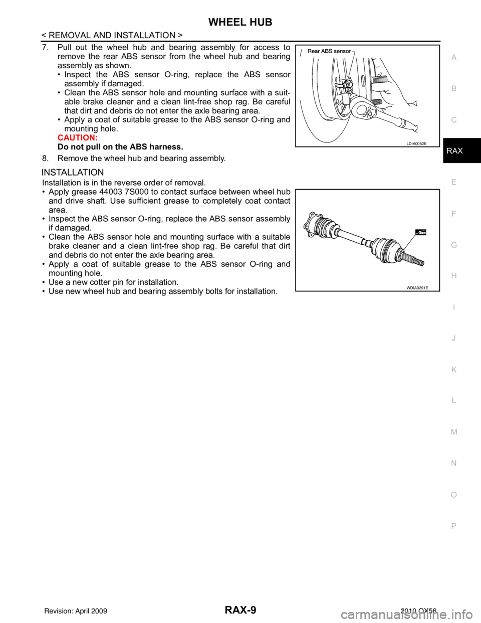
7. Pull out the wheel hub and bearing assembly for access to remove the rear ABS sensor from the wheel hub and bearing
assembly as shown.
• Inspect the ABS sensor O-ri ng, replace the ABS sensor
assembly if damaged.
• Clean the ABS sensor hole and mounting surface with a suit-
able brake cleaner and a clean lint-free shop rag. Be careful
that dirt and debris do not enter the axle bearing area.
• Apply a coat of suitable grease to the ABS sensor O-ring and
mounting hole.
CAUTION:
Do not pull on the ABS harness.
8. Remove the wheel hub and bearing assembly.
INSTALLATION
Installation is in the reverse order of removal.
• Apply grease 44003 7S000 to contact surface between wheel hub and drive shaft. Use sufficient grease to completely coat contact
area.
• Inspect the ABS sensor O-ring, replace the ABS sensor assembly
if damaged.
• Clean the ABS sensor hole and mounting surface with a suitable brake cleaner and a clean lint-free shop rag. Be careful that dirt
and debris do not enter the axle bearing area.
• Apply a coat of suitable grease to the ABS sensor O-ring and mounting hole.
• Use a new cotter pin for installation.
• Use new wheel hub and bearing assembly bolts for installation.
LDIA0052E
WDIA0291E
Revision: April 20092010 QX56
Page 3199 of 4210
RSU-12
< REMOVAL AND INSTALLATION >
REAR SUSPENSION MEMBER
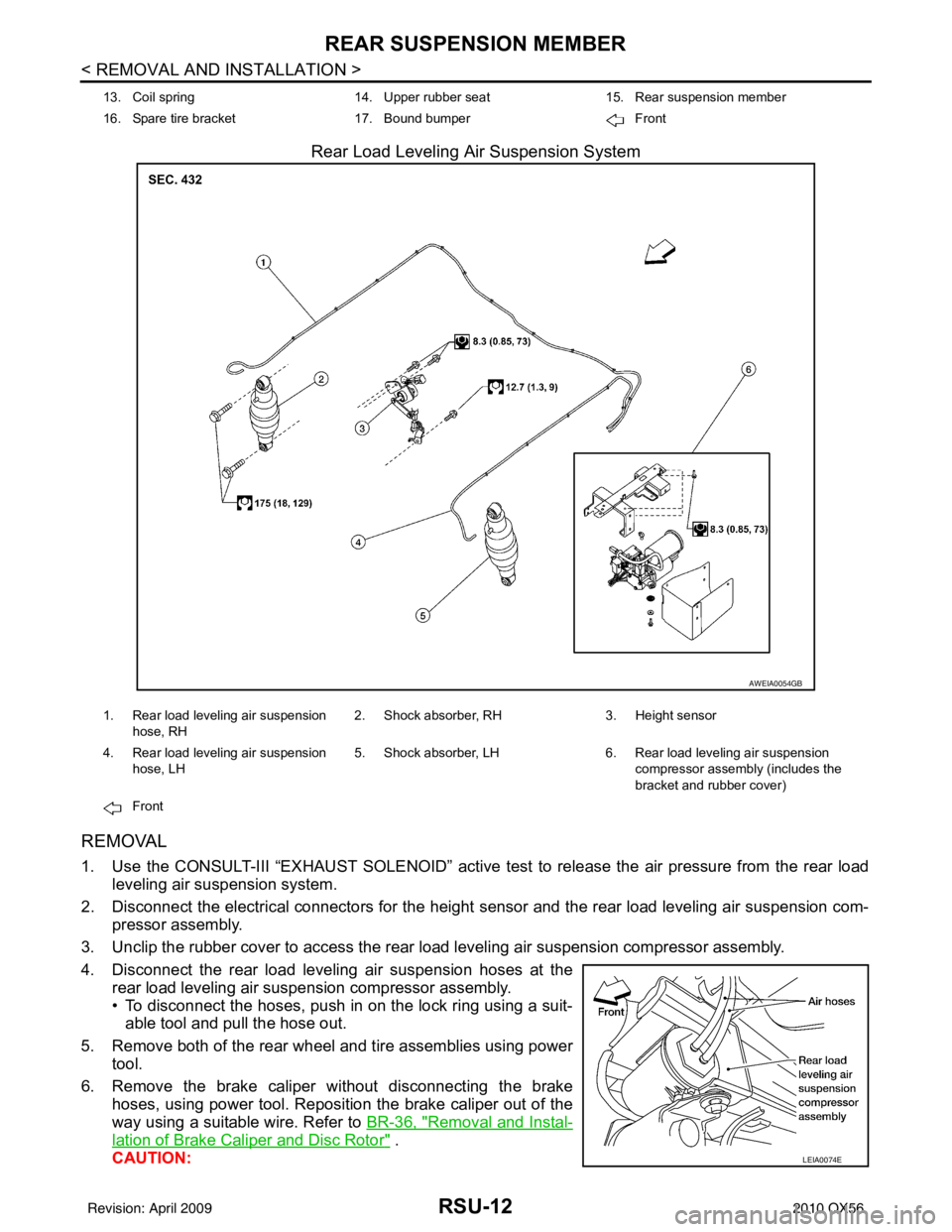
Rear Load Leveling Air Suspension System
REMOVAL
1. Use the CONSULT-III “EXHAUST SOLENOID” active test to release the air pressure from the rear load
leveling air suspension system.
2. Disconnect the electrical connectors for the height sensor and the rear load leveling air suspension com-
pressor assembly.
3. Unclip the rubber cover to access the rear load leveling air suspension compressor assembly.
4. Disconnect the rear load leveling air suspension hoses at the rear load leveling air suspension compressor assembly.
• To disconnect the hoses, push in on the lock ring using a suit-able tool and pull the hose out.
5. Remove both of the rear wheel and tire assemblies using power tool.
6. Remove the brake caliper without disconnecting the brake hoses, using power tool. Reposition the brake caliper out of the
way using a suitable wire. Refer to BR-36, "
Removal and Instal-
lation of Brake Caliper and Disc Rotor" .
CAUTION:
13. Coil spring 14. Upper rubber seat15. Rear suspension member
16. Spare tire bracket 17. Bound bumper Front
AWEIA0054GB
1. Rear load leveling air suspension
hose, RH 2. Shock absorber, RH
3. Height sensor
4. Rear load leveling air suspension hose, LH 5. Shock absorber, LH
6. Rear load leveling air suspension
compressor assembly (includes the
bracket and rubber cover)
Front
LEIA0074E
Revision: April 20092010 QX56
Page 3200 of 4210
REAR SUSPENSION MEMBERRSU-13
< REMOVAL AND INSTALLATION >
C
DF
G H
I
J
K L
M A
B
RSU
N
O P
• Do not crimp or stretch the brake hose when re positioning the brake caliper out of the way.
• Do not press brake pedal while the brake caliper is removed.
7. Remove the spare tire.
8. Disconnect the two rear ABS sensor electrical connectors.
9. Remove the two rear drive shafts. Refer to RAX-10, "
Removal and Installation" .
10. Remove the rear final drive. Refer to DLN-250, "
Removal and Installation" .
11. Remove the EVAP canister bolt from the top of the rear suspension member.
12. Disconnect the parking brake cables from the brackets on the rear suspension member.
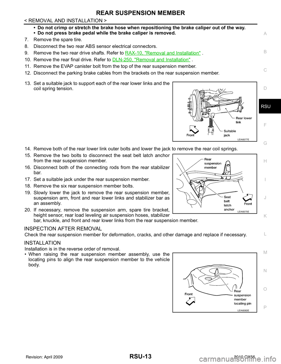
13. Set a suitable jack to support each of the rear lower links and the coil spring tension.
14. Remove both of the rear lower link outer bolts and lower the jack to remove the rear coil springs.
15. Remove the two bolts to disconnect the seat belt latch anchor from the rear suspension member.
16. Disconnect both of the connecting rods from the rear stabilizer
bar.
17. Set a suitable jack under the rear suspension member.
18. Remove the six rear suspension member bolts.
19. Slowly lower the jack to remove the rear suspension member, suspension arm, front and rear lower links and stabilizer bar as
an assembly.
20. If necessary, remove the suspension arm, spare tire bracket, height sensor, rear load leveling air suspension hoses, stabilizer
bar, knuckle, and front and rear lower links from the rear suspension member.
INSPECTION AFTER REMOVAL
Check the rear suspension member for deformation, cracks, and other damage and replace if necessary.
INSTALLATION
Installation is in the reverse order of removal.
• When raising the rear suspension member assembly, use the
locating pins to align the rear suspension member to the vehicle
body.
LEIA0077E
LEIA0075E
LEIA0083E
Revision: April 20092010 QX56
Page 3477 of 4210
SN
INSPECTION AND ADJUSTMENTSN-5
< BASIC INSPECTION >
C
DE
F
G H
I
J
K L
M B A
O P
INSPECTION AND ADJUSTMENT
Preliminary CheckINFOID:0000000005146183
DESCRIPTION
The purpose of the sonar sensor preliminary check is to confirm that there are no outside factors affecting the
sonar system.
CONDITIONS
• Ignition switch ON
• No obstructions within 3.0 m (10 ft.) of sonar sensors
SONAR SENSOR STATUS CHECK
• Check that the sonar sensors are properly aligned (no deformation in sensor mounting areas).
• Check that snow, mud or other foreign obj ects are not adhering to the sonar sensors.
• Check that there is no deformation, scratc hes or other damage to the sonar sensors.
• Check that water has not accu mulated in the sonar sensors.
CAUTION:
Use water, cotton swab, or other soft material for cleaning the sensors.
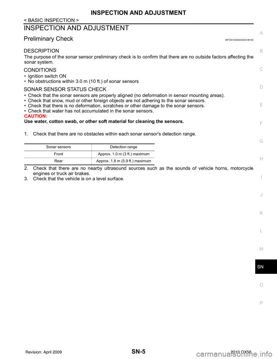
1. Check that there are no obstacles wit hin each sonar sensor's detection range.
2. Check that there are no nearby ultrasound sources such as the sounds of vehicle horns, motorcycle
engines or truck air brakes.
3. Check that the vehicle is on a level surface.
Sonar sensors Detection range
Front Approx. 1.0 m (3 ft.) maximum
Rear Approx. 1.8 m (5.9 ft.) maximum
Revision: April 20092010 QX56
Page 3696 of 4210
TM-1
TRANSMISSION & DRIVELINE
CEF
G H
I
J
K L
M
SECTION TM
A
B
TM
N
O P
CONTENTS
TRANSAXLE & TRANSMISSION
BASIC INSPECTION ....... .............................5
DIAGNOSIS AND REPAIR WORKFLOW ..... .....5
Work Flow ........................................................... ......5
Diagnostic Work Sheet ..............................................6
FUNCTION DIAGNOSIS ...............................8
A/T CONTROL SYSTEM ................................ .....8
Cross-Sectional View (2WD models) .................. ......8
Cross-Sectional View (4WD models) ........................9
Shift Mechanism ........................................................9
TCM Function ..........................................................20
CAN Communication ...............................................21
Input/Output Signal of TCM .....................................22
Line Pressure Control .............................................22
Shift Control ........................................................ ....24
Lock-up Control .......................................................25
Engine Brake Control ..............................................26
Control Valve ...........................................................26
Component Parts Location ......................................28
A/T SHIFT LOCK SYSTEM ............................ ....29
System Description ............................................. ....29
Component Parts Location ......................................29
ON BOARD DIAGNOSTIC (OBD) SYSTEM ......30
Introduction ......................................................... ....30
OBD-II Function for A/T System ..............................30
One or Two Trip Detection Logic of OBD-II ............30
OBD-II Diagnostic Trouble Code (DTC) ..................30
Malfunction Indicator Lamp (MIL) ............................31
DIAGNOSIS SYSTEM (TCM) .............................32
CONSULT-III Function (TRANSMISSION) ......... ....32
Diagnosis Procedure without CONSULT-III ........ ....37
COMPONENT DIAGNOSIS .........................40
U1000 CAN COMM CI RCUIT .............................40
Description .......................................................... ....40
On Board Diagnosis Logic ......................................40
Possible Cause .................................................... ....40
DTC Confirmation Procedure ..................................40
Diagnosis Procedure ...............................................40
P0615 STARTER RELAY .................................41
Description ...............................................................41
CONSULT-III Reference Value in Data Monitor
Mode .................................................................... ....
41
On Board Diagnosis Logic .......................................41
Possible Cause ........................................................41
DTC Confirmation Procedure ..................................41
Diagnosis Procedure ...............................................41
P0700 TRANSMISSION CONTROL .................44
Description ...............................................................44
On Board Diagnosis Logic .......................................44
Possible Cause ........................................................44
DTC Confirmation Procedure ..................................44
Diagnosis Procedure ...............................................44
P0705 TRANSMISSION RANGE SWITCH A ...45
Description ...............................................................45
CONSULT-III Reference Value in Data Monitor
Mode .................................................................... ....
45
On Board Diagnosis Logic .......................................45
Possible Cause ........................................................45
DTC Confirmation Procedure ..................................45
Diagnosis Procedure ...............................................45
P0717 INPUT SPEED SENSOR A ....................48
Description ...............................................................48
CONSULT-III Reference Value in Data Monitor
Mode .................................................................... ....
48
On Board Diagnosis Logic .......................................48
Possible Cause ........................................................48
DTC Confirmation Procedure ..................................48
Diagnosis Procedure ...............................................48
P0720 OUTPUT SPEED SENSOR ...................50
Description ...............................................................50
CONSULT-III Reference Value in Data Monitor
Mode .................................................................... ....
50
Revision: April 20092010 QX56
Page 3699 of 4210

TM-4
STALL TEST ....................................................155
Inspection and Judgment .................................... ..155
LINE PRESSURE TEST ..................................157
Inspection and Judgment .................................... ..157
ROAD TEST .....................................................159
Description ........................................................... ..159
Check Before Engine Is Started ............................159
Check At Idle ....................................................... ..159
Cruise Test - Part 1 ...............................................160
Cruise Test - Part 2 ...............................................162
Cruise Test - Part 3 ...............................................162
Vehicle Speed When Shifting Gears .....................163
Vehicle Speed When Performing and Releasing
Complete Lock-up .................................................
163
A/T POSITION .................................................164
Adjustment of A/T Position .................................. ..164
Checking of A/T Position .......................................164
ON-VEHICLE REPAIR ...............................165
SHIFT CONTROL SYSTEM ........................... .165
A/T Shift Selector Removal and Installation ..........165
AIR BREATHER HOSE .................................. .166
Removal and Installation ..................................... ..166
OIL PAN ...........................................................170
Oil Pan ................................................................. ..170
CONTROL VALVE WITH TCM ........................172
Control Valve with TCM and A/T Fluid Tempera-
ture Sensor 2 and Plug ........................................ ..
172
REAR OIL SEAL ..............................................184
Rear Oil Seal ....................................................... ..184
FLUID COOLER SYSTEM ...............................185
Exploded View ..................................................... ..185
Removal and Installation .......................................185
REMOVAL AND INSTALLATION ..............186
TRANSMISSION ASSEMBLY ........................ .186
Removal and Installation (2WD) .......................... .186
Removal and Installation (4WD) ...........................188
DISASSEMBLY AND ASSEMBLY ...........192
OVERHAUL ......................................................192
Component .......................................................... .192
Oil Channel ...........................................................199
Location of Adjusting Shims, Needle Bearings,
Thrust Washers and Snap Rings ......................... .
201
DISASSEMBLY .............................................. ..204
Disassembly ......................................................... .204
REPAIR FOR COMPONENT PARTS ..............223
Oil Pump .............................................................. .223
Front Sun Gear, 3rd One-Way Clutch ...................225
Front Carrier, Input Clutch, Rear Internal Gear .....227
Mid Sun Gear, Rear Sun Gear, High and Low Re-
verse Clutch Hub ................................................. .
232
High and Low Reverse Clutch ..............................237
Direct Clutch .........................................................239
ASSEMBLY .................................................... ..242
Assembly (1) ........................................................ .242
Adjustment ............................................................255
Assembly (2) .........................................................257
SERVICE DATA AND SPECIFICATIONS
(SDS) ........ .................................................
265
SERVICE DATA AND SPECIFICATIONS
(SDS) .............................................................. ..
265
General Specification ........................................... .265
Vehicle Speed at Which Gear Shifting Occurs .....265
Vehicle Speed at Which Lock-up Occurs/Releas-
es ......................................................................... .
266
Stall Speed ............................................................266
Line Pressure ........................................................266
Input Speed Sensor ..............................................266
Output Speed Sensor ...........................................266
Reverse Brake ......................................................266
Total End Play .......................................................267
Torque Converter ..................................................267
Revision: April 20092010 QX56