2010 INFINITI QX56 brake sensor
[x] Cancel search: brake sensorPage 3853 of 4210
TM-158
< ON-VEHICLE MAINTENANCE >
LINE PRESSURE TEST
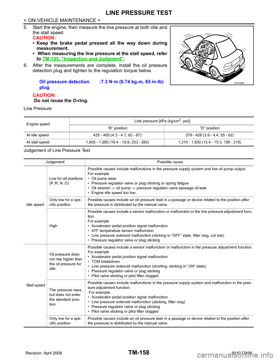
5. Start the engine, then measure the line pressure at both idle andthe stall speed.
CAUTION:
• Keep the brake pedal pressed all the way down duringmeasurement.
• When measuring the line pressure at the stall speed, refer
to TM-155, "
Inspection and Judgment".
6. After the measurements are complete, install the oil pressure detection plug and tighten to the regulation torque below.
CAUTION:
Do not reuse the O-ring.
Line Pressure
Judgement of Line Pressure Test
Oil pressure detection
plug :7.3 N·m (0.74 kg-m, 65 in-lb)SAT493G
Engine speed
Line pressure [kPa (kg/cm
2, psi)]
“R” position “D” position
At idle speed 425 - 465 (4.3 - 4.7, 62 - 67) 379 - 428 (3.9 - 4.4, 55 - 62)
At stall speed 1,605 - 1,950 (16.4 - 19.9, 233 - 283) 1,310 - 1,500 (13.4 - 15.3, 190 - 218)
Judgement Possible cause
Idle speed Low for all positions
(P, R, N, D)
Possible causes include malfunctions in the pressure supply system and low oil pump output.
For example
•Oil pump wear
• Pressure regulator valve or plug sticking or spring fatigue
• Oil strainer ⇒ oil pump
⇒ pressure regulator valve passage oil leak
• Engine idle speed too low
Only low for a spe-
cific position Possible causes include an oil pressure leak in a passage or device related to the position after
the pressure is distributed by the manual valve.
High Possible causes include a sensor malfunction or malfunction in the line pressure adjustment func-
tion.
For example
• Accelerator pedal position signal malfunction
• ATF temperature sensor malfunction
• Line pressure solenoid malfunction (sticking in “OFF” state, filter clog, cut line)
• Pressure regulator valve or plug sticking
Sta ll sp ee d Oil pressure does
not rise higher than
the oil pressure for
idle.
Possible causes include a sensor malfunction or malfunction in the pressure adjustment function.
For example
• Accelerator pedal position signal malfunction
• TCM breakdown
• Line pressure solenoid malfunction (shorting, sticking in“ ON” state)
• Pressure regulator valve or plug sticking
• Pilot valve sticking or pilot filter clogged
The pressure rises,
but does not enter
the standard posi-
tion. Possible causes include malfunctions in the pressure supply system and malfunction in the pres-
sure adjustment function.
For example
• Accelerator pedal position signal malfunction
• Line pressure solenoid malfunction (sticking, filter clog)
• Pressure regulator valve or plug sticking
• Pilot valve sticking or pilot filter clogged
Only low for a spe-
cific position Possible causes include an oil pressure leak in a passage or device related to the position after
the pressure is distributed by the manual valve.
Revision: April 20092010 QX56
Page 3873 of 4210
TM-178
< ON-VEHICLE REPAIR >
CONTROL VALVE WITH TCM
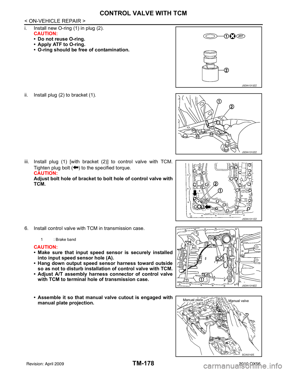
i. Install new O-ring (1) in plug (2).CAUTION:
• Do not reuse O-ring.
• Apply ATF to O-ring.
• O-ring should be free of contamination.
ii. Install plug (2) to bracket (1).
iii. Install plug (1) [with bracket (2)] to control valve with TCM. Tighten plug bolt ( ) to the specified torque.
CAUTION:
Adjust bolt hole of bracket to bolt hole of control valve with
TCM.
6. Install control valve with TCM in transmission case. CAUTION:
• Make sure that input speed sensor is securely installedinto input speed sensor hole (A).
• Hang down output speed sen sor harness toward outside
so as not to disturb installati on of control valve with TCM.
• Adjust A/T assembly harness co nnector of control valve
with TCM to terminal hole of transmission case.
• Assemble it so that manual valve cutout is engaged with manual plate projection.
JSDIA1313ZZ
JSDIA1312ZZ
JSDIA1311ZZ
1 : Brake band
JSDIA1318ZZ
SCIA5142E
Revision: April 20092010 QX56
Page 3912 of 4210
DISASSEMBLYTM-217
< DISASSEMBLY AND ASSEMBLY >
CEF
G H
I
J
K L
M A
B
TM
N
O P
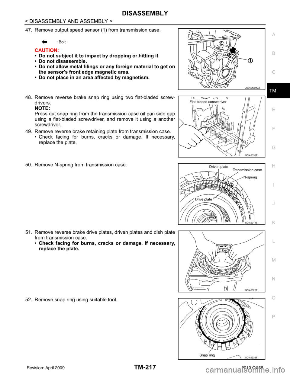
47. Remove output speed sensor (1) from transmission case.
CAUTION:
• Do not subject it to impact by dropping or hitting it.
• Do not disassemble.
• Do not allow metal filings or any foreign material to get onthe sensor's front edge magnetic area.
• Do not place in an area affected by magnetism.
48. Remove reverse brake snap ring using two flat-bladed screw- drivers.
NOTE:
Press out snap ring from the transmission case oil pan side gap
using a flat-bladed screwdriver, and remove it using a another
screwdriver.
49. Remove reverse brake retaining plate from transmission case. • Check facing for burns, cracks or damage. If necessary,
replace the plate.
50. Remove N-spring from transmission case.
51. Remove reverse brake drive plates, driven plates and dish plate from transmission case.
•Check facing for burns, cracks or damage. If necessary,
replace the plate.
52. Remove snap ring using suitable tool.
: Bolt
JSDIA1321ZZ
SCIA5032E
SCIA5214E
SCIA2322E
SCIA2323E
Revision: April 20092010 QX56
Page 3956 of 4210
![INFINITI QX56 2010 Factory Service Manual ASSEMBLYTM-261
< DISASSEMBLY AND ASSEMBLY >
CEF
G H
I
J
K L
M A
B
TM
N
O P
iii. Install plug (1) [with bracket (2)] to control valve with TCM and tighten bolt ( ) to specified torque.
CAUTION:
Adjust INFINITI QX56 2010 Factory Service Manual ASSEMBLYTM-261
< DISASSEMBLY AND ASSEMBLY >
CEF
G H
I
J
K L
M A
B
TM
N
O P
iii. Install plug (1) [with bracket (2)] to control valve with TCM and tighten bolt ( ) to specified torque.
CAUTION:
Adjust](/manual-img/42/57032/w960_57032-3955.png)
ASSEMBLYTM-261
< DISASSEMBLY AND ASSEMBLY >
CEF
G H
I
J
K L
M A
B
TM
N
O P
iii. Install plug (1) [with bracket (2)] to control valve with TCM and tighten bolt ( ) to specified torque.
CAUTION:
Adjust bolt hole of bracket to bolt hole of control valve.
14. Install control valve with TCM in transmission case. CAUTION:
• Make sure that input speed sensor is securely installed
into input speed sensor hole (A).
• Hang down output speed sensor harness toward outside so as not to disturb installati on of control valve with TCM.
• Adjust A/T assembly harness connector of control valve
with TCM to terminal hole of transmission case.
• Assemble it so that manual valve cutout is engaged with
manual plate projection.
15. Install bolts (A), (B) and (C) to control valve with TCM.
16. Tighten bolt (A), (B) and (C) temporarily to prevent dislocation. After that tighten them in order (A → B → C), and then tighten
other bolts. Bracket bolt : 7.9 N·m (0.81 kg-m, 70 in-lb)
JSDIA1311ZZ
1 : Brake band
JSDIA1318ZZ
SCIA5035E
: Front
Bolt symbol Length mm (in) Number of bolts
A 42 (1.65) 5
B 55 (2.17) 6
C 40 (1.57) 1
SCIA8077E
: Front
Bolt symbol A B C
Number of bolts 5 6 1
Length mm (in) 42 (1.65) 55 (2.17) 40 (1.57)
SCIA8078E
Revision: April 20092010 QX56
Page 3961 of 4210

TM-266
< SERVICE DATA AND SPECIFICATIONS (SDS)
SERVICE DATA AND SPECIFICATIONS (SDS)
• At half throttle, the accelerator opening is 1/2 of the full opening.
Vehicle Speed at Which Lock-up Occurs/ReleasesINFOID:0000000005148760
• At closed throttle, the accelerator opening is less than 1/8 condition. (Closed throttle position signal OFF)
• At half throttle, the accelerator opening is 1/2 of the full opening.
Stall SpeedINFOID:0000000005148761
Line PressureINFOID:0000000005148762
Input Speed SensorINFOID:0000000005148763
Output Speed SensorINFOID:0000000005148764
Reverse BrakeINFOID:0000000005148765
3.357Full throttle
61 - 65
(38 - 41) 97 - 105
(61 - 66) 153 - 163
(95 - 102) 236 - 246
(147 - 153) 232 - 242
(144 - 151) 143 - 153
(89 - 95) 87 - 95
(54 - 59) 43 - 47
(27 - 29)
Half throttle 46 - 50
(29 - 31) 73 - 79
(45 - 59) 99 - 107
(62 - 66) 119 - 127
(74 - 79) 97 - 105
(60 - 65) 65 - 73
(40 - 45) 39 - 45
(24 - 28) 11 - 1 5
(7 - 10)
Final gear ratio Throttle position Vehicle speed km/h (MPH)
Lock-up ON Lock-up OFF
2.937 Closed throttle
51 - 59 (32 - 36) 48 - 56 (30 - 34)
Half throttle 177 - 185 (110 - 115) 111 - 119 (69 - 73)
3.357 Closed throttle
44 - 52 (28 - 32) 41 - 49 (26 - 30)
Half throttle 161 - 169 (100 - 105) 97 - 105 (61 - 65)
Stall speed 2,550 - 2,850 rpm
Engine speedLine pressure kPa (kg/cm
2, psi)
“R” position “D” position
At idle speed 425 – 465 (4.3 – 4.7, 62 – 67) 379 – 428 (3.9 – 4.4, 55 – 62)
At stall speed 1,605 – 1,950 (16.4 – 19.9, 233 – 283) 1,310 – 1,500 (13.4 – 15.3, 190 – 218)
Name ConditionData (Approx.)
Input speed sensor 1 When running at 50 km/h (31 MPH) in 4th speed witch the closed throttle position
signal OFF.
1.3 kHz
Input speed sensor 2 When running at 20 km/h (12 MPH) in 1st speed witch the closed throttle position
signal OFF.
Name
ConditionData (Approx.)
Output speed sensor When running at 20 km/h (12 MPH). 185 Hz
Number of drive plates 7
Number of driven plates 7
Clearance mm (in) Standard 0.7 – 1.1 (0.028 – 0.043)
Revision: April 20092010 QX56
Page 4027 of 4210
WCS-28
< ECU DIAGNOSIS >
COMBINATION METER
ECU DIAGNOSIS
COMBINATION METER
Reference ValueINFOID:0000000005382408
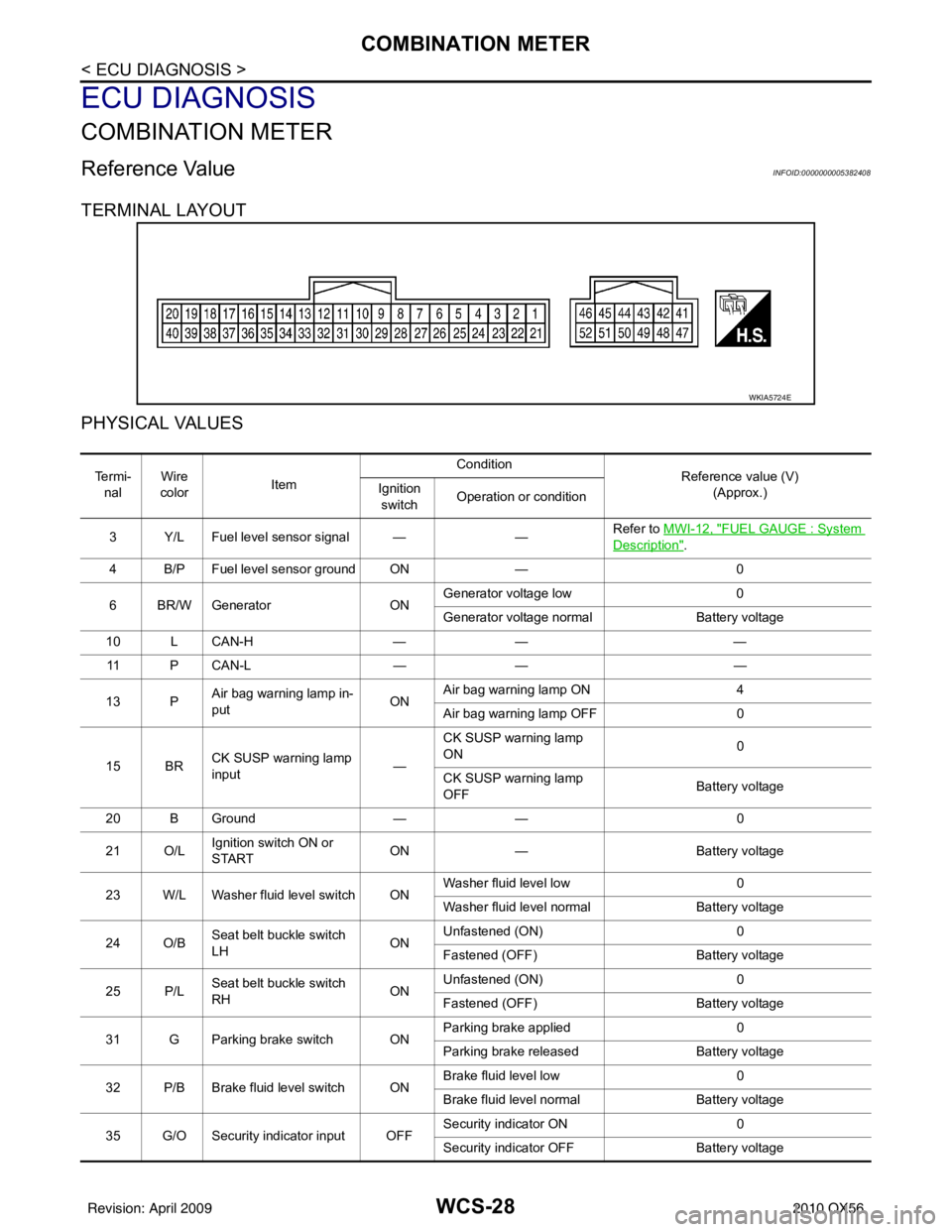
TERMINAL LAYOUT
PHYSICAL VALUES
WKIA5724E
Te r m i -nal Wire
color Item Condition
Reference value (V)
(Approx.)
Ignition
switch Operation or condition
3 Y/L Fuel level sensor signal — —Refer to MWI-12, "
FUEL GAUGE : System
Description".
4 B/P Fuel level sensor ground ON —0
6 BR/W Generator ONGenerator voltage low
0
Generator voltage normal Battery voltage
10 L CAN-H —— —
11 P C A N - L —— —
13 P Air bag warning lamp in-
put ONAir bag warning lamp ON
4
Air bag warning lamp OFF 0
15 BR CK SUSP warning lamp
input —CK SUSP warning lamp
ON
0
CK SUSP warning lamp
OFF Battery voltage
20 B Ground —— 0
21 O/L Ignition switch ON or
START ON
— Battery voltage
23 W/L Washer fluid level switch ON Washer fluid level low
0
Washer fluid level normal Battery voltage
24 O/B Seat belt buckle switch
LH ONUnfastened (ON)
0
Fastened (OFF) Battery voltage
25 P/L Seat belt buckle switch
RH ONUnfastened (ON)
0
Fastened (OFF) Battery voltage
31 G Parking brake switch ON Parking brake applied
0
Parking brake released Battery voltage
32 P/B Brake fluid level switch ON Brake fluid level low
0
Brake fluid level normal Battery voltage
35 G/O Security indicator input OFF Security indicator ON
0
Security indicator OFF Battery voltage
Revision: April 20092010 QX56
Page 4068 of 4210
WCS
PRECAUTIONSWCS-69
< PRECAUTION >
C
DE
F
G H
I
J
K L
M B A
O P
PRECAUTION
PRECAUTIONS
Precaution for Supplemental Restraint System (SRS) "AIR BAG" and "SEAT BELT
PRE-TENSIONER"
INFOID:0000000005238466
The Supplemental Restraint System such as “AIR BAG” and “SEAT BELT PRE-TENSIONER”, used along
with a front seat belt, helps to reduce the risk or severi ty of injury to the driver and front passenger for certain
types of collision. This system includes seat belt switch inputs and dual stage front air bag modules. The SRS
system uses the seat belt switches to determine the front air bag deployment, and may only deploy one front
air bag, depending on the severity of a collision and w hether the front occupants are belted or unbelted.
Information necessary to service the system safely is included in the SR and SB section of this Service Man-
ual.
WARNING:
• To avoid rendering the SRS inoper ative, which could increase the risk of personal injury or death in
the event of a collision which would result in air bag inflation, all maintenance must be performed by
an authorized NISSAN/INFINITI dealer.
• Improper maintenance, including in correct removal and installation of the SRS, can lead to personal
injury caused by unintentional act ivation of the system. For removal of Spiral Cable and Air Bag
Module, see the SR section.
• Do not use electrical test equipm ent on any circuit related to the SRS unless instructed to in this
Service Manual. SRS wiring harnesses can be identi fied by yellow and/or orange harnesses or har-
ness connectors.
PRECAUTIONS WHEN USING POWER TOOLS (AIR OR ELECTRIC) AND HAMMERS
WARNING:
• When working near the Airbag Diagnosis Sensor Un it or other Airbag System sensors with the Igni-
tion ON or engine running, DO NOT use air or el ectric power tools or strike near the sensor(s) with a
hammer. Heavy vibration could activate the sensor( s) and deploy the air bag(s), possibly causing
serious injury.
• When using air or electric power tools or hammers, always switch the Ignition OFF, disconnect the battery, and wait at least 3 minutes before performing any service.
Necessary for Steering Wheel Ro tation After Battery DisconnectINFOID:0000000005238467
NOTE:
• Before removing and installing any control units, first tu rn the push-button ignition switch to the LOCK posi-
tion, then disconnect both battery cables.
• After finishing work, confirm that all control unit connectors are connected properly, then re-connect both
battery cables.
• Always use CONSULT-III to perform self-diagnosis as a part of each function inspection after finishing work.
If a DTC is detected, perform trouble diagnos is according to self-diagnosis results.
This vehicle is equipped with a push-button ignition switch and a steering lock unit.
If the battery is disconnect ed or discharged, the steering wheel will lock and cannot be turned.
If turning the steering wheel is required with the battery disconnected or discharged, follow the procedure
below before starting the repair operation.
OPERATION PROCEDURE
1. Connect both battery cables. NOTE:
Supply power using jumper cables if battery is discharged.
2. Carry the Intelligent Key or insert it to the key slot and turn the push-button ignition switch to ACC position. (At this time, the steering lock will be released.)
3. Disconnect both battery cables. The steering lock will remain released with both battery cables discon- nected and the steering wheel can be turned.
4. Perform the necessary repair operation.
5. When the repair work is completed, re-connect both battery cables. With the brake pedal released, turn the push-button ignition switch from ACC position to ON position, then to LOCK position. (The steering
wheel will lock when the push-button ignition switch is turned to LOCK position.)
Revision: April 20092010 QX56