Page 3776 of 4210

P1731 1ST ENGINE BRAKINGTM-81
< COMPONENT DIAGNOSIS >
CEF
G H
I
J
K L
M A
B
TM
N
O P
OK or NG
OK >> GO TO 4.
NG >> GO TO 2.
2.CHECK TCM POWER SUPPLY AND GROUND CIRCUIT
Check TCM power supply and ground circuit. Refer to TM-94, "
Diagnosis Procedure".
OK or NG
OK >> GO TO 3.
NG >> Repair or replace damaged parts.
3.DETECT MALFUNCTIONING ITEM
Check the following items:
• The A/T assembly harness connector pin terminals for damage or loose connection with harness connector.
OK or NG
OK >> Replace the control valve with TCM. Refer to TM-172, "Control Valve with TCM and A/T Fluid
Temperature Sensor 2 and Plug".
NG >> Repair or replace damaged parts.
4.CHECK DTC
Perform “DTC Confirmation Procedure”.
• Refer to TM-80, "
DTC Confirmation Procedure".
OK or NG
OK >> INSPECTION END
NG >> GO TO 2.
Item name Condition Display value
ON OFF SOL Low coast brake engaged. Refer to
TM-9
.O N
Low coast brake disengaged. Refer to TM-9
.O FF
ATF PRES SW 2 Low coast brake engaged. Refer to
TM-9
.O N
Low coast brake disengaged. Refer to TM-9
.O FF
Revision: April 20092010 QX56
Page 3780 of 4210

P1757 FRONT BRAKE SOLENOIDTM-85
< COMPONENT DIAGNOSIS >
CEF
G H
I
J
K L
M A
B
TM
N
O P
OK or NG
OK >> GO TO 4.
NG >> GO TO 2.
2.CHECK TCM POWER SUPPLY AND GROUND CIRCUIT
Check TCM power supply and ground circuit. Refer to TM-94, "
Diagnosis Procedure".
OK or NG
OK >> GO TO 3.
NG >> Repair or replace damaged parts.
3.DETECT MALFUNCTIONING ITEM
Check the following items:
• The A/T assembly harness connector pin terminals for damage or loose connection with harness connector.
OK or NG
OK >> Replace the control valve with TCM. Refer to TM-172, "Control Valve with TCM and A/T Fluid
Temperature Sensor 2 and Plug".
NG >> Repair or replace damaged parts.
4.CHECK DTC
Perform “DTC Confirmation Procedure”.
• Refer to TM-84, "
DTC Confirmation Procedure".
OK or NG
OK >> INSPECTION END
NG >> GO TO 2.
Item name Condition Display value (Approx.)
FR/B SOLENOID Front brake engaged. Refer to TM-9
.
0.6 - 0.8 A
Front brake disengaged. Refer to TM-9
. 0 - 0.05 A
Revision: April 20092010 QX56
Page 3786 of 4210
P1772 LOW COAST BRAKE SOLENOIDTM-91
< COMPONENT DIAGNOSIS >
CEF
G H
I
J
K L
M A
B
TM
N
O P
NG >> GO TO 2.
2.CHECK TCM POWER SUPPLY AND GROUND CIRCUIT
Check TCM power supply and ground circuit. Refer to TM-94, "
Diagnosis Procedure".
OK or NG
OK >> GO TO 3.
NG >> Repair or replace damaged parts.
3.DETECT MALFUNCTIONING ITEM
Check the following items:
• The A/T assembly harness connector pin terminals for damage or loose connection with harness connector.
OK or NG
OK >> Replace the control valve with TCM. Refer to TM-172, "Control Valve with TCM and A/T Fluid
Temperature Sensor 2 and Plug".
NG >> Repair or replace damaged parts.
4.CHECK DTC
Perform “DTC Confirmation Procedure”.
• Refer to TM-90, "
DTC Confirmation Procedure".
OK or NG
OK >> INSPECTION END
NG >> GO TO 2.
Revision: April 20092010 QX56
Page 3788 of 4210
P1774 LOW COAST BRAKE SOLENOIDTM-93
< COMPONENT DIAGNOSIS >
CEF
G H
I
J
K L
M A
B
TM
N
O P
Diagnosis ProcedureINFOID:0000000005148677
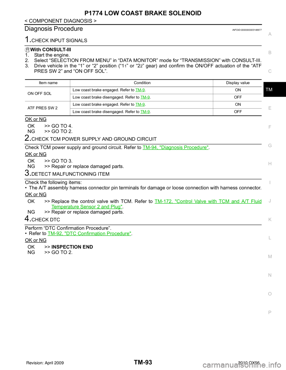
1.CHECK INPUT SIGNALS
With CONSULT-III
1. Start the engine.
2. Select “SELECTION FROM MENU” in “DATA MONI TOR” mode for “TRANSMISSION” with CONSULT-III.
3. Drive vehicle in the “1” or “2” position (“1
1” or “22” gear) and confirm the ON/OFF actuation of the “ATF
PRES SW 2” and “ON OFF SOL”.
OK or NG
OK >> GO TO 4.
NG >> GO TO 2.
2.CHECK TCM POWER SUPPLY AND GROUND CIRCUIT
Check TCM power supply and ground circuit. Refer to TM-94, "
Diagnosis Procedure".
OK or NG
OK >> GO TO 3.
NG >> Repair or replace damaged parts.
3.DETECT MALFUNCTIONING ITEM
Check the following items:
• The A/T assembly harness connector pin terminals for damage or loose connection with harness connector.
OK or NG
OK >> Replace the control valve with TCM. Refer to TM-172, "Control Valve with TCM and A/T Fluid
Temperature Sensor 2 and Plug".
NG >> Repair or replace damaged parts.
4.CHECK DTC
Perform “DTC Confirmation Procedure”.
• Refer to TM-92, "
DTC Confirmation Procedure".
OK or NG
OK >> INSPECTION END
NG >> GO TO 2.
Item name Condition Display value
ON OFF SOL Low coast brake engaged. Refer to
TM-9
.O N
Low coast brake disengaged. Refer to TM-9
.O FF
ATF PRES SW 2 Low coast brake engaged. Refer to
TM-9
.O N
Low coast brake disengaged. Refer to TM-9
.O FF
Revision: April 20092010 QX56
Page 3814 of 4210
TCM
TM-119
< ECU DIAGNOSIS >
C EF
G H
I
J
K L
M A
B
TM
N
O P
High and Low Revers
e Clutch Solenoid
• If a (electrical or functional) malfunction occurs with the solenoid either “ON” or “OFF”, the transmission is
held in 4GR to make driving possible.
Input Speed Sensor 1 or 2
• The control is the same as if there were no input speed sensors, 5GR is prohibited.
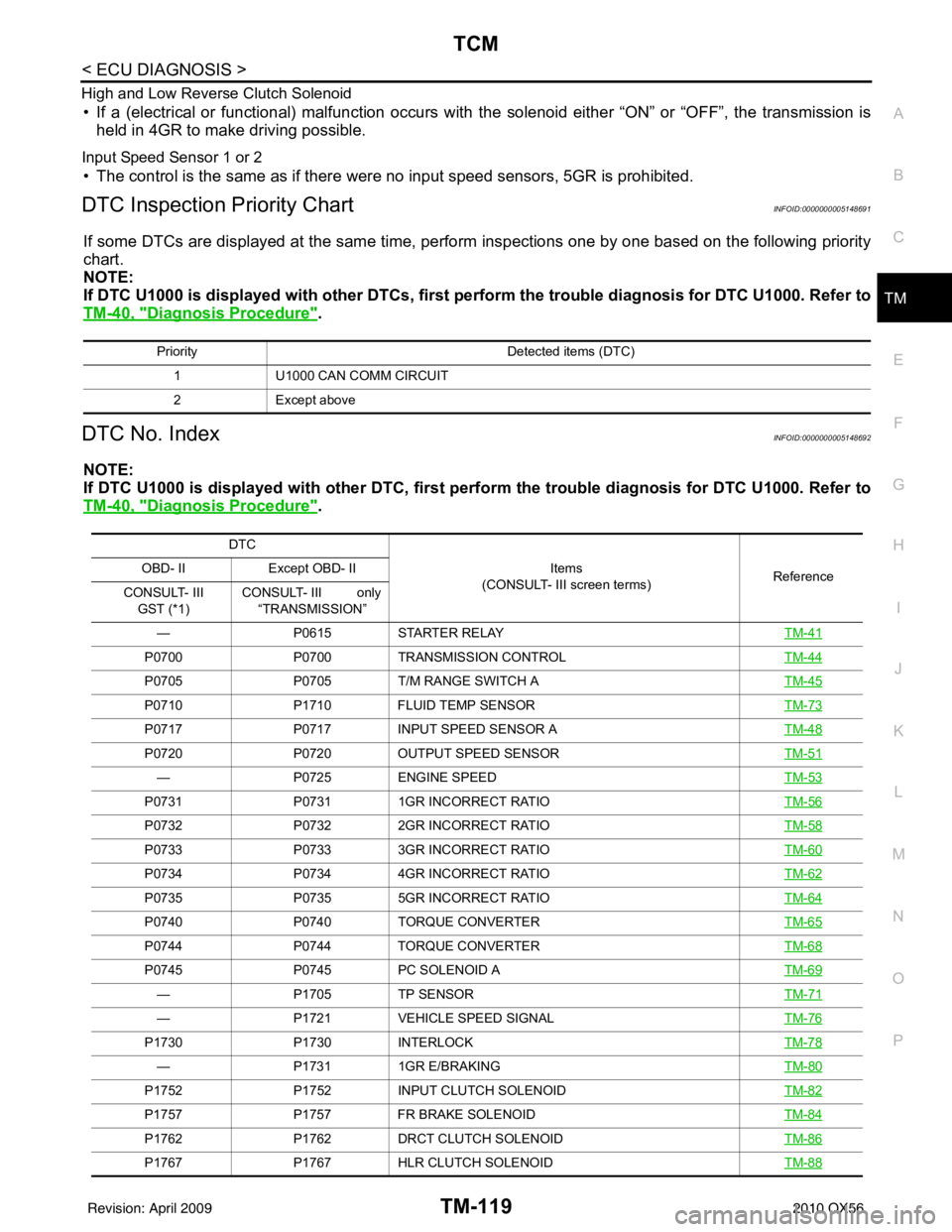
DTC Inspection Priority ChartINFOID:0000000005148691
If some DTCs are displayed at the same time, perform inspections one by one based on the following priority
chart.
NOTE:
If DTC U1000 is displayed with other DTCs, first pe rform the trouble diagnosis for DTC U1000. Refer to
TM-40, "
Diagnosis Procedure".
DTC No. IndexINFOID:0000000005148692
NOTE:
If DTC U1000 is displayed with other DTC, first pe rform the trouble diagnosis for DTC U1000. Refer to
TM-40, "
Diagnosis Procedure".
Priority Detected items (DTC)
1 U1000 CAN COMM CIRCUIT
2 Except above
DTC
Items
(CONSULT- III screen terms) Reference
OBD- II
Except OBD- II
CONSULT- III GST (*1) CONSULT- III only
“TRANSMISSION”
— P0615STARTER RELAY TM-41
P0700P0700TRANSMISSION CONTROL TM-44
P0705P0705T/M RANGE SWITCH A TM-45
P0710P1710FLUID TEMP SENSOR TM-73
P0717P0717INPUT SPEED SENSOR A TM-48
P0720P0720OUTPUT SPEED SENSOR TM-51
—P0725ENGINE SPEED TM-53
P0731P07311GR INCORRECT RATIO TM-56
P0732P07322GR INCORRECT RATIO TM-58
P0733P07333GR INCORRECT RATIO TM-60
P0734P07344GR INCORRECT RATIO TM-62
P0735P07355GR INCORRECT RATIO TM-64
P0740P0740TORQUE CONVERTER TM-65
P0744 P0744 TORQUE CONVERTER TM-68
P0745P0745PC SOLENOID A TM-69
—P1705TP SENSOR TM-71
—P1721VEHICLE SPEED SIGNAL TM-76
P1730P1730INTERLOCK TM-78
—P17311GR E/BRAKING TM-80
P1752P1752INPUT CLUTCH SOLENOID TM-82
P1757P1757FR BRAKE SOLENOID TM-84
P1762P1762DRCT CLUTCH SOLENOID TM-86
P1767P1767HLR CLUTCH SOLENOID TM-88
Revision: April 20092010 QX56
Page 3815 of 4210
TM-120
< ECU DIAGNOSIS >
TCM
*1: These numbers are prescribed by SAE J2012.
*2: These malfunctions cannot be displayed MIL if another malfunction is assigned to MIL.
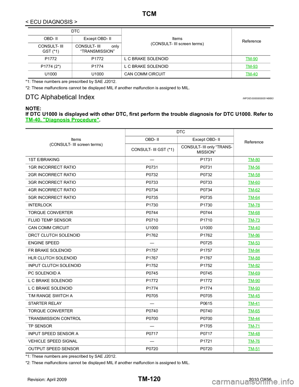
DTC Alphabetical IndexINFOID:0000000005148693
NOTE:
If DTC U1000 is displayed with other DTC, first perform the trouble diagnosis for DTC U1000. Refer to
TM-40, "
Diagnosis Procedure".
*1: These numbers are prescribed by SAE J2012.
*2: These malfunctions cannot be displayed MIL if another malfunction is assigned to MIL. P1772
P1772L C BRAKE SOLENOID TM-90
P1774 (2*) P1774 L C BRAKE SOLENOID TM-93
U1000U1000CAN COMM CIRCUIT TM-40
DTC
Items
(CONSULT- III screen terms) Reference
OBD- II
Except OBD- II
CONSULT- III GST (*1) CONSULT- III only
“TRANSMISSION”
Items
(CONSULT- III screen terms) DTC
Reference
OBD- II
Except OBD- II
CONSULT- III GST (*1) CONSULT- III only “TRANS-
MISSION”
1ST E/BRAKING —P1731TM-80
1GR INCORRECT RATIO P0731P0731TM-56
2GR INCORRECT RATIO P0732P0732TM-58
3GR INCORRECT RATIO P0733P0733TM-60
4GR INCORRECT RATIO P0734P0734TM-62
5GR INCORRECT RATIO P0735P0735TM-64
INTERLOCK P1730P1730TM-78
TORQUE CONVERTER P0744 P0744 TM-68
FLUID TEMP SENSOR P0710P1710TM-73
CAN COMM CIRCUIT U1000U1000TM-40
DRCT CLUTCH SOLENOID P1762P1762 TM-86
ENGINE SPEED —P0725TM-53
FR BRAKE SOLENOID P1757P1757TM-84
HLR CLUTCH SOLENOID P1767P1767TM-88
INPUT CLUTCH SOLENOID P1752P1752TM-82
PC SOLENOID A P0745P0745TM-69
L C BRAKE SOLENOID P1772P1772TM-90
L C BRAKE SOLENOID P1774 P1774 TM-93
T/M RANGE SWITCH A P0705P0705TM-45
STARTER RELAY —P0615TM-41
TORQUE CONVERTER P0740P0740TM-65
TRANSMISSION CONTROL P0700P0700TM-44
TP SENSOR —P1705TM-71
INPUT SPEED SENSOR A P0717P0717TM-48
VEHICLE SPEED SIGNAL —P1721TM-76
OUTPUT SPEED SENSOR P0720P0720TM-51
Revision: April 20092010 QX56
Page 3816 of 4210
SYSTEM SYMPTOMTM-121
< SYMPTOM DIAGNOSIS >
CEF
G H
I
J
K L
M A
B
TM
N
O P
SYMPTOM DIAGNOSIS
SYSTEM SYMPTOM
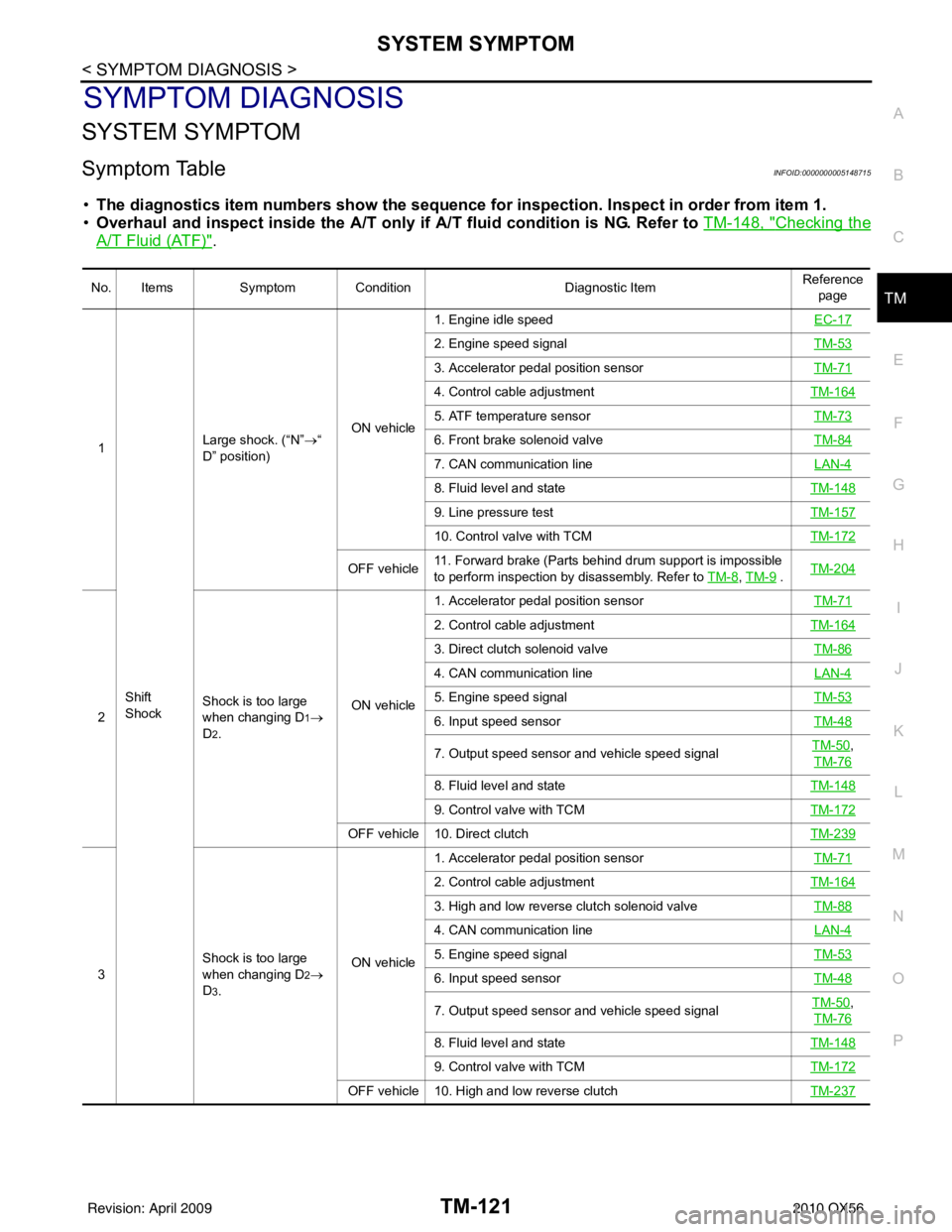
Symptom TableINFOID:0000000005148715
• The diagnostics item numbers s how the sequence for inspection. Inspect in order from item 1.
• Overhaul and inspect inside the A/T only if A/T fluid condition is NG. Refer to TM-148, "
Checking the
A/T Fluid (ATF)".
No. ItemsSymptom Condition Diagnostic ItemReference
page
1
Shift
Shock Large shock. (“N”
→“
D” position) ON vehicle1. Engine idle speed
EC-17
2. Engine speed signalTM-53
3. Accelerator pedal position sensorTM-71
4. Control cable adjustmentTM-164
5. ATF temperature sensor TM-73
6. Front brake solenoid valveTM-84
7. CAN communication line LAN-4
8. Fluid level and stateTM-148
9. Line pressure testTM-157
10. Control valve with TCMTM-172
OFF vehicle11. Forward brake (Parts behind drum support is impossible
to perform inspection by disassembly. Refer to
TM-8, TM-9 . TM-204
2 Shock is too large
when changing D1→
D
2. ON vehicle1. Accelerator pedal position sensor
TM-71
2. Control cable adjustmentTM-164
3. Direct clutch solenoid valve TM-86
4. CAN communication line LAN-4
5. Engine speed signalTM-53
6. Input speed sensorTM-48
7. Output speed sensor and vehicle speed signalTM-50,
TM-76
8. Fluid level and state TM-148
9. Control valve with TCMTM-172
OFF vehicle 10. Direct clutch TM-239
3Shock is too large
when changing D2→
D
3. ON vehicle1. Accelerator pedal position sensor
TM-71
2. Control cable adjustmentTM-164
3. High and low reverse clutch solenoid valve TM-88
4. CAN communication line LAN-4
5. Engine speed signalTM-53
6. Input speed sensorTM-48
7. Output speed sensor and vehicle speed signalTM-50,
TM-76
8. Fluid level and state TM-148
9. Control valve with TCMTM-172
OFF vehicle 10. High and low reverse clutch TM-237
Revision: April 20092010 QX56
Page 3817 of 4210
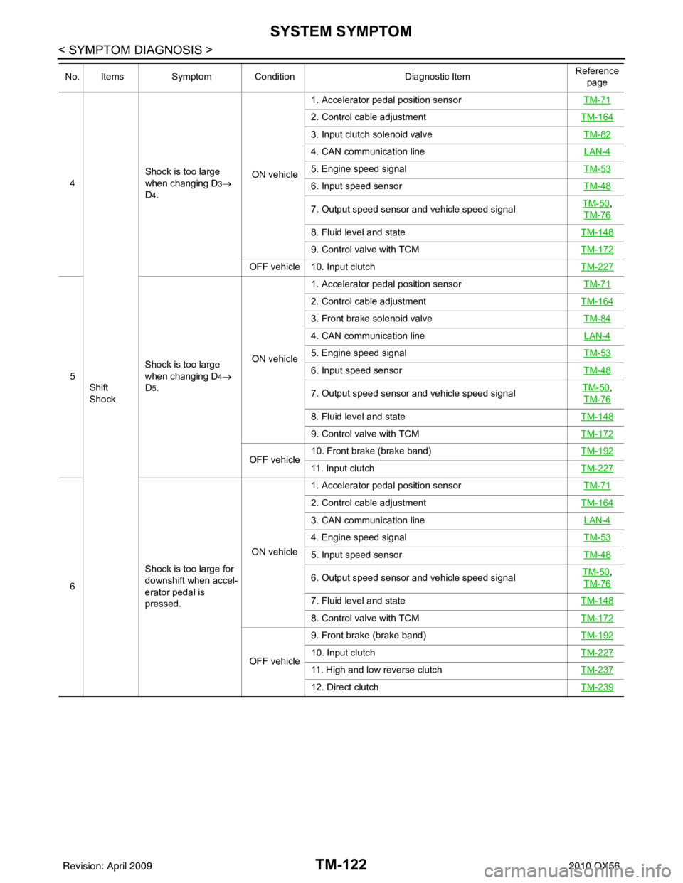
TM-122
< SYMPTOM DIAGNOSIS >
SYSTEM SYMPTOM
4Shift
Shock Shock is too large
when changing D3→
D
4. ON vehicle1. Accelerator pedal position sensor
TM-71
2. Control cable adjustmentTM-164
3. Input clutch solenoid valve TM-82
4. CAN communication line LAN-4
5. Engine speed signalTM-53
6. Input speed sensorTM-48
7. Output speed sensor and vehicle speed signalTM-50,
TM-76
8. Fluid level and state TM-148
9. Control valve with TCMTM-172
OFF vehicle 10. Input clutch TM-227
5Shock is too large
when changing D4→
D
5. ON vehicle1. Accelerator pedal position sensor
TM-71
2. Control cable adjustmentTM-164
3. Front brake solenoid valve TM-84
4. CAN communication line LAN-4
5. Engine speed signalTM-53
6. Input speed sensorTM-48
7. Output speed sensor and vehicle speed signalTM-50,
TM-76
8. Fluid level and state TM-148
9. Control valve with TCMTM-172
OFF vehicle10. Front brake (brake band)
TM-19211. Input clutchTM-227
6Shock is too large for
downshift when accel-
erator pedal is
pressed. ON vehicle1. Accelerator pedal position sensor
TM-71
2. Control cable adjustmentTM-164
3. CAN communication line LAN-4
4. Engine speed signalTM-53
5. Input speed sensorTM-48
6. Output speed sensor and vehicle speed signalTM-50,
TM-76
7. Fluid level and state TM-148
8. Control valve with TCMTM-172
OFF vehicle9. Front brake (brake band)
TM-19210. Input clutchTM-227
11. High and low reverse clutchTM-237
12. Direct clutchTM-239
No. ItemsSymptom Condition Diagnostic ItemReference
page
Revision: April 20092010 QX56