2010 INFINITI QX56 brake fluid
[x] Cancel search: brake fluidPage 2764 of 4210

MWI-2
INFORMATION DISPLAY .........................................19
INFORMATION DISPLAY : System Diagram .........20
INFORMATION DISPLAY : System Description ....20
INFORMATION DISPLAY : Component Parts Lo-
cation ................................................................... ...
21
INFORMATION DISPLAY : Component Descrip-
tion ....................................................................... ...
21
DIAGNOSIS SYSTEM (METER) .......................22
Diagnosis Description .......................................... ...22
CONSULT-III Function (METER/M&A) ................ ...23
COMPONENT DIAGNOSIS ........................26
DTC U1000 CAN COMMUNICATION ............ ...26
DTC Logic ............................................................ ...26
Diagnosis Procedure .............................................26
DTC B2205 VEHICLE SPEED CIRCUIT ...........27
Description ........................................................... ...27
DTC Logic ...............................................................27
Diagnosis Procedure .............................................27
POWER SUPPLY AND GROUND CIRCUIT .....28
COMBINATION METER ........................................ ...28
COMBINATION METER : Diagnosis Procedure ....28
BCM (BODY CONTROL MODULE) ...................... ...29
BCM (BODY CONTROL MODULE) : Diagnosis
Procedure ...............................................................
29
IPDM E/R (INTELLIGENT POWER DISTRIBU-
TION MODULE ENGINE ROOM) .......................... ...
30
IPDM E/R (INTELLIGENT POWER DISTRIBU-
TION MODULE ENGINE ROOM) : Diagnosis Pro-
cedure .....................................................................
30
FUEL LEVEL SENSOR SIGNAL CIRCUIT .......32
Description ........................................................... ...32
Component Function Check ...................................32
Diagnosis Procedure .............................................32
Component Inspection ............................................33
OIL PRESSURE SWITCH SIGNAL CIRCUIT ...34
Description ..............................................................34
Component Function Check ...................................34
Diagnosis Procedure ..............................................34
Component Inspection ............................................34
PARKING BRAKE SWITCH SIGNAL CIR-
CUIT ...................................................................
35
Description ........................................................... ...35
Component Function Check ...................................35
Diagnosis Procedure ..............................................35
Component Inspection ............................................35
WASHER LEVEL SWITCH SIGNAL CIRCUIT ...36
Description ........................................................... ...36
Diagnosis Procedure ..............................................36
Component Inspection ............................................36
CLOCK ..............................................................37
Wiring Diagram .................................................... ...37
ECU DIAGNOSIS .......................................39
COMBINATION METER ................................. ...39
Reference Value .................................................. ...39
Wiring Diagram .......................................................41
Fail Safe ..................................................................58
DTC Index ...............................................................59
BCM (BODY CONTROL MODULE) ..................61
Reference Value .................................................. ...61
Terminal Layout ......................................................64
Physical Values .......................................................64
Wiring Diagram .......................................................70
Fail Safe .................................................................74
DTC Inspection Priority Chart ...............................75
DTC Index ..............................................................75
IPDM E/R (INTELLIGENT POWER DISTRI-
BUTION MODULE ENGINE ROOM) .................
77
Reference Value .................................................. ...77
Terminal Layout ......................................................79
Physical Values .......................................................80
Wiring Diagram .......................................................85
Fail Safe .................................................................88
DTC Index ..............................................................90
SYMPTOM DIAGNOSIS ............................91
THE FUEL GAUGE POINTER DOES NOT
MOVE .............................................................. ...
91
Description ........................................................... ...91
Diagnosis Procedure ...............................................91
THE FUEL GAUGE POINTER DOES NOT
MOVE TO "F" WHEN REFUELING ..................
92
Description ........................................................... ...92
Diagnosis Procedure ...............................................92
THE OIL PRESSURE WARNING LAMP
DOES NOT TURN ON .................................... ...
93
Description ........................................................... ...93
Diagnosis Procedure ...............................................93
THE OIL PRESSURE WARNING LAMP
DOES NOT TURN OFF .................................. ...
94
Description ........................................................... ...94
Diagnosis Procedure ...............................................94
THE PARKING BRAKE RELEASE WARNING
CONTINUES DISPLAYING, OR DOES NOT
DISPLAY ............................................................
95
Description ........................................................... ...95
Diagnosis Procedure ...............................................95
THE LOW WASHER FLUID WARNING CON-
TINUES DISPLAYING, or DOES NOT DIS-
PLAY ..................................................................
96
Revision: April 20092010 QX56
Page 2770 of 4210
MWI-8
< FUNCTION DIAGNOSIS >
METER SYSTEM
SPEEDOMETER
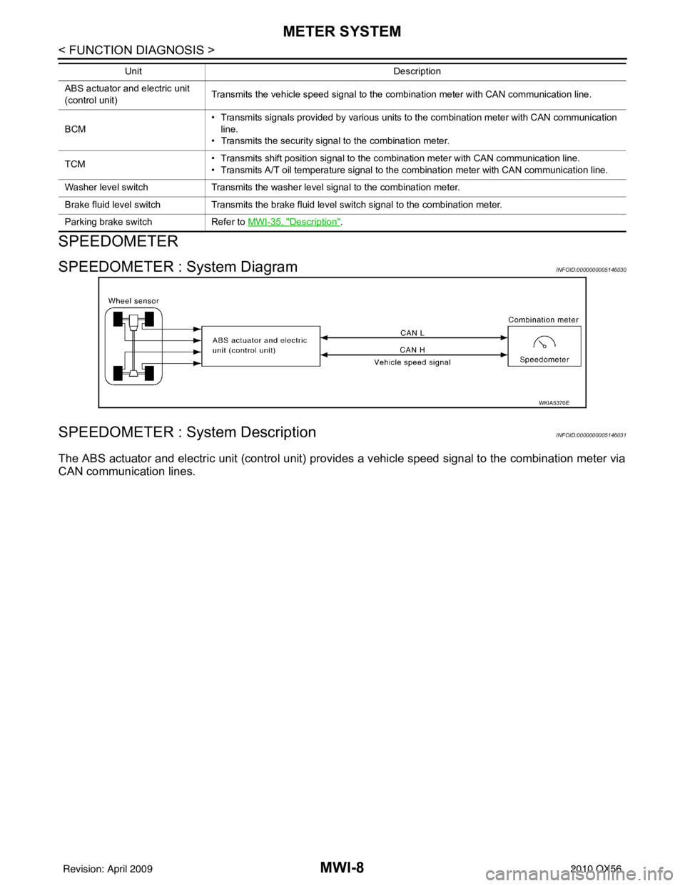
SPEEDOMETER : System DiagramINFOID:0000000005146030
SPEEDOMETER : System DescriptionINFOID:0000000005146031
The ABS actuator and electric unit (control unit) provides a vehicle speed signal to the combination meter via
CAN communication lines.
ABS actuator and electric unit
(control unit) Transmits the vehicle speed signal to the combination meter with CAN communication line.
BCM • Transmits signals provided by various units to the combination meter with CAN communication
line.
• Transmits the security signal to the combination meter.
TCM • Transmits shift position signal to the combination meter with CAN communication line.
• Transmits A/T oil temperature signal to the combination meter with CAN communication line.
Washer level switch Transmits the washer level signal to the combination meter.
Brake fluid level switch Transmits the brake fluid level switch signal to the combination meter.
Parking brake switch Refer to MWI-35, "
Description".
Unit
Description
WKIA5370E
Revision: April 20092010 QX56
Page 2782 of 4210
MWI-20
< FUNCTION DIAGNOSIS >
METER SYSTEM
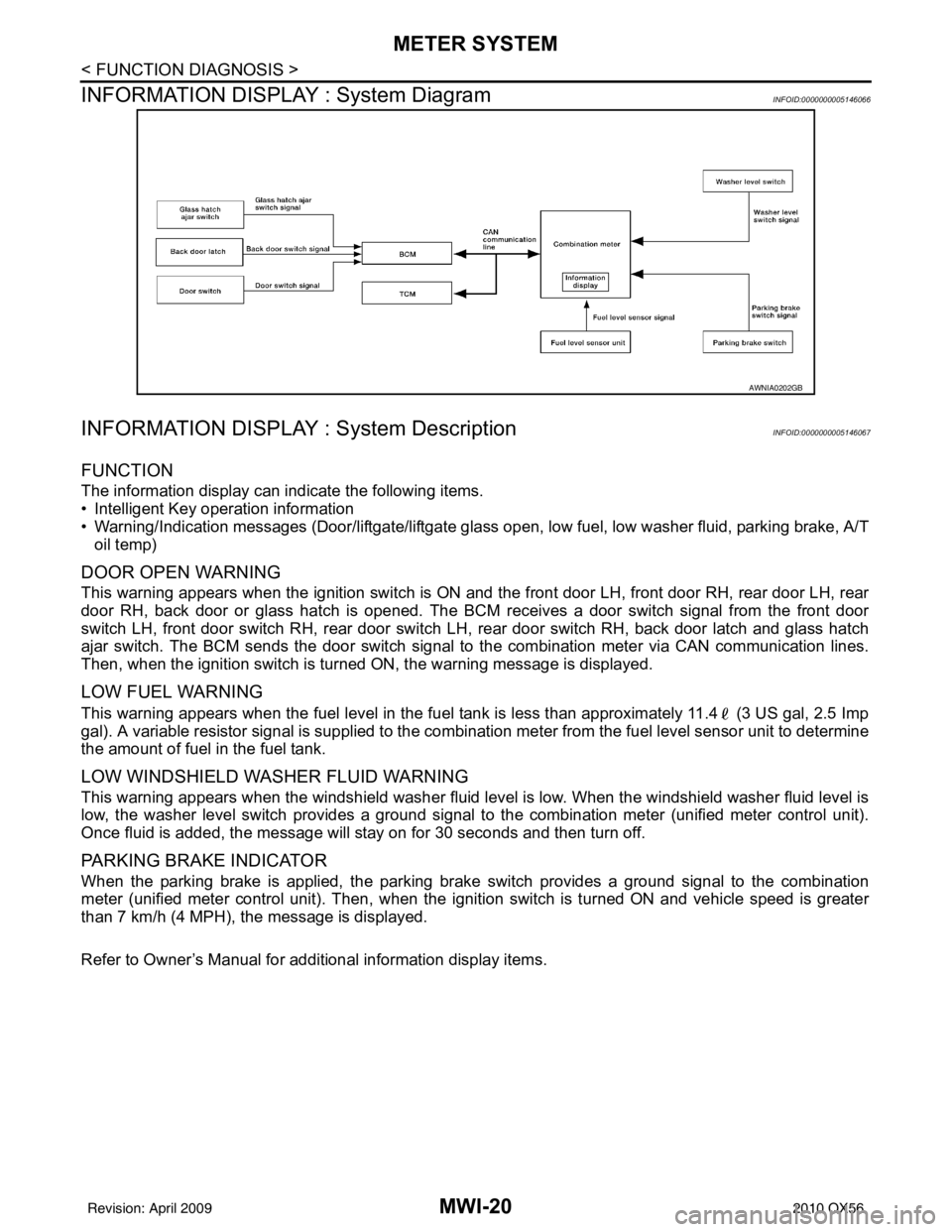
INFORMATION DISPLAY : System Diagram
INFOID:0000000005146066
INFORMATION DISPLAY : System DescriptionINFOID:0000000005146067
FUNCTION
The information display can indicate the following items.
• Intelligent Key operation information
• Warning/Indication messages (Door/liftgate/liftgate glass open, low fuel, low washer fluid, parking brake, A/T
oil temp)
DOOR OPEN WARNING
This warning appears when the ignition switch is ON and the front door LH, front door RH, rear door LH, rear
door RH, back door or glass hatch is opened. The BCM receives a door switch signal from the front door
switch LH, front door switch RH, rear door switch LH, rear door switch RH, back door latch and glass hatch
ajar switch. The BCM sends the door switch signal to the combination meter via CAN communication lines.
Then, when the ignition switch is turned ON, the warning message is displayed.
LOW FUEL WARNING
This warning appears when the fuel level in the fuel tank is less than approximately 11.4 (3 US gal, 2.5 Imp
gal). A variable resistor signal is supplied to the combination meter from the fuel level sensor unit to determine
the amount of fuel in the fuel tank.
LOW WINDSHIELD WASHER FLUID WARNING
This warning appears when the windshield washer fluid level is low. When the windshield washer fluid level is
low, the washer level switch provides a ground signal to the combination meter (unified meter control unit).
Once fluid is added, the message will stay on for 30 seconds and then turn off.
PARKING BRAKE INDICATOR
When the parking brake is applied, the parking brake switch provides a ground signal to the combination
meter (unified meter control unit). Then, when the igni tion switch is turned ON and vehicle speed is greater
than 7 km/h (4 MPH), the message is displayed.
Refer to Owner’s Manual for additional information display items.
AWNIA0202GB
Revision: April 20092010 QX56
Page 2787 of 4210
MWI
DIAGNOSIS SYSTEM (METER)MWI-25
< FUNCTION DIAGNOSIS >
C
DE
F
G H
I
J
K L
M B A
O P
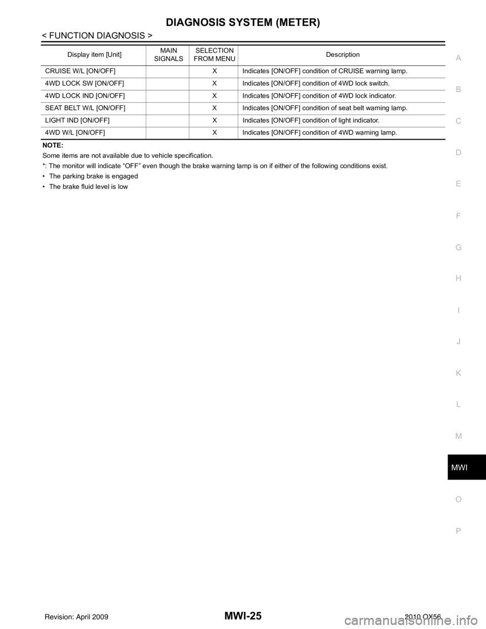
NOTE:
Some items are not available due to vehicle specification.
*: The monitor will indicate “OFF” even though the brake warnin g lamp is on if either of the following conditions exist.
• The parking brake is engaged
• The brake fluid level is low CRUISE W/L [ON/OFF]
X Indicates [ON/OFF] condition of CRUISE warning lamp.
4WD LOCK SW [ON/OFF] X Indicates [ON/OFF] condition of 4WD lock switch.
4WD LOCK IND [ON/OFF] X Indicates [ON/OFF] condition of 4WD lock indicator.
SEAT BELT W/L [ON/OFF] X Indicates [ON/OFF] condition of seat belt warning lamp.
LIGHT IND [ON/OFF] X Indicates [ON/OFF] condition of light indicator.
4WD W/L [ON/OFF] X Indicates [ON/OFF] condition of 4WD warning lamp.
Display item [Unit]
MAIN
SIGNALS SELECTION
FROM MENU Description
Revision: April 20092010 QX56
Page 2801 of 4210
MWI
COMBINATION METERMWI-39
< ECU DIAGNOSIS >
C
DE
F
G H
I
J
K L
M B A
O P
ECU DIAGNOSIS
COMBINATION METER
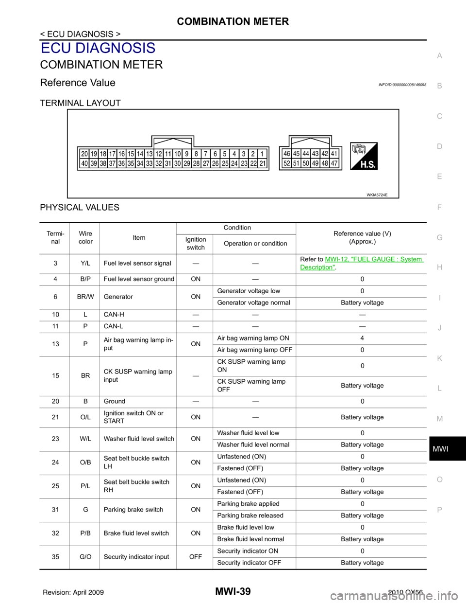
Reference ValueINFOID:0000000005146098
TERMINAL LAYOUT
PHYSICAL VALUES
WKIA5724E
Te r m i - nal Wire
color Item Condition
Reference value (V)
(Approx.)
Ignition
switch Operation or condition
3 Y/L Fuel level sensor signal — —Refer to
MWI-12, "
FUEL GAUGE : System
Description".
4 B/P Fuel level sensor ground ON —0
6 BR/W Generator ONGenerator voltage low
0
Generator voltage normal Battery voltage
10 L CAN-H —— —
11 P C A N - L —— —
13 P Air bag warning lamp in-
put ONAir bag warning lamp ON
4
Air bag warning lamp OFF 0
15 BR CK SUSP warning lamp
input —CK SUSP warning lamp
ON
0
CK SUSP warning lamp
OFF Battery voltage
20 B Ground —— 0
21 O/L Ignition switch ON or
START ON
— Battery voltage
23 W/L Washer fluid level switch ON Washer fluid level low
0
Washer fluid level normal Battery voltage
24 O/B Seat belt buckle switch
LH ONUnfastened (ON)
0
Fastened (OFF) Battery voltage
25 P/L Seat belt buckle switch
RH ONUnfastened (ON)
0
Fastened (OFF) Battery voltage
31 G Parking brake switch ON Parking brake applied
0
Parking brake released Battery voltage
32 P/B Brake fluid level switch ON Brake fluid level low
0
Brake fluid level normal Battery voltage
35 G/O Security indicator input OFF Security indicator ON
0
Security indicator OFF Battery voltage
Revision: April 20092010 QX56
Page 2956 of 4210

PG-46
< COMPONENT DIAGNOSIS >
HARNESS
D4 E6 B/8: Front combination lamp LH (with
daytime light system) C1 E119 W/16: IPDM E/R (intelligent power distribution
module engine room)
C2 E7 GR/2 : Fusible link box (battery) D1 E120 W/6: IPDM E/R (intelligent power distribution
module engine room)
C2 E9 — : Body ground E1 E121 BR/12: IPDM E/R (intelligent power distribution
module engine room)
D4 E11 B/8 : Front combination lamp LH (without
daytime light system) C1 E122 W/12: IPDM E/R (intelligent power distribution
module engine room)
D3 E12 B/5 : Stop lamp relay D1 E123 BR/8: IPDM E/R (intelligent power distribution
module engine room)
B2 E13 W/2 : Hood switch D1 E124 B/6: IPDM E/R (intelligent power distribution
module engine room)
D4 E14 — : Body ground F3 E125 B/47: ABS actuator and electric unit
(control unit)
C2 E15 — : Body ground D4 E126 — : Body ground
C1 E16 B/40 : ECM C2 E130 W/2 : Compressor motor relay
E4 E18 GR/2 : Front wheel sensor LH C3 E131 W/2 : Compressor motor relay
D1 E19 W/16 : To F33 D1 E134 GR/6 : ICC brake hold relay
E3 E21 GR/2 : Brake fluid level switch C2 E135 GR/2 : Transfer dropping resistor
E2 E23 GR/6 : Front wiper motor C1 E140 BR/6 : Trailer tow relay 2
D4 E24 — : Body ground B2 E153 W/2 : Transfer motor relay
F3 E25 BR/3 : Intelligent key warning buzzer B2 E154 W/2 : Transfer motor relay
C3 E27 BR/2 : Fusible link box (battery )D3 E156 L/4 : Trailer turn relay LH
C2 E30 /1 : Fusible link box (battery) D3 E157 L/4 : Trailer turn relay RH
E3 E31 B/3 : Front pressure sensor D5 E158 B/3 : Front sonar sensor LH outer
E3 E32 B/3 : Rear pressure sensor D5 E159 GR/3 : To E164
E1 E39 W/2 : To F34 B4 E160 GR/3 : To E165
D3 E40 B/3 : To E201 C3 E161 B/3 : Battery current sensor
D3 E41 SMJ : To C1 B4 E162 B/3 : Front sonar sensor LH inner
A4 E42 B/6 : ICC sensor C5 E163 B/3 : Front sonar sensor RH inner
E1 E46 B/5 : Transfer shift high relay D5 E164 GR/3 : To E159
D2 E47 B/5 : Transfer shift low relay A4 E165 GR/3 : To E160
C4 E48 B/3 : Refrigerant pressure sensor A3 E166 B/3 : Front sonar sensor RH outer
E3 E49 B/6 : Active booster Engine room sub-harness
D1 E69 L/4 : Transfer shut off relay D3 E201 B/3 : To E40
D5 E101 B/3 : Front turn/fog lamp LH C1 E202 /1 : Fusible link box (battery)
A4 E102 B/3 : Front turn/fog lamp RH C2 E203 — : Engine ground
C3 E103 B/5 : Daytime light relay C3 E204 /1 : Generator
D4 E105 BR/2 : Front and rear washer motor C3 E205 B/3 : Generator
E4 E106 BR/2 : Washer fluid level switch C3 E206 /1 : Generator
B3 E107 B/8 : Front combination lamp RH (without
daytime light system)
A3 E108 B/6 : Front combination lamp RH (with
daytime light system)
Revision: April 20092010 QX56
Page 3650 of 4210
ST-12
< SYMPTOM DIAGNOSIS >
NOISE, VIBRATION AND HARSHNESS (NVH) TROUBLESHOOTING
SYMPTOM DIAGNOSIS
NOISE, VIBRATION AND HARSHNESS (NVH) TROUBLESHOOTING
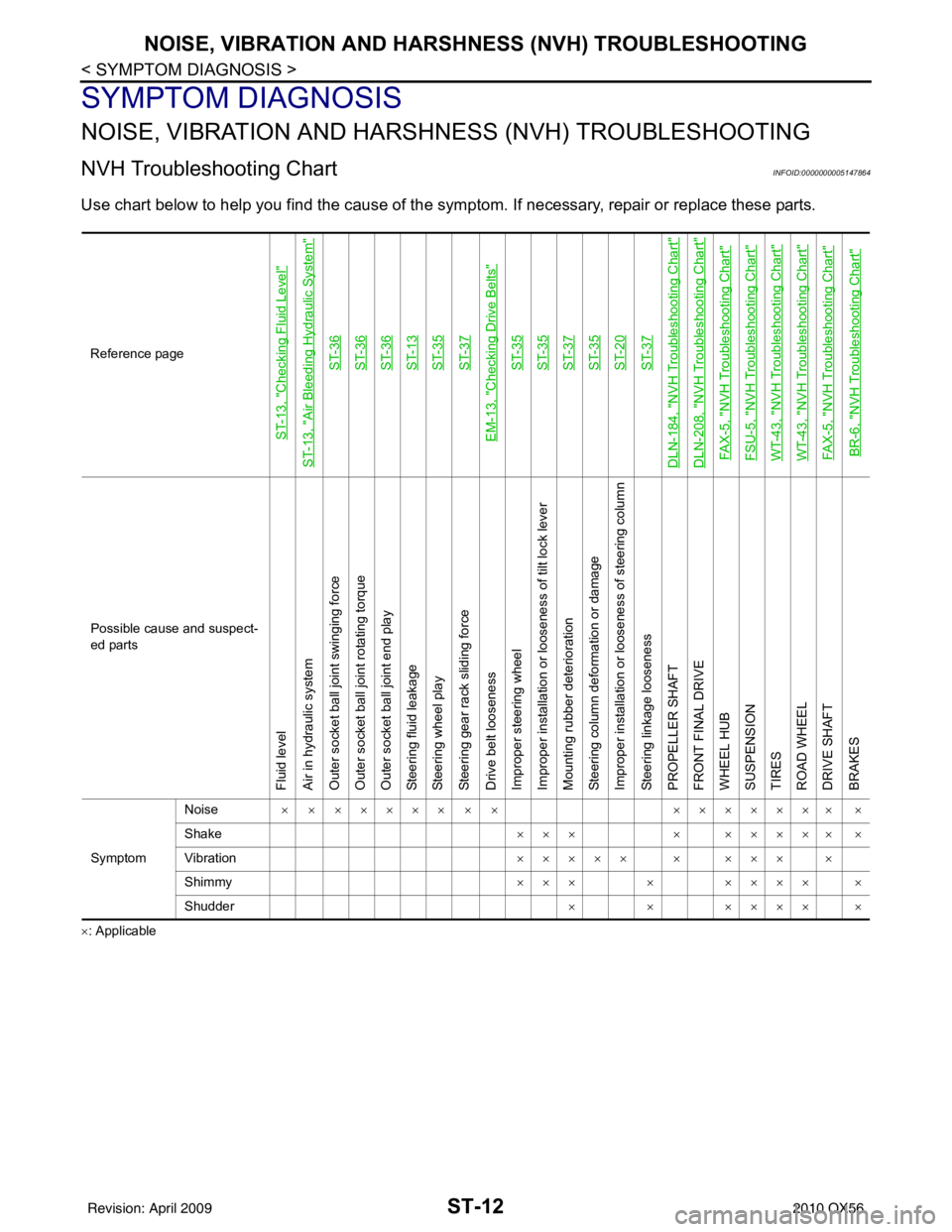
NVH Troubleshooting ChartINFOID:0000000005147864
Use chart below to help you find the cause of the symp tom. If necessary, repair or replace these parts.
×: ApplicableReference page
ST-13, "
Checking Fluid Level
"
ST-13, "
Air Bleeding Hydraulic System
"
ST-36ST-36ST-36ST-13ST-35ST-37
EM-13, "
Checking Drive Belts
"
ST-35ST-35ST-37ST-35ST-20ST-37
DLN-184, "
NVH Troubleshooting Chart
"
DLN-208, "
NVH Troubleshooting Chart
"
FAX-5, "
NVH Troubleshooting Chart
"
FSU-5, "
NVH Troubleshooting Chart
"
WT-43, "
NVH Troubleshooting Chart
"
WT-43, "
NVH Troubleshooting Chart
"
FAX-5, "
NVH Troubleshooting Chart
"
BR-6, "
NVH Troubleshooting Chart
"
Possible cause and suspect-
ed parts
Fluid level
Air in hydraulic system
Outer socket ball joint swinging force
Outer socket ball joint rotating torque
Outer socket ball joint end play
Steering fluid leakage
Steering wheel play
Steering gear rack sliding force
Drive belt looseness
Improper steering wheel
Improper installation or looseness of tilt lock lever
Mounting rubber deterioration
Steering column deformation or damage
Improper installation or looseness of steering column
Steering linkage looseness
PROPELLER SHAFT
FRONT FINAL DRIVE
WHEEL HUB
SUSPENSION
TIRES
ROAD WHEEL
DRIVE SHAFT
BRAKES
Symptom
Noise
× × ××××× × × ××××××× ×
Shake ×××× ××××× ×
Vibration ××××× × ××× ×
Shimmy ××× × ×××× ×
Shudder × × ×××× ×
Revision: April 20092010 QX56
Page 3653 of 4210
STEERING WHEELST-15
< ON-VEHICLE REPAIR >
C
DE
F
H I
J
K L
M A
B
ST
N
O P
ON-VEHICLE REPAIR
STEERING WHEEL
On-Vehicle Inspection and ServiceINFOID:0000000005147868
CHECKING CONDITION OF INSTALLATION
• Check installation condition of steering gear assembly, front suspension, axle and steering column.
• Check if movement exists when steering wheel is mo ved up and down, to the left and right and to the axial
direction.
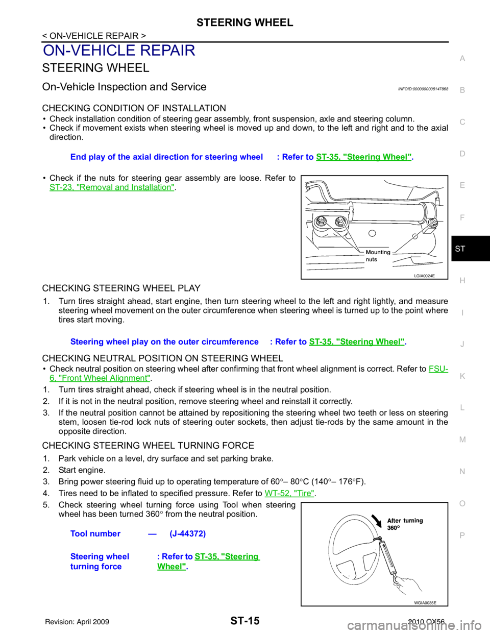
• Check if the nuts for steering gear assembly are loose. Refer to ST-23, "
Removal and Installation".
CHECKING STEERING WHEEL PLAY
1. Turn tires straight ahead, start engine, then turn steer ing wheel to the left and right lightly, and measure
steering wheel movement on the outer circumference when steering wheel is turned up to the point where
tires start moving.
CHECKING NEUTRAL POSITION ON STEERING WHEEL
• Check neutral position on steering wheel after confirming that front wheel alignment is correct. Refer to FSU-
6, "Front Wheel Alignment".
1. Turn tires straight ahead, check if steering wheel is in the neutral position.
2. If it is not in the neutral position, remo ve steering wheel and reinstall it correctly.
3. If the neutral position cannot be attained by repositi oning the steering wheel two teeth or less on steering
stem, loosen tie-rod lock nuts of steering outer socket s, then adjust tie-rods by the same amount in the
opposite direction.
CHECKING STEERING WHEEL TURNING FORCE
1. Park vehicle on a level, dry surface and set parking brake.
2. Start engine.
3. Bring power steering fluid up to operating temperature of 60 °– 80° C (140° – 176°F).
4. Tires need to be inflated to specified pressure. Refer to WT-52, "
Tire".
5. Check steering wheel turning force using Tool when steering wheel has been turned 360 ° from the neutral position.
End play of the axial direction for steering wheel : Refer to
ST-35, "
Steering Wheel".
LGIA0024E
Steering wheel play on the outer circumference : Refer to ST-35, "Steering Wheel".
Tool number — (J-44372)
Steering wheel
turning force : Refer to
ST-35, "
Steering
Wheel".
WGIA0035E
Revision: April 20092010 QX56