2010 INFINITI QX56 brake fluid
[x] Cancel search: brake fluidPage 3698 of 4210
TM-3
CEF
G H
I
J
K L
M A
B
TM
N
O P
Diagnosis Procedure ...........................................
....
80
P1752 INPUT CLUTCH SOLENOID ..................82
Description .......................................................... ....82
CONSULT-III Reference Value in Data Monitor
Mode ................................................................... ....
82
On Board Diagnosis Logic ......................................82
Possible Cause .......................................................82
DTC Confirmation Procedure ..................................82
Diagnosis Procedure ...............................................82
P1757 FRONT BRAKE SOLENOID ...................84
Description .......................................................... ....84
CONSULT-III Reference Value in Data Monitor
Mode ................................................................... ....
84
On Board Diagnosis Logic ......................................84
Possible Cause .......................................................84
DTC Confirmation Procedure ..................................84
Diagnosis Procedure ...............................................84
P1762 DIRECT CLUTCH SOLENOID ................86
Description .......................................................... ....86
CONSULT-III Reference Value in Data Monitor
Mode ................................................................... ....
86
On Board Diagnosis Logic ......................................86
Possible Cause .......................................................86
DTC Confirmation Procedure ..................................86
Diagnosis Procedure ...............................................86
P1767 HIGH AND LOW REVERSE CLUTCH
SOLENOID .........................................................
88
Description .......................................................... ....88
CONSULT-III Reference Value in Data Monitor
Mode ................................................................... ....
88
On Board Diagnosis Logic ......................................88
Possible Cause .......................................................88
DTC Confirmation Procedure ..................................88
Diagnosis Procedure ...............................................88
P1772 LOW COAST BRAKE SOLENOID .........90
Description .......................................................... ....90
CONSULT-III Reference Value in Data Monitor
Mode ................................................................... ....
90
On Board Diagnosis Logic ......................................90
Possible Cause .......................................................90
DTC Confirmation Procedure ..................................90
Diagnosis Procedure ...............................................90
P1774 LOW COAST BRAKE SOLENOID .........92
Description .......................................................... ....92
CONSULT-III Reference Value in Data Monitor
Mode ................................................................... ....
92
On Board Diagnosis Logic ......................................92
Possible Cause .......................................................92
DTC Confirmation Procedure ..................................92
Diagnosis Procedure ...............................................93
MAIN POWER SUPPLY AND GROUND CIR-
CUIT ....................................................................
94
Diagnosis Procedure ........................................... ....94
CLOSED THROTTLE POSITION AND WIDE
OPEN THROTTLE POSITION CIRCUIT ...........
96
CONSULT-III Reference Value in Data Monitor
Mode .................................................................... ....
96
Diagnosis Procedure ...............................................96
BRAKE SIGNAL CIRCUIT ................................97
CONSULT-III Reference Va lue in Data Monitor
Mode .................................................................... ....
97
Diagnosis Procedure ...............................................97
TOW MODE SWITCH .......................................98
Description ...............................................................98
Diagnosis Procedure ...............................................98
A/T SHIFT LOCK SYSTEM ...............................99
Description ...............................................................99
Terminals And Reference Values ............................99
Wiring Diagram - A/T SH IFT LOCK SYSTEM - .....100
Component Inspection ......................................... ..103
ECU DIAGNOSIS .......................................106
TCM .................................................................106
Reference Value .................................................. ..106
Wiring Diagram — A/T CONTROL SYSTEM — .. ..108
Fail-Safe .............................................................. ..117
DTC Inspection Priority Chart ................................119
DTC No. Index .......................................................119
DTC Alphabetical Index .........................................120
SYMPTOM DIAGNOSIS ............................121
SYSTEM SYMPTOM .......................................121
Symptom Table ................................................... ..121
PRECAUTION ............................................143
PRECAUTIONS ...............................................143
Precaution for Supplemental Restraint System
(SRS) "AIR BAG" and "SEAT BELT PRE-TEN-
SIONER" ............................................................. ..
143
Precaution for On Board Diagnosis (OBD) System
of A/T and Engine ................................................ ..
143
Precaution .............................................................143
Service Notice or Precaution .................................144
PREPARATION .........................................146
PREPARATION ...............................................146
Special Service Tool ............................................ ..146
Commercial Service Tool ......................................147
ON-VEHICLE MAINTENANCE ..................148
A/T FLUID .......................................................148
Checking the A/T Fluid (ATF) .............................. ..148
Changing the A/T Fluid (ATF) ................................150
A/T FLUID COOLER .......................................152
A/T Fluid Cooler Cleaning .....................................152
Inspection ..............................................................154
Revision: April 20092010 QX56
Page 3699 of 4210

TM-4
STALL TEST ....................................................155
Inspection and Judgment .................................... ..155
LINE PRESSURE TEST ..................................157
Inspection and Judgment .................................... ..157
ROAD TEST .....................................................159
Description ........................................................... ..159
Check Before Engine Is Started ............................159
Check At Idle ....................................................... ..159
Cruise Test - Part 1 ...............................................160
Cruise Test - Part 2 ...............................................162
Cruise Test - Part 3 ...............................................162
Vehicle Speed When Shifting Gears .....................163
Vehicle Speed When Performing and Releasing
Complete Lock-up .................................................
163
A/T POSITION .................................................164
Adjustment of A/T Position .................................. ..164
Checking of A/T Position .......................................164
ON-VEHICLE REPAIR ...............................165
SHIFT CONTROL SYSTEM ........................... .165
A/T Shift Selector Removal and Installation ..........165
AIR BREATHER HOSE .................................. .166
Removal and Installation ..................................... ..166
OIL PAN ...........................................................170
Oil Pan ................................................................. ..170
CONTROL VALVE WITH TCM ........................172
Control Valve with TCM and A/T Fluid Tempera-
ture Sensor 2 and Plug ........................................ ..
172
REAR OIL SEAL ..............................................184
Rear Oil Seal ....................................................... ..184
FLUID COOLER SYSTEM ...............................185
Exploded View ..................................................... ..185
Removal and Installation .......................................185
REMOVAL AND INSTALLATION ..............186
TRANSMISSION ASSEMBLY ........................ .186
Removal and Installation (2WD) .......................... .186
Removal and Installation (4WD) ...........................188
DISASSEMBLY AND ASSEMBLY ...........192
OVERHAUL ......................................................192
Component .......................................................... .192
Oil Channel ...........................................................199
Location of Adjusting Shims, Needle Bearings,
Thrust Washers and Snap Rings ......................... .
201
DISASSEMBLY .............................................. ..204
Disassembly ......................................................... .204
REPAIR FOR COMPONENT PARTS ..............223
Oil Pump .............................................................. .223
Front Sun Gear, 3rd One-Way Clutch ...................225
Front Carrier, Input Clutch, Rear Internal Gear .....227
Mid Sun Gear, Rear Sun Gear, High and Low Re-
verse Clutch Hub ................................................. .
232
High and Low Reverse Clutch ..............................237
Direct Clutch .........................................................239
ASSEMBLY .................................................... ..242
Assembly (1) ........................................................ .242
Adjustment ............................................................255
Assembly (2) .........................................................257
SERVICE DATA AND SPECIFICATIONS
(SDS) ........ .................................................
265
SERVICE DATA AND SPECIFICATIONS
(SDS) .............................................................. ..
265
General Specification ........................................... .265
Vehicle Speed at Which Gear Shifting Occurs .....265
Vehicle Speed at Which Lock-up Occurs/Releas-
es ......................................................................... .
266
Stall Speed ............................................................266
Line Pressure ........................................................266
Input Speed Sensor ..............................................266
Output Speed Sensor ...........................................266
Reverse Brake ......................................................266
Total End Play .......................................................267
Torque Converter ..................................................267
Revision: April 20092010 QX56
Page 3702 of 4210
DIAGNOSIS AND REPAIR WORKFLOWTM-7
< BASIC INSPECTION >
CEF
G H
I
J
K L
M A
B
TM
N
O P
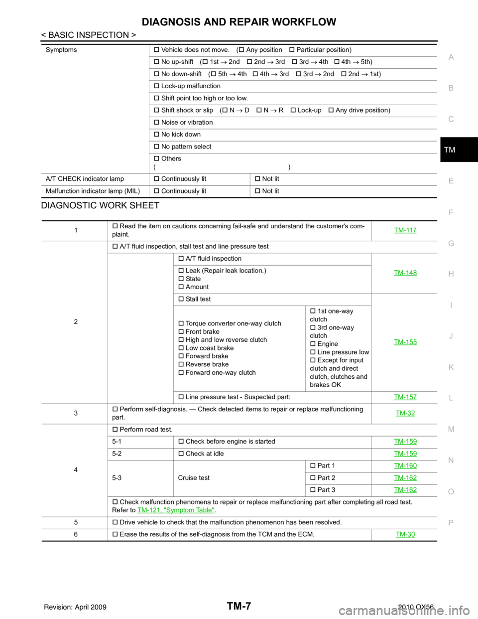
DIAGNOSTIC WORK SHEET
Symptoms �† Vehicle does not move. ( �† Any position �† Particular position)
�† No up-shift ( �† 1st → 2nd �† 2nd → 3rd �† 3rd → 4th �† 4th → 5th)
�† No down-shift ( �† 5th → 4th �† 4th → 3rd �† 3rd → 2nd �† 2nd → 1st)
�† Lock-up malfunction
�† Shift point too high or too low.
�† Shift shock or slip ( �† N → D �† N → R �† Lock-up �† Any drive position)
�† Noise or vibration
�† No kick down
�† No pattern select
�† Others
()
A/T CHECK indicator lamp �† Continuously lit �† Not lit
Malfunction indicator lamp (MIL) �† Continuously lit �† Not lit
1 �†
Read the item on cautions concerning fail-safe and understand the customer's com-
plaint. TM-117
2�†
A/T fluid inspection, stall test and line pressure test
�† A/T fluid inspection
TM-148
�† Leak (Repair leak location.)
�† Sta te
�† Amount
�† Stall test
TM-155
�† Torque converter one-way clutch
�† Front brake
�† High and low reverse clutch
�† Low coast brake
�† Forward brake
�† Reverse brake
�† Forward one-way clutch �†
1st one-way
clutch
�† 3rd one-way
clutch
�† Engine
�† Line pressure low
�† Except for input
clutch and direct
clutch, clutches and
brakes OK
�† Line pressure test - Suspected part: TM-157
3�†
Perform self-diagnosis. — Check detected items to repair or replace malfunctioning
part. TM-32
4�†
Perform road test.
5-1 �† Check before engine is started TM-159
5-2�† Check at idle TM-159
5-3Cruise test �†
Part 1 TM-160�† Part 2 TM-162
�† Part 3 TM-162
�† Check malfunction phenomena to repair or replace malfunctioning part after completing all road test.
Refer to TM-121, "
Symptom Table".
5 �† Drive vehicle to check that the malfunction phenomenon has been resolved.
6 �† Erase the results of the self-diagnosis from the TCM and the ECM. TM-30
Revision: April 20092010 QX56
Page 3716 of 4210
A/T CONTROL SYSTEMTM-21
< FUNCTION DIAGNOSIS >
CEF
G H
I
J
K L
M A
B
TM
N
O P
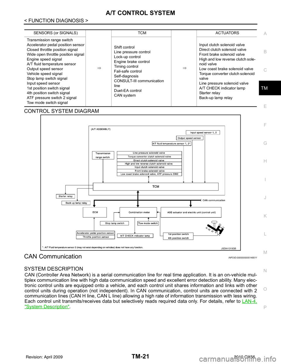
CONTROL SYSTEM DIAGRAM
CAN CommunicationINFOID:0000000005148511
SYSTEM DESCRIPTION
CAN (Controller Area Network) is a serial communication line for real time application. It is an on-vehicle mul-
tiplex communication line with high data communication speed and excellent error detection ability. Many elec-
tronic control units are equipped onto a vehicle, and each control unit shares information and links with other
control units during operation (not independent). In CAN communication, control units are connected with 2
communication lines (CAN H line, CAN L line) allowing a high rate of information transmission with less wiring.
Each control unit transmits/receives data but selectively reads required data only. For details, refer to LAN-4,
"System Description".
SENSORS (or SIGNALS)
⇒TCM
⇒ACTUATORS
Transmission range switch
Accelerator pedal position sensor
Closed throttle position signal
Wide open throttle position signal
Engine speed signal
A/T fluid temperature sensor
Output speed sensor
Vehicle speed signal
Stop lamp switch signal
Input speed sensor
1st position switch signal
4th position switch signal
ATF pressure switch 2 signal
Tow mode switch signal Shift control
Line pressure control
Lock-up control
Engine brake control
Timing control
Fail-safe control
Self-diagnosis
CONSULT-III co
mmunication
line
Duet-EA control
CAN system Input clutch solenoid valve
Direct clutch solenoid valve
Front brake solenoid valve
High and low reverse clutch sole-
noid valve
Low coast brake solenoid valve
Torque converter clutch solenoid
valve
Line pressure solenoid valve
A/T CHECK indicator lamp
Starter relay
Back-up lamp relay
JSDIA1315GB
Revision: April 20092010 QX56
Page 3717 of 4210

TM-22
< FUNCTION DIAGNOSIS >
A/T CONTROL SYSTEM
Input/Output Signal of TCM
INFOID:0000000005148512
*1: Spare for output speed sensor
*2: Spare for accelerator pedal position signal
*3: If these input and output signals are different, the TCM triggers the fail-safe function.
*4: CAN comm unications
*5: Used as a condition for starting self-diagnostics; if self-diagnostics are not started, it is judged that there is some kin d of error.
*6: A/T fluid temperature sensor 2 does not have any function.
Line Pressure ControlINFOID:0000000005148513
• When an input torque signal equivalent to the engine drive force is sent from the ECM to the TCM, the TCM
controls the line pressure solenoid.
Control item Line
pres- sure
control Vehicle
speed
control S h i f t
control Lock-up
control Engine
brake
control Fail-safe
function (*3) Self-diag-
nostics
function
Input Accelerator pedal position signal
(*4)XXXXX X X
Output speed sensor X X X X X X
Vehicle speed signal
(*1) (*4)XXXX X
Closed throttle position signal
(*4)(*2) X (*2) X X (*2) X(*5) X
Wide open throttle position signal
(*4)(*2) X (*2) X (*2) X(*5) X
Input speed sensor 1 X XXX X
Input speed sensor 2
(for 4th speed only) XX X
X X
Engine speed signals
(*4)XX
Transmission range switch X X X X X X X
Stop lamp switch signal
(*4)XXX (*5) X
A/T fluid temperature sensors 1, 2 (*6) X X X X X X X
ASCD Operation signal
(*4)XXXX
Overdrive cancel sig-
nal
(*4)XXX
TCM power supply voltage signal X X X X X X
Output Direct clutch solenoid
X XX X
Input clutch solenoid X XX X
High and low reverse clutch solenoid X XX X
Front brake solenoid X XX X
Low coast brake solenoid (ATF pressure
switch 2) XX X X X
Line pressure solenoid X X X X X X X
TCC solenoid XX X
Starter relay XX
Revision: April 20092010 QX56
Page 3719 of 4210
TM-24
< FUNCTION DIAGNOSIS >
A/T CONTROL SYSTEM
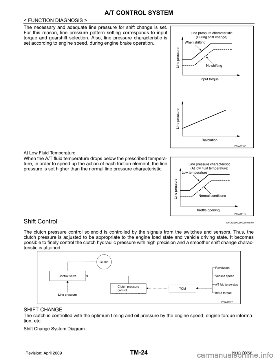
The necessary and adequate line pressure for shift change is set.
For this reason, line pressure pattern setting corresponds to input
torque and gearshift selection. Also, line pressure characteristic is
set according to engine speed, during engine brake operation.
At Low Fluid Temperature
When the A/T fluid temperature drops below the prescribed tempera-
ture, in order to speed up the action of each friction element, the line
pressure is set higher than the normal line pressure characteristic.
Shift ControlINFOID:0000000005148514
The clutch pressure control solenoid is controlled by the signals from the switches and sensors. Thus, the
clutch pressure is adjusted to be appropriate to the engine load state and vehicle driving state. It becomes
possible to finely control the clutch hydraulic pressure with high precision and a smoother shift change charac-
teristic is attained.
SHIFT CHANGE
The clutch is controlled with the optimum timing and oil pressure by the engine speed, engine torque informa-
tion, etc.
Shift Change System Diagram
PCIA0010E
PCIA0011E
PCIA0012E
Revision: April 20092010 QX56
Page 3728 of 4210

DIAGNOSIS SYSTEM (TCM)TM-33
< FUNCTION DIAGNOSIS >
CEF
G H
I
J
K L
M A
B
TM
N
O P
4GR INCORRECT RA-
TIO • A/T cannot shift to 4GR.
P0734 P0734TM-62
5GR INCORRECT RA-
TIO• A/T cannot shift to 5GR.
P0735 P0735TM-64
TORQUE CONVERT-
ER• Normal voltage not applied to solenoid due to cut line,
short, or the like. P0740 P0740
TM-65
TORQUE CONVERT-
ER• A/T cannot perform lock-up even if electrical circuit is
good.
• TCM detects as irregular by comparing difference val-
ue with slip rotation. P0744 P0744*2
TM-68
PC SOLENOID A• Normal voltage not applied to solenoid due to cut line,
short, or the like.
• TCM detects as irregular by comparing target value
with monitor value. P0745 P0745
TM-69
TP SENSOR• TCM does not receive the proper accelerator pedal po-
sition signals (input by CAN communication) from
ECM. P1705 P1705
TM-71
FLUID TEMP SENSOR• During running, the ATF temperature sensor signal
voltage is excessively high or low. P1710 P0710
TM-73
VEHICLE SPEED SIG-
NAL• Signal (CAN communication) from vehicle speed sig-
nal not input due to cut line or the like.
• Unexpected signal input during running. P1721
—TM-76
INTERLOCK • Except during shift change, the gear position and ATF
pressure switch states are monitored and comparative
judgement made. P1730 P1730
TM-78
1GR E/BRAKING• Each ATF pressure switch and solenoid current is
monitored and if a pattern is detected having engine
braking 1GR other than in the "1" position, a malfunc-
tion is detected. P1731
—TM-80
INPUT CLUTCH SOLE-
NOID • Normal voltage not applied to solenoid due to function-
al malfunction, cut line, short, or the like.
• TCM detects as irregular by comparing target value
with monitor value. P1752 P1752
TM-82
FR BRAKE SOLENOID• Normal voltage not applied to solenoid due to function-
al malfunction, cut line, short, or the like.
• TCM detects as irregular by comparing target value
with monitor value. P1757 P1757
TM-84
DRCT CLUTCH SOLE-
NOID• Normal voltage not applied to solenoid due to cut line,
short, or the like.
• TCM detects as irregular by comparing target value
with monitor value. P1762 P1762
TM-86
HLR CLUTCH SOLE-
NOID• Normal voltage not applied to solenoid due to function-
al malfunction, cut line, short, or the like.
• TCM detects as irregular by comparing target value
with monitor value. P1767 P1767
TM-88
L C BRAKE SOLENOID• Normal voltage not applied to solenoid due to function-
al malfunction, cut line, short, or the like. P1772 P1772
TM-90
Items (CONSULT-III
screen terms) Malfunction is detected when... TCM self-di-
agnosis OBD (DTC)
Reference
“TRANSMIS-
SION” with
CONSULT-III MIL indicator
lamp*1, “EN-
GINE” with
CONSULT-III or
GST
Revision: April 20092010 QX56
Page 3734 of 4210
DIAGNOSIS SYSTEM (TCM)TM-39
< FUNCTION DIAGNOSIS >
CEF
G H
I
J
K L
M A
B
TM
N
O P
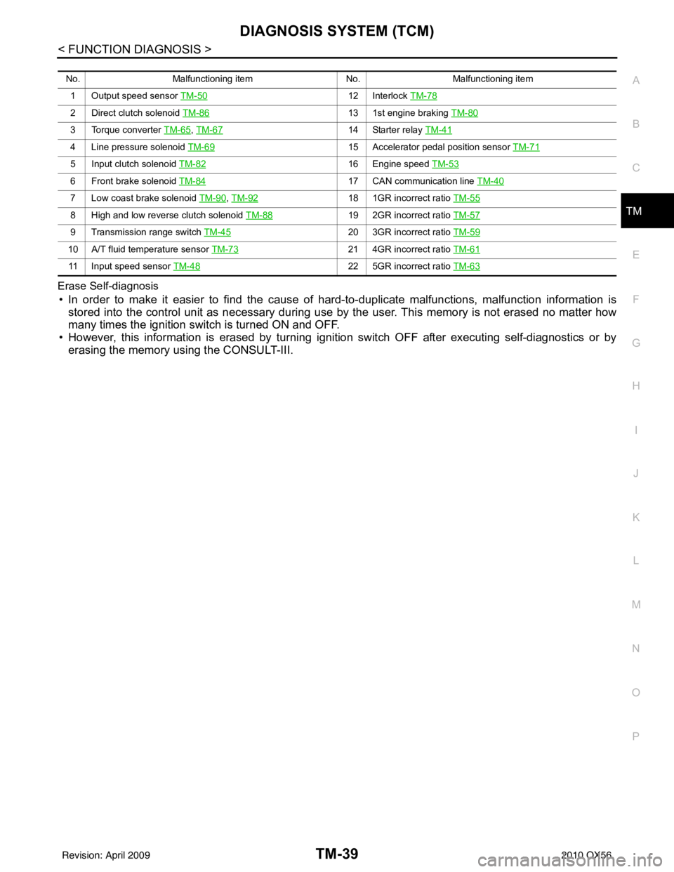
Erase Self-diagnosis
• In order to make it easier to find the cause of
hard-to-duplicate malfunctions, malfunction information is
stored into the control unit as necessary during use by the user. This memory is not erased no matter how
many times the ignition switch is turned ON and OFF.
• However, this information is erased by turning ignition switch OFF after executing self-diagnostics or by erasing the memory using the CONSULT-III.
No. Malfunctioning item No.Malfunctioning item
1 Output speed sensor TM-50
12 Interlock TM-78
2 Direct clutch solenoid TM-8613 1st engine braking TM-80
3 Torque converter TM-65, TM-6714 Starter relay TM-41
4 Line pressure solenoid TM-6915 Accelerator pedal position sensor TM-71
5 Input clutch solenoid TM-8216 Engine speed TM-53
6 Front brake solenoid TM-8417 CAN communication line TM-40
7 Low coast brake solenoid TM-90, TM-9218 1GR incorrect ratio TM-55
8 High and low reverse clutch solenoid TM-8819 2GR incorrect ratio TM-57
9 Transmission range switch TM-4520 3GR incorrect ratio TM-59
10 A/T fluid temperature sensor TM-7321 4GR incorrect ratio TM-61
11 Input speed sensor TM-4822 5GR incorrect ratio TM-63
Revision: April 20092010 QX56