Page 3834 of 4210
SYSTEM SYMPTOMTM-139
< SYMPTOM DIAGNOSIS >
CEF
G H
I
J
K L
M A
B
TM
N
O P
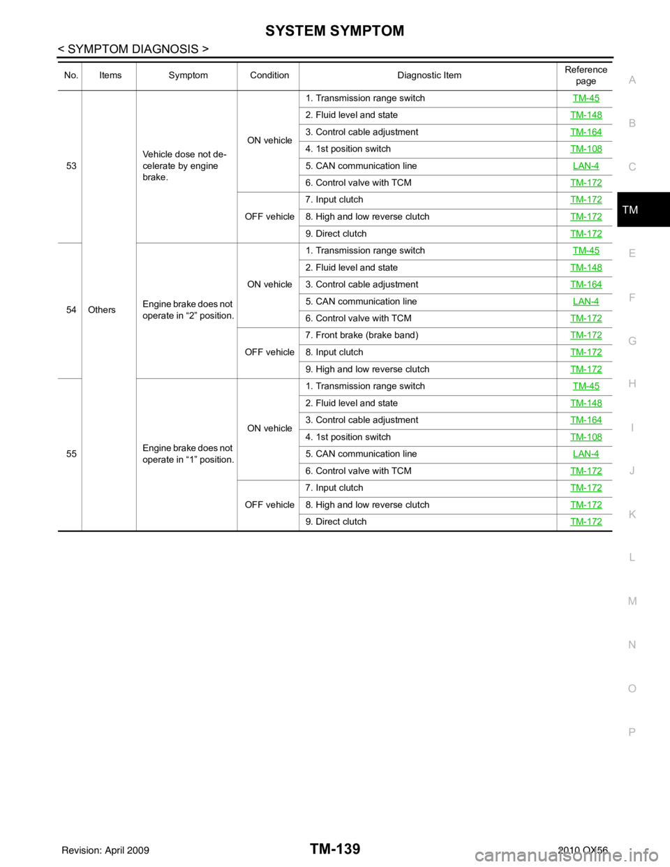
53
Others Vehicle dose not de-
celerate by engine
brake.
ON vehicle1. Transmission range switch
TM-45
2. Fluid level and stateTM-148
3. Control cable adjustmentTM-164
4. 1st position switchTM-108
5. CAN communication line LAN-4
6. Control valve with TCMTM-172
OFF vehicle7. Input clutch
TM-1728. High and low reverse clutchTM-172
9. Direct clutchTM-172
54Engine brake does not
operate in “2” position. ON vehicle1. Transmission range switch
TM-45
2. Fluid level and stateTM-148
3. Control cable adjustmentTM-164
5. CAN communication line LAN-4
6. Control valve with TCMTM-172
OFF vehicle7. Front brake (brake band)
TM-1728. Input clutchTM-172
9. High and low reverse clutchTM-172
55Engine brake does not
operate in “1” position. ON vehicle1. Transmission range switch
TM-45
2. Fluid level and stateTM-148
3. Control cable adjustmentTM-164
4. 1st position switchTM-108
5. CAN communication line LAN-4
6. Control valve with TCMTM-172
OFF vehicle7. Input clutch
TM-1728. High and low reverse clutchTM-172
9. Direct clutchTM-172
No. ItemsSymptom Condition Diagnostic ItemReference
page
Revision: April 20092010 QX56
Page 3835 of 4210
TM-140
< SYMPTOM DIAGNOSIS >
SYSTEM SYMPTOM
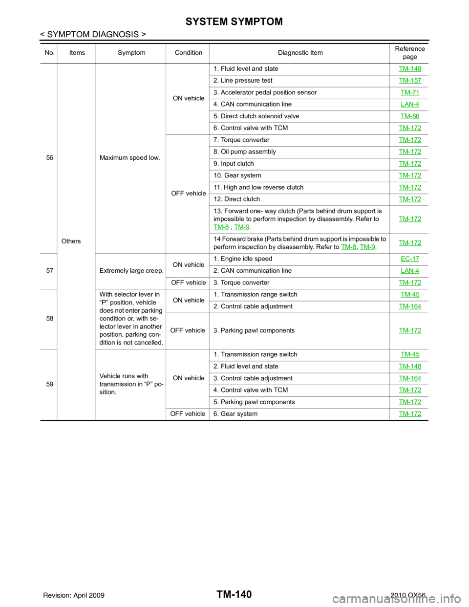
56Others Maximum speed low.
ON vehicle
1. Fluid level and state
TM-148
2. Line pressure testTM-157
3. Accelerator pedal position sensor TM-71
4. CAN communication line LAN-4
5. Direct clutch solenoid valveTM-86
6. Control valve with TCMTM-172
OFF vehicle7. Torque converter
TM-172
8. Oil pump assemblyTM-172
9. Input clutchTM-172
10. Gear systemTM-172
11. High and low reverse clutchTM-172
12. Direct clutchTM-172
13. Forward one- way clutch (Parts behind drum support is
impossible to perform inspection by disassembly. Refer to
TM-8
, TM-9. TM-172
14 Forward brake (Parts behind drum support is impossible to
perform inspection by disassembly. Refer to TM-8
,
TM-9. TM-172
57
Extremely large creep. ON vehicle1. Engine idle speed
EC-172. CAN communication lineLAN-4
OFF vehicle 3. Torque converter TM-172
58With selector lever in
“P” position, vehicle
does not enter parking
condition or, with se-
lector lever in another
position, parking con-
dition is not cancelled. ON vehicle
1. Transmission range switch
TM-45
2. Control cable adjustmentTM-164
OFF vehicle 3. Parking pawl components TM-172
59Vehicle runs with
transmission in “P” po-
sition. ON vehicle1. Transmission range switch
TM-45
2. Fluid level and stateTM-148
3. Control cable adjustmentTM-164
4. Control valve with TCMTM-172
5. Parking pawl componentsTM-172
OFF vehicle 6. Gear system TM-172
No. ItemsSymptom Condition Diagnostic ItemReference
page
Revision: April 20092010 QX56
Page 3836 of 4210
SYSTEM SYMPTOMTM-141
< SYMPTOM DIAGNOSIS >
CEF
G H
I
J
K L
M A
B
TM
N
O P
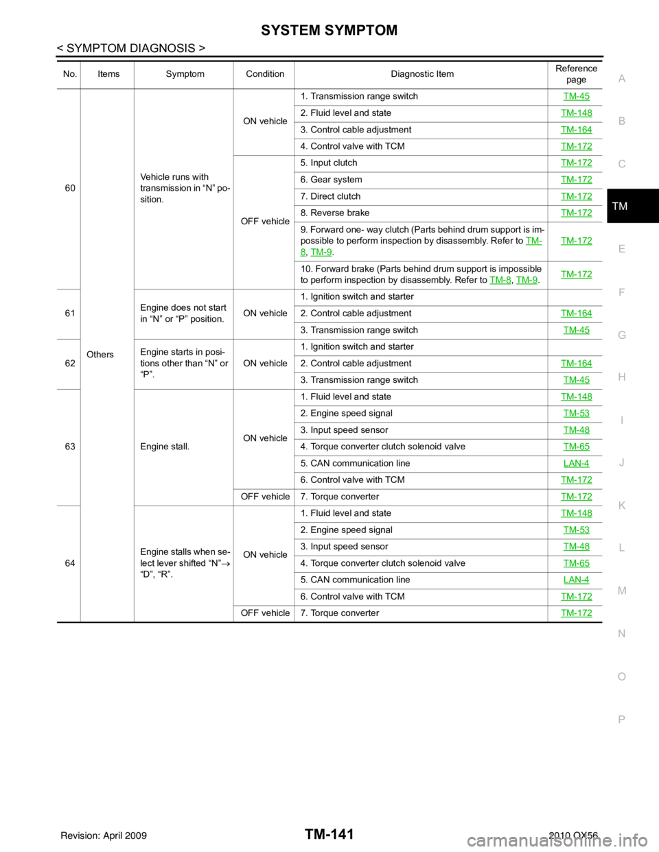
60
Others Vehicle runs with
transmission in “N” po-
sition.
ON vehicle
1. Transmission range switch
TM-45
2. Fluid level and stateTM-148
3. Control cable adjustmentTM-164
4. Control valve with TCMTM-172
OFF vehicle5. Input clutch
TM-172
6. Gear systemTM-172
7. Direct clutchTM-172
8. Reverse brakeTM-172
9. Forward one- way clutch (Parts behind drum support is im-
possible to perform inspection by disassembly. Refer to TM-
8, TM-9. TM-172
10. Forward brake (Parts behind drum support is impossible
to perform inspection by disassembly. Refer to
TM-8
, TM-9. TM-172
61 Engine does not start
in “N” or “P” position. ON vehicle1. Ignition switch and starter
2. Control cable adjustment
TM-164
3. Transmission range switch TM-45
62Engine starts in posi-
tions other than “N” or
“P”. ON vehicle1. Ignition switch and starter
2. Control cable adjustment
TM-164
3. Transmission range switch TM-45
63Engine stall. ON vehicle1. Fluid level and state
TM-148
2. Engine speed signal TM-53
3. Input speed sensorTM-48
4. Torque converter clutch solenoid valveTM-65
5. CAN communication line LAN-4
6. Control valve with TCMTM-172
OFF vehicle 7. Torque converter TM-172
64Engine stalls when se-
lect lever shifted “N”
→
“D”, “R”. ON vehicle1. Fluid level and state
TM-148
2. Engine speed signal TM-53
3. Input speed sensorTM-48
4. Torque converter clutch solenoid valveTM-65
5. CAN communication line LAN-4
6. Control valve with TCMTM-172
OFF vehicle 7. Torque converter TM-172
No. ItemsSymptom Condition Diagnostic ItemReference
page
Revision: April 20092010 QX56
Page 3837 of 4210
TM-142
< SYMPTOM DIAGNOSIS >
SYSTEM SYMPTOM
65Others Engine speed does
not return to idle.
ON vehicle1. Fluid level and state
TM-148
2. Direct clutch solenoid valve TM-86
3. Front brake solenoid valveTM-84
4. Accelerator pedal position sensorTM-71
5. Output speed sensor and vehicle speed signalTM-50,
TM-76
6. CAN communication line LAN-4
7. Control valve with TCMTM-172
OFF vehicle8. Front brake (brake band)
TM-1729. Direct clutchTM-172
66A/T CHECK indicator
lamp does not come
on. ON vehicle1. CAN communication line
LAN-42. Combination meterMWI-22
3. TCM power supply TM-94
No. ItemsSymptom Condition Diagnostic ItemReference
page
Revision: April 20092010 QX56
Page 3843 of 4210
TM-148
< ON-VEHICLE MAINTENANCE >
A/T FLUID
ON-VEHICLE MAINTENANCE
A/T FLUID
Checking the A/T Fluid (ATF)INFOID:0000000005148722
CAUTION:
If using the vehicle for towing, the A/T fluid must be replaced as specified. Refer to MA-9, "
Introduc-
tion of Periodic Maintenance".
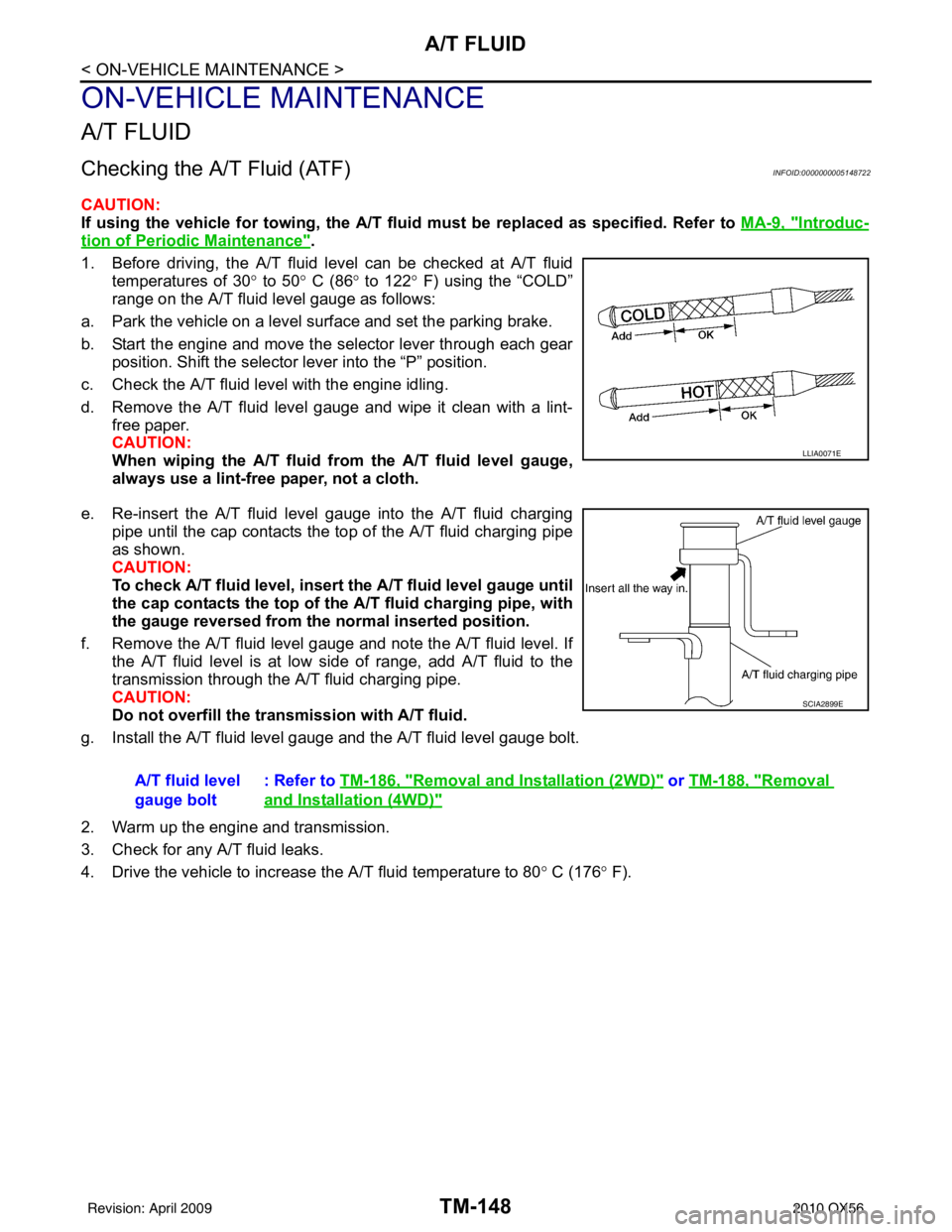
1. Before driving, the A/T fluid level can be checked at A/T fluid temperatures of 30 ° to 50° C (86° to 122° F) using the “COLD”
range on the A/T fluid level gauge as follows:
a. Park the vehicle on a level surface and set the parking brake.
b. Start the engine and move the selector lever through each gear position. Shift the selector lever into the “P” position.
c. Check the A/T fluid level with the engine idling.
d. Remove the A/T fluid level gauge and wipe it clean with a lint- free paper.
CAUTION:
When wiping the A/T fluid from the A/ T fluid level gauge,
always use a lint-free paper, not a cloth.
e. Re-insert the A/T fluid level gauge into the A/T fluid charging pipe until the cap contacts the t op of the A/T fluid charging pipe
as shown.
CAUTION:
To check A/T fluid level, insert th e A/T fluid level gauge until
the cap contacts the top of the A/T fluid charging pipe, with
the gauge reversed from th e normal inserted position.
f. Remove the A/T fluid level gauge and note the A/T fluid level. If the A/T fluid level is at low si de of range, add A/T fluid to the
transmission through the A/T fluid charging pipe.
CAUTION:
Do not overfill the transmission with A/T fluid.
g. Install the A/T fluid level gauge and the A/T fluid level gauge bolt.
2. Warm up the engine and transmission.
3. Check for any A/T fluid leaks.
4. Drive the vehicle to increase the A/T fluid temperature to 80 ° C (176 ° F).
LLIA0071E
A/T fluid level
gauge bolt : Refer to
TM-186, "Removal and Installation (2WD)" or TM-188, "Removal
and Installation (4WD)"
SCIA2899E
Revision: April 20092010 QX56
Page 3850 of 4210
STALL TESTTM-155
< ON-VEHICLE MAINTENANCE >
CEF
G H
I
J
K L
M A
B
TM
N
O P
STALL TEST
Inspection and JudgmentINFOID:0000000005148726
A/T FLUID CHECK
Fluid Leakage and Fluid Level Check
• Inspect for fluid leakage and check the fluid level. Refer to TM-148, "Checking the A/T Fluid (ATF)".
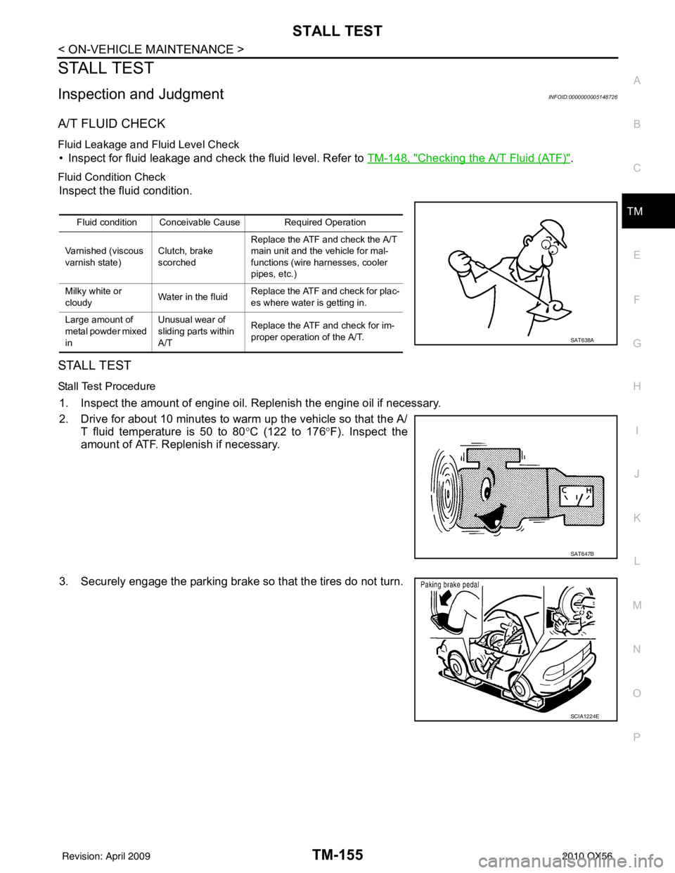
Fluid Condition Check
Inspect the fluid condition.
STALL TEST
Stall Test Procedure
1. Inspect the amount of engine oil. Replenish the engine oil if necessary.
2. Drive for about 10 minutes to warm up the vehicle so that the A/
T fluid temperature is 50 to 80 °C (122 to 176 °F). Inspect the
amount of ATF. Replenish if necessary.
3. Securely engage the parking brake so that the tires do not turn.
Fluid condition Conceivable Cause Required Operation
Varnished (viscous
varnish state) Clutch, brake
scorchedReplace the ATF and check the A/T
main unit and the vehicle for mal-
functions (wire harnesses, cooler
pipes, etc.)
Milky white or
cloudy Water in the fluidReplace the ATF and check for plac-
es where water is getting in.
Large amount of
metal powder mixed
in Unusual wear of
sliding parts within
A/T
Replace the ATF and check for im-
proper operation of the A/T.
SAT638A
SAT647B
SCIA1224E
Revision: April 20092010 QX56
Page 3852 of 4210
LINE PRESSURE TESTTM-157
< ON-VEHICLE MAINTENANCE >
CEF
G H
I
J
K L
M A
B
TM
N
O P
LINE PRESSURE TEST
Inspection and JudgmentINFOID:0000000005148727
LINE PRESSURE TEST
Line Pressure Test Port
Line Pressure Test Procedure
1. Inspect the amount of engine oil and replenish if necessary.
2. Drive the car for about 10 minutes to warm it up so that the ATF reaches in range of 50 to 80 °C (122 to
176° F), then inspect the amount of ATF and replenish if necessary.
NOTE:
The automatic fluid temperature rises in range of 50 to 80 °C (122 to 176° F) during 10 minutes of
driving.
3. After warming up remove the oil pressure detection plug and install the Tool.
CAUTION:
When using the oil pressure ga uge, be sure to use the O-
ring attached to the oil pressure detection plug.
4. Securely engage the parking brake so that the tires do not turn.
SCIA2187E
SCIA5309E
SCIA1224E
Revision: April 20092010 QX56
Page 4012 of 4210

WCS
DIAGNOSIS SYSTEM (METER)WCS-13
< FUNCTION DIAGNOSIS >
C
DE
F
G H
I
J
K L
M B A
O P
NOTE:
Some items are not available due to vehicle specification.
*: The monitor will indicate “OFF” even though the brake warnin g lamp is on if either of the following conditions exist.
• The parking brake is engaged
• The brake fluid level is low AT SFT DWN SW [ON/OFF]
XX Displays [ON/O FF] condition of A/T shift-down switch.
DISTANCE [km] or [mile] XXDisplays the value, which is calculated by vehicle speed signal, fuel
gauge and fuel consumption from ECM.
BUZZER [ON/OFF] XX Displays [ON/ OFF] condition of buzzer.
BRAKE SW [ON/OFF] X Indicates [ON/OFF] condition of parking brake switch.
AT-M GEAR [1, 2, 3, 4] XX Indicates [1, 2, 3, 4] condition of A/T manual mode gear position.
P RANGE IND [ON/OFF] XX Indicates [ON/OFF] condition of A/T shift P range indicator.
R RANGE IND [ON/OFF] XX Indicates [ON/OFF] condition of A/T shift R range indicator.
N RANGE IND [ON/OFF] XX Indicates [ON/OFF] condition of A/T shift N range indicator.
D RANGE IND [ON/OFF] XX Indicates [ON/OFF] condition of A/T shift D range indicator.
4 RANGE IND [ON/OFF] XX Indicates [ON/OFF] condition of A/T shift 4 range indicator.
3 RANGE IND [ON/OFF] XX Indicates [ON/OFF] condition of A/T shift 3 range indicator.
2 RANGE IND [ON/OFF] XX Indicates [ON/OFF] condition of A/T shift 2 range indicator.
1 RANGE IND [ON/OFF] XX Indicates [ON/OFF] condition of A/T shift 1range indicator.
CRUISE W/L [ON/OFF] X Indicates [ON/OFF] condition of CRUISE warning lamp.
4WD LOCK SW [ON/OFF] X Indicates [ON/OFF] condition of 4WD lock switch.
4WD LOCK IND [ON/OFF] X Indicates [ON/OFF] condition of 4WD lock indicator.
SEAT BELT W/L [ON/OFF] X Indicates [ON/OFF] condition of seat belt warning lamp.
LIGHT IND [ON/OFF] X Indicates [ON/OFF] condition of light indicator.
4WD W/L [ON/OFF] X Indicates [ON/OFF] condition of 4WD warning lamp.
Display item [Unit]
MAIN
SIGNALS SELECTION
FROM MENU Description
Revision: April 20092010 QX56