2010 INFINITI QX56 Ignition switch
[x] Cancel search: Ignition switchPage 2477 of 4210

INL-8
< FUNCTION DIAGNOSIS >
INTERIOR ROOM LAMP CONTROL SYSTEM
Component Description
INFOID:0000000005146718
13. Rear step lamp LH D206 Rear step lamp RH D306 14. Cargo lamp B153 15. Personal lamp 3rd row R205
16. Personal lamp 2nd row R203
Part name Description
BCM Provides power and ground and controls timer functions for the
interior room lamps, step lamps and cargo lamp.
Key switch and ignition knob switch Provides key in ignition status to the BCM.
Door switches Provides door OPEN/CLOSED status to the BCM.
Glass hatch switch Provides glass hatch OPEN/CLOSED status to the BCM.
Back door latch Provides back door OPEN/CLOSED status to the BCM.
Power window and door lock/unlock switch RH Provides door lock/unlock position switch RH status to the BCM.
Main power window and door lock/unlock switch [front door lock
assembly LH (key cylinder switch)]. Provides door lock/unlock position switch LH status to the BCM.
Revision: April 20092010 QX56
Page 2478 of 4210
ILLUMINATION CONTROL SYSTEMINL-9
< FUNCTION DIAGNOSIS >
C
DE
F
G H
I
J
K
M A
B
INL
N
O P
ILLUMINATION CONTROL SYSTEM
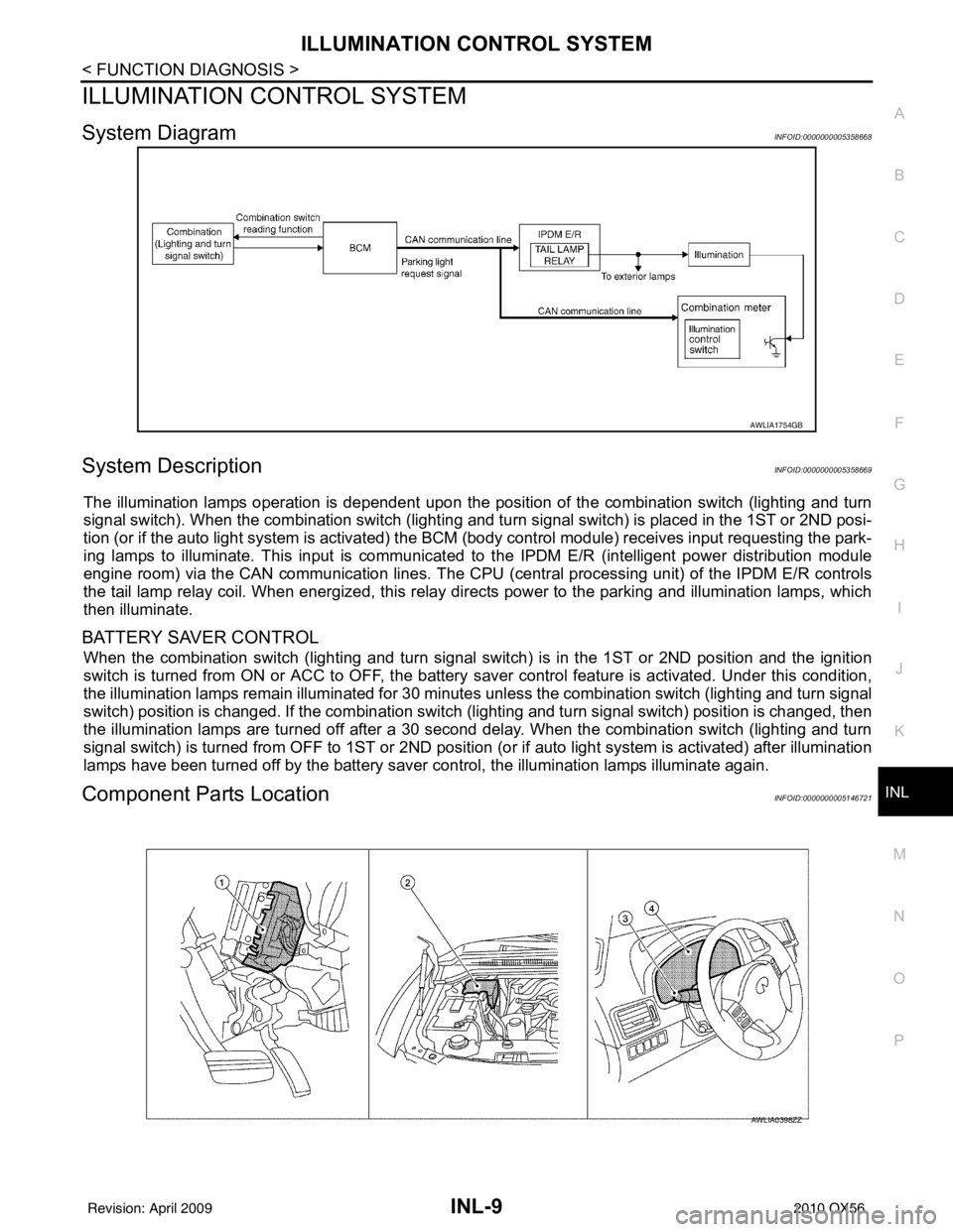
System DiagramINFOID:0000000005358668
System DescriptionINFOID:0000000005358669
The illumination lamps operation is dependent upon the posit ion of the combination switch (lighting and turn
signal switch). When the combination switch (lighting and turn signal switch) is placed in the 1ST or 2ND posi-
tion (or if the auto light system is activated) the BCM (body control modul e) receives input requesting the park-
ing lamps to illuminate. This input is communicated to the IPDM E/R (intelligent power distribution module
engine room) via the CAN communication lines. The CPU (central processing unit) of the IPDM E/R controls
the tail lamp relay coil. When energized, this relay directs power to the parking and illumination lamps, which
then illuminate.
BATTERY SAVER CONTROL
When the combination switch (lighting and turn signal s witch) is in the 1ST or 2ND position and the ignition
switch is turned from ON or ACC to OFF, the battery saver control feature is activated. Under this condition,
the illumination lamps remain illuminated for 30 minutes unless the combination switch (lighting and turn signal
switch) position is changed. If the combination switch (lighting and turn signal switch) position is changed, then
the illumination lamps are turned off after a 30 second delay. When the combination switch (lighting and turn
signal switch) is turned from OFF to 1ST or 2ND position (or if auto light system is activated) after illumination
lamps have been turned off by the battery saver c ontrol, the illumination lamps illuminate again.
Component Parts LocationINFOID:0000000005146721
AWLIA1754GB
AWLIA0398ZZ
Revision: April 20092010 QX56
Page 2481 of 4210
INL-12
< FUNCTION DIAGNOSIS >
DIAGNOSIS SYSTEM (BCM)
INT LAMP : CONSULT-III Fu nction (BCM - INT LAMP)
INFOID:0000000005356687
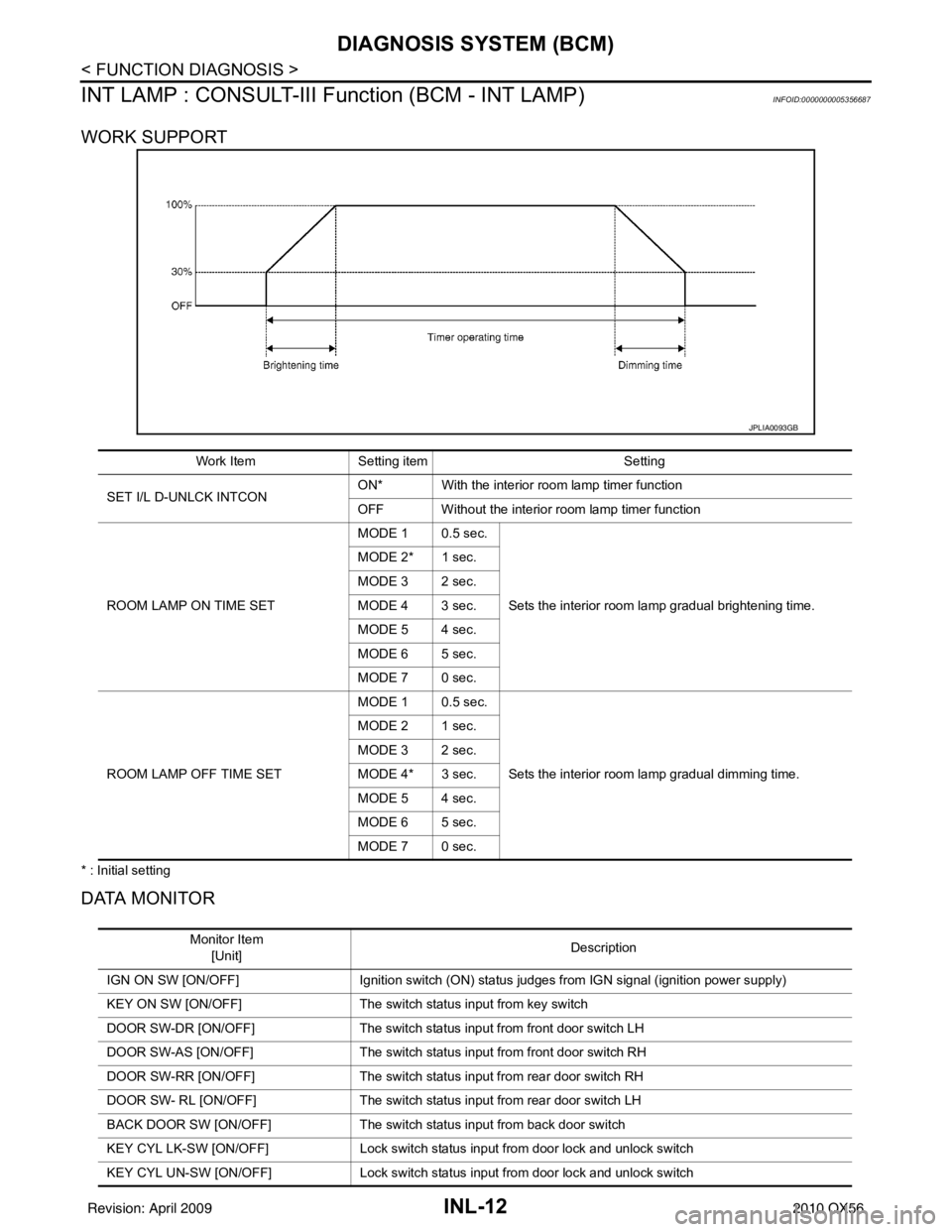
WORK SUPPORT
* : Initial setting
DATA MONITOR
JPLIA0093GB
Work ItemSetting item Setting
SET I/L D-UNLCK INTCON ON* With the interior room lamp timer function
OFF Without the interior room lamp timer function
ROOM LAMP ON TIME SET MODE 1 0.5 sec.
Sets the interior room lamp gradual brightening time.
MODE 2* 1 sec.
MODE 3 2 sec.
MODE 4 3 sec.
MODE 5 4 sec.
MODE 6 5 sec.
MODE 7 0 sec.
ROOM LAMP OFF TIME SET MODE 1 0.5 sec.
Sets the interior room lamp gradual dimming time.
MODE 2 1 sec.
MODE 3 2 sec.
MODE 4* 3 sec.
MODE 5 4 sec.
MODE 6 5 sec.
MODE 7 0 sec.
Monitor Item
[Unit] Description
IGN ON SW [ON/OFF] Ignition switch (ON) status judges from IGN signal (ignition power supply)
KEY ON SW [ON/OFF] The switch status input from key switch
DOOR SW-DR [ON/OFF] The switch status input from front door switch LH
DOOR SW-AS [ON/OFF] The switch status input from front door switch RH
DOOR SW-RR [ON/OFF] The switch status input from rear door switch RH
DOOR SW- RL [ON/OFF] The switch status input from rear door switch LH
BACK DOOR SW [ON/OFF] The switch status input from back door switch
KEY CYL LK-SW [ON/OFF] Lock switch status input from door lock and unlock switch
KEY CYL UN-SW [ON/OFF] Lock switch status input from door lock and unlock switch
Revision: April 20092010 QX56
Page 2482 of 4210

DIAGNOSIS SYSTEM (BCM)INL-13
< FUNCTION DIAGNOSIS >
C
DE
F
G H
I
J
K
M A
B
INL
N
O P
ACTIVE TEST
BATTERY SAVER
BATTERY SAVER : CONSULT-III Function (BCM - BATTERY SAVER)INFOID:0000000005356711
WORK SUPPORT
*: Initial setting
DATA MONITOR
CDL LOCK SW [ON/OFF] Lock switch status input from door lock and unlock switch
CDL UNLOCK SW [ON/OFF] Unlock switch status input from door lock and unlock switch
I-KEY LOCK [ON/OFF] Lock signal status received from Intelligent Key unit by CA N communication
I-KEY UNLOCK [ON/OFF] Unlock signal status received from Intelligen t Key unit by CAN communication
Monitor Item
[Unit] Description
Test Item
Operation Description
IGN ILLUM ON
Outputs the ignition keyhole illumination control signal to turn the ignition keyhole il-
lumination lamp ON.
OFF Stops the ignition keyhole illumination control signal to turn the ignition keyhole illu-
mination lamp OFF.
INT LAMP ON Outputs the interior room lamp control signal to turn the interior room lamps ON.
OFF Stops the interior room lamp control signal to turn the interior room lamps OFF.
STEP LAMP TEST ON Outputs the step lamp control signal to turn the step lamps ON.
OFF Stops the step lamp control signal to turn the step lamps OFF.
LUGGAGE LAMP TEST ON Outputs the luggage lamp control signal to turn the luggage lamp ON.
OFF Stops the luggage lamp control signal to turn the luggage lamp OFF.
Work Item Setting Item Setting
ROOM LAMP TIMER SET MODE 1* 30 min.
Sets the interior room lamp battery saver timer operating
time.
MODE 2 60 min.
MODE 3 10 min.
Monitor Item
[Unit] Description
IGN ON SW [ON/OFF] Ignition switch (ON) status judges from IGN signal (ignition power supply)
KEY ON SW [ON/OFF] The switch status input from key switch
DOOR SW-DR [ON/OFF] The switch status input from front door switch (driver side)
DOOR SW-AS [ON/OFF] The switch status input from front door switch (passenger side)
DOOR SW-RR [ON/OFF] The switch status input from rear door switch RH
DOOR SW- RL [ON/OFF] The switch status input from rear door switch LH
BACK DOOR SW [ON/OFF] The switch status input from back door switch
KEY CYL LK-SW [ON/OFF] Lock switch status input from door key cylinder switch
KEY CYL UN-SW [ON/OFF] Unlock switch status input from door key cylinder switch
CDL LOCK SW [ON/OFF] Lock switch status input from door lock and unlock switch
CDL UNLOCK SW [ON/OFF] Unlock switch status input from door lock and unlock switch
I-KEY LOCK [ON/OFF] Lock signal status received from Intelligent Key unit by CA N communication
I-KEY UNLOCK [ON/OFF] Unlock signal status received from Intelligen t Key unit by CAN communication
Revision: April 20092010 QX56
Page 2484 of 4210
POWER SUPPLY AND GROUND CIRCUITINL-15
< COMPONENT DIAGNOSIS >
C
DE
F
G H
I
J
K
M A
B
INL
N
O P
COMPONENT DIAGNOSIS
POWER SUPPLY AND GROUND CIRCUIT
BCM
BCM : Diagnosis ProcedureINFOID:0000000005356487
Regarding Wiring Diagram information, refer to BCS-49, "Wiring Diagram".
1. CHECK FUSES AND FUSIBLE LINK
Check that the following fuses and fusible link are not blown.
Is the fuse blown?
YES >> Replace the blown fuse or fusible link after repairing the affected circuit.
NO >> GO TO 2
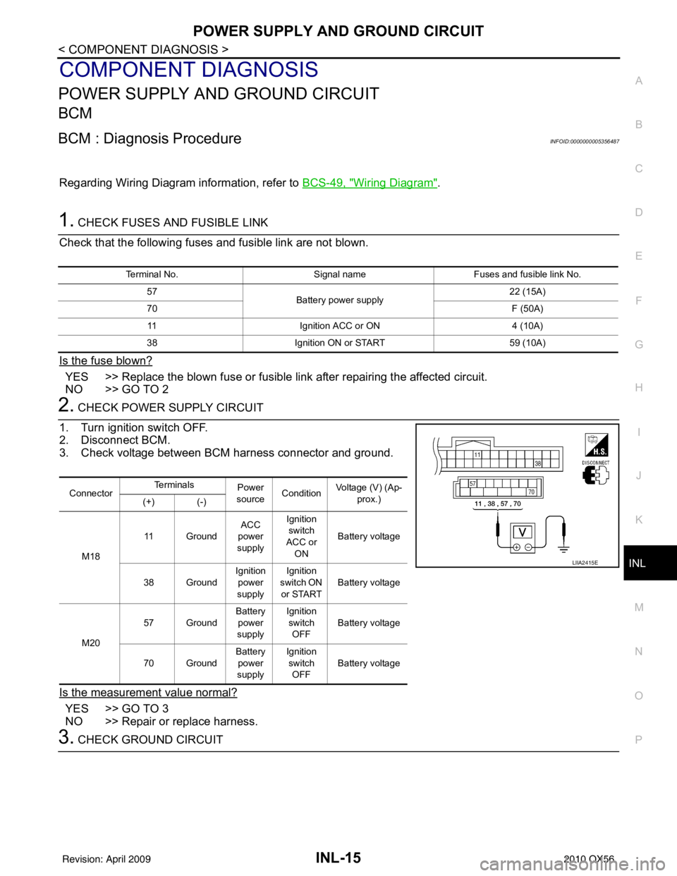
2. CHECK POWER SUPPLY CIRCUIT
1. Turn ignition switch OFF.
2. Disconnect BCM.
3. Check voltage between BCM harness connector and ground.
Is the measurement value normal?
YES >> GO TO 3
NO >> Repair or replace harness.
3. CHECK GROUND CIRCUIT
Terminal No. Signal nameFuses and fusible link No.
57 Battery power supply 22 (15A)
70 F (50A)
11 Ignition ACC or ON 4 (10A)
38 Ignition ON or START 59 (10A)
ConnectorTe r m i n a l s
Power
source Condition Voltage (V) (Ap-
prox.)
(+) (-)
M18 11 Ground
ACC
power
supply Ignition
switch
ACC or ON Battery voltage
38 Ground Ignition
power
supply Ignition
switch ON
or START Battery voltage
M20 57 Ground
Battery
power
supply Ignition
switch OFF Battery voltage
70 Ground Battery
power
supply Ignition
switch OFF Battery voltage
LIIA2415E
Revision: April 20092010 QX56
Page 2486 of 4210
BATTERY SAVER OUTPUT/POWER SUPPLY CIRCUITINL-17
< COMPONENT DIAGNOSIS >
C
DE
F
G H
I
J
K
M A
B
INL
N
O P
BATTERY SAVER OUTPUT/POWER SUPPLY CIRCUIT
DescriptionINFOID:0000000005146727
Provides the battery saver output/power supply. Also cu ts the power supply when the interior room lamp bat-
tery saver is activating.
Component Function CheckINFOID:0000000005146728
1.CHECK BATTERY SAVER OUTPUT /POWER SUPPLY FUNCTION
CONSULT-III
1. Turn ignition switch ON.
2. Turn each interior room lamp ON.
- Front room/map lamp assembly
- Vanity lamps
- Personal lamp 2nd row
- Personal lamp 3rd row
- Cargo lamp
3. Open the driver door to turn ON the step lamps, foot lamps and puddle lamps.
- Front step lamps
- Rear step lamps
- Foot lamps
- Puddle lamps
- Ignition keyhole Illumination
4. Select “BATTERY SAVER” of BCM (BATTERY SAVER) active test item.
5. While operating the test item, check that each interior room lamp turns ON/OFF.
Is the inspection result normal?
YES >> Battery saver output/power supply circuit is normal.
NO >> Refer to INL-17, "
Diagnosis Procedure".
Diagnosis ProcedureINFOID:0000000005146729
Regarding Wiring Diagram information, refer to BCS-49, "Wiring Diagram".
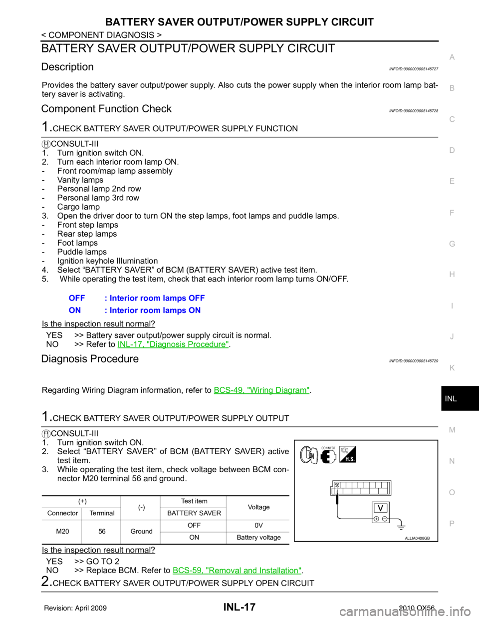
1.CHECK BATTERY SAVER OUTPUT/POWER SUPPLY OUTPUT
CONSULT-III
1. Turn ignition switch ON.
2. Select “BATTERY SAVER” of BCM (BATTERY SAVER) active
test item.
3. While operating the test item, check voltage between BCM con-
nector M20 terminal 56 and ground.
Is the inspection result normal?
YES >> GO TO 2
NO >> Replace BCM. Refer to BCS-59, "
Removal and Installation".
2.CHECK BATTERY SAVER OUTPUT/P OWER SUPPLY OPEN CIRCUIT
OFF : Interior room lamps OFF
ON : Interior room lamps ON
(+)
(-)Te s t i t e m
Voltag e
Connector Terminal BATTERY SAVER
M20 56 Ground OFF
0V
ON Battery voltage
ALLIA0408GB
Revision: April 20092010 QX56
Page 2487 of 4210
INL-18
< COMPONENT DIAGNOSIS >
BATTERY SAVER OUTPUT/POWER SUPPLY CIRCUIT
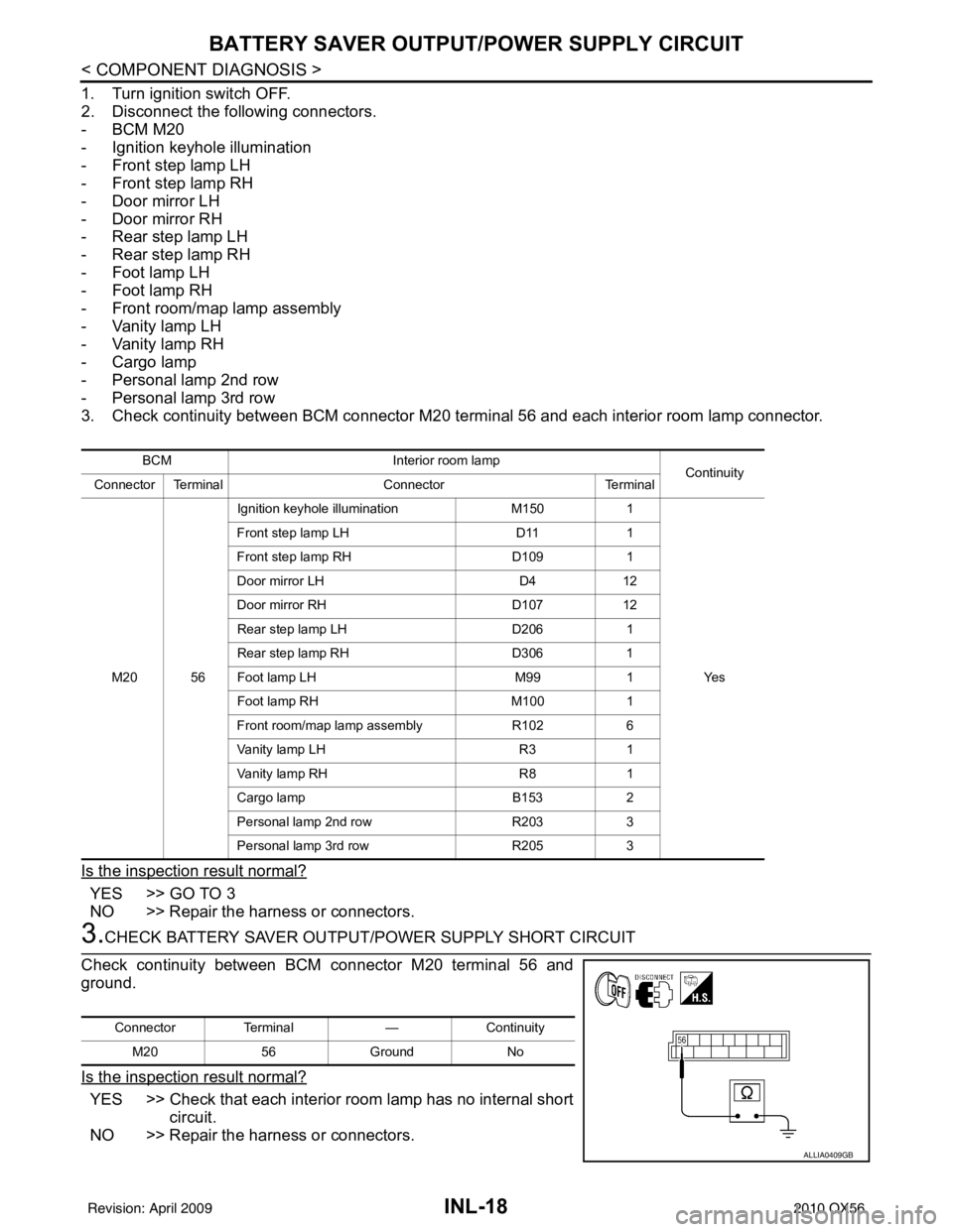
1. Turn ignition switch OFF.
2. Disconnect the following connectors.
-BCM M20
- Ignition keyhole illumination
- Front step lamp LH
- Front step lamp RH
- Door mirror LH
- Door mirror RH
- Rear step lamp LH
- Rear step lamp RH
- Foot lamp LH
- Foot lamp RH
- Front room/map lamp assembly
- Vanity lamp LH
- Vanity lamp RH
- Cargo lamp
- Personal lamp 2nd row
- Personal lamp 3rd row
3. Check continuity between BCM connector M20 terminal 56 and each interior room lamp connector.
Is the inspection result normal?
YES >> GO TO 3
NO >> Repair the harness or connectors.
3.CHECK BATTERY SAVER OUTPUT/P OWER SUPPLY SHORT CIRCUIT
Check continuity between BCM connector M20 terminal 56 and
ground.
Is the inspection result normal?
YES >> Check that each interior room lamp has no internal short circuit.
NO >> Repair the harness or connectors.
BCM Interior room lamp
Continuity
Connector Terminal ConnectorTerminal
M20 56 Ignition keyhole illumination
M1501
Ye s
Front step lamp LH
D111
Front step lamp RH D1091
Door mirror LH D412
Door mirror RH D10712
Rear step lamp LH D2061
Rear step lamp RH D3061
Foot lamp LH M991
Foot lamp RH M1001
Front room/map lamp assembly R1026
Vanity lamp LH R31
Vanity lamp RH R81
Cargo lamp B1532
Personal lamp 2nd row R2033
Personal lamp 3rd row R2053
Connector Terminal —Continuity
M20 56Ground No
ALLIA0409GB
Revision: April 20092010 QX56
Page 2488 of 4210
INTERIOR ROOM LAMP CONTROL CIRCUITINL-19
< COMPONENT DIAGNOSIS >
C
DE
F
G H
I
J
K
M A
B
INL
N
O P
INTERIOR ROOM LAMP CONTROL CIRCUIT
DescriptionINFOID:0000000005146730
Controls the following interior room lamps (ground side) by PWM signal
• Puddle lamps
• Front room/map lamp assembly
• Personal lamp 2nd row
• Personal lamp 3rd row
NOTE:
PWM signal control period is approximately 250 Hz (in the gradual brightening/dimming).
Component Function CheckINFOID:0000000005146731
CAUTION:
Before performing the diagnosis, check that the following is normal.
• Battery saver output/power supply
• Front room/map lamp bulbs
• Personal lamp bulbs
• Puddle lamp bulbs
1.CHECK INTERIOR ROOM LAMP CONTROL FUNCTION
CONSULT-III
1. Switch the front room/map lamp assembly switch to DOOR.
2. Turn ignition switch ON.
3. Select “INT LAMP” of BCM (INT LAMP) active test item.
4. While operating the test item, check that each interi or room lamp turns ON/OFF (gradual brightening/dim-
ming).
Is the inspection result normal?
YES >> Interior room lamp control circuit is normal.
NO >> Refer to INL-19, "
Diagnosis Procedure".
Diagnosis ProcedureINFOID:0000000005146732
Regarding Wiring Diagram information, refer to INL-28, "Wiring Diagram".
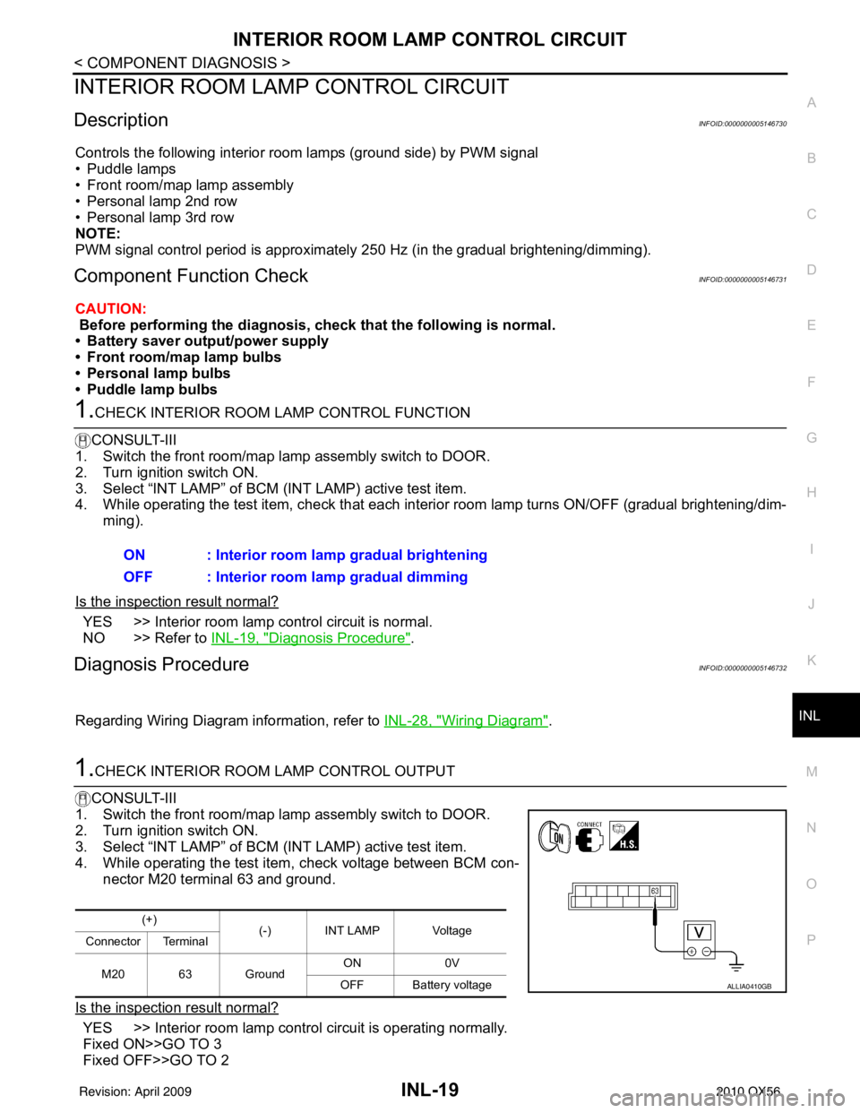
1.CHECK INTERIOR ROOM LAMP CONTROL OUTPUT
CONSULT-III
1. Switch the front room/map lamp assembly switch to DOOR.
2. Turn ignition switch ON.
3. Select “INT LAMP” of BCM (INT LAMP) active test item.
4. While operating the test item, check voltage between BCM con- nector M20 terminal 63 and ground.
Is the inspection result normal?
YES >> Interior room lamp control circuit is operating normally.
Fixed ON>>GO TO 3
Fixed OFF>>GO TO 2 ON : Interior room lamp gradual brightening
OFF : Interior room lamp gradual dimming
(+)
(-) INT LAMP Voltage
Connector Terminal
M20 63 Ground ON
0V
OFF Battery voltage
ALLIA0410GB
Revision: April 20092010 QX56