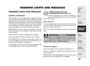
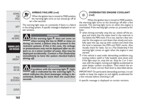
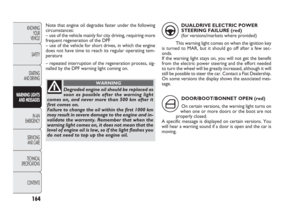
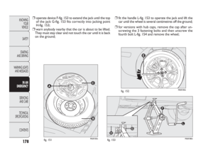
Page 97 of 270

F0U0095mfig. 104
Make sure the backrest is properly secured at both sides
to prevent it moving forward in the event of sharp brak-
ing that may cause injuries to passengers.
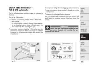
REMOVING THE PARCEL SHELF
To remove the parcel shelf in order to extend the boot:
release the upper ends A-fig. 105 by removing the eye-
lets from the pins, unhook and swivel the parcel shelf in
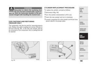
its housing and then release both pins fig. 106 from the
side holes. Repositioning the rear seat fig. 104
Raise the backrests and push them back until hearing the
locking click of both retainers.
Position the seat belt buckles upwards and set the cush-
ion to the position of normal use.
IMPORTANT The backrest is correctly secured when the
red band next to the handles disappears. This red band in-
dicates that the backrest is not secured. When returning
the backrest to its normal position, make sure it is cor-
rectly fastened and you hear the lock click.
96
KNOWING
YOUR
VEHICLE
SAFETY
STARTING
AND DRIVING
WARNING LIGHTS
AND MESSAGES
IN AN
EMERGENCY
SERVICING
AND CARE
TECHNICAL
SPECIFICATIONS
CONTENTS
F0U0097mfig. 105
082-128 PUNTO FL EN 4ed 20-01-2010 15:06 Pagina 96
Page 98 of 270
97
F0U0096mfig. 107
KNOWING
YOUR
VEHICLE
SAFETY
STARTING
AND DRIVING
WARNING LIGHTS
AND MESSAGES
IN AN
EMERGENCY
SERVICING
AND CARE
TECHNICAL
SPECIFICATIONS
CONTENTS
F0U0098mfig. 106
Once removed, the parcel shelf can be positioned between
the back of the front seats and the folded cushion of the
rear seat fig. 107.
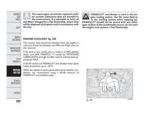
F0U0100mfig. 108
BONNET
OPENING
Proceed as follows:
❒pull the lever fig. 108 in the direction of the arrow;
❒pull the catch A-fig. 109 as shown in the diagram;
❒lift the bonnet and, at the same time, release the bon-
net support rod from its locking device D-fig. 110; then
insert the end of the bonnet support rod C-fig. 111 in-
to the hole E.
IMPORTANT Before opening the bonnet, check that wind-
screen wiper arms are not lifted from the windscreen.
082-128 PUNTO FL EN 4ed 20-01-2010 15:06 Pagina 97
Page 99 of 270

F0U0101mfig. 109
CLOSING
Proceed as follows:
❒hold the bonnet up with one hand and with the other
remove the rod C-fig. 111 from the hole E and fit it
back into its catch D-fig. 110;
❒lower the bonnet to approximately 20 centimetres from
the engine compartment, then let it drop. Make sure
that the bonnet is completely closed and not fastened
only by the safety catch. If it is not perfectly closed, do
not try to press the bonnet lid down but open it and re-
peat the procedure.
IMPORTANT Always check that the bonnet is closed
properly to avoid it opening while the car is travelling.
98
KNOWING
YOUR
VEHICLE
SAFETY
STARTING
AND DRIVING
WARNING LIGHTS
AND MESSAGES
IN AN
EMERGENCY
SERVICING
AND CARE
TECHNICAL
SPECIFICATIONS
CONTENTS
F0U0102mfig. 110
For safety reasons, the bonnet must al-
ways be perfectly closed while travelling.
Make sure that the bonnet is perfectly closed and
that the lock is engaged. If you notice whilst dri-
ving that the lock is not perfectly engaged, stop
at once and close the bonnet properly.
WARNING
082-128 PUNTO FL EN 4ed 20-01-2010 15:06 Pagina 98
Page 100 of 270
99
KNOWING
YOUR
VEHICLE
SAFETY
STARTING
AND DRIVING
WARNING LIGHTS
AND MESSAGES
IN AN
EMERGENCY
SERVICING
AND CARE
TECHNICAL
SPECIFICATIONS
CONTENTS
Positioning the support rod incorrectly
could cause the bonnet to fall suddenly.
WARNING
F0U0103mfig. 111
Perform these operations only when the
car is stationary.
WARNING
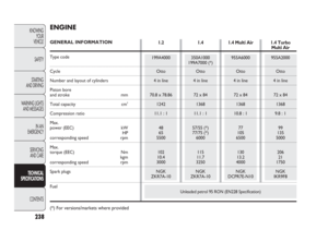
F0U0104mfig. 112
ROOF RACK/SKI RACK
3-door versions
The front hooks are located at points A-fig. 112.
The rear hooks are located at points B marked by the (
O)
symbols on the rear side windows.
5-door versions
The front hooks are located at points A-fig. 112.
The rear hooks are located at points B and are marked
by a groove on the upper part of the door frame.
082-128 PUNTO FL EN 4ed 20-01-2010 15:06 Pagina 99
Page 101 of 270
IMPORTANT Follow the instructions contained in the as-
sembly kit carefully. Assembly must be performed by qual-
ified personnel.
100
KNOWING
YOUR
VEHICLE
SAFETY
STARTING
AND DRIVING
WARNING LIGHTS
AND MESSAGES
IN AN
EMERGENCY
SERVICING
AND CARE
TECHNICAL
SPECIFICATIONS
CONTENTS
After travelling a short distance, check that
the coupling fastening screws are tight.
WARNING
Distribute the load evenly and, when dri-
ving, bear in mind the increased sensitivi-
ty of the vehicle to side wind.
WARNING
Strictly comply with current legal regula-
tions concerning maximum overall dimen-
sions.Never exceed the permitted load (see
“Technical specifications” section).
082-128 PUNTO FL EN 4ed 20-01-2010 15:06 Pagina 100
Page 102 of 270

101
KNOWING
YOUR
VEHICLE
SAFETY
STARTING
AND DRIVING
WARNING LIGHTS
AND MESSAGES
IN AN
EMERGENCY
SERVICING
AND CARE
TECHNICAL
SPECIFICATIONS
CONTENTS
F0U0105mfig. 113
Headlight alignment adjustment fig. 113
To adjust, press buttons Òand on the control panel.
The display located on the instrument panel provides the
visual indication of the positions during the adjustment op-
eration.
Position 0 – one or two people in the front seats.
Position 1 – five people.
Position 2 – five people + load in the boot.
Position 3 – driver + maximum permitted load stowed in
the boot.
IMPORTANT Check the beam alignment every time the
load transported changes.
FRONT FOG LIGHTS ALIGNMENT
(for versions/markets where provided)
Contact a Fiat Dealership to have the direction checked
and, if necessary, adjusted.HEADLIGHTS
LIGHT BEAM DIRECTION
The correct direction of the headlights is essential for the
comfort and safety of the driver and other road users. The
headlights must be correctly directed to ensure the best
visibility. Contact a Fiat Dealership to have the direction
checked and, if necessary, adjusted.
HEADLIGHT ALIGNMENT CORRECTOR
This device works with the key in the MAR position and
the dipped headlights on. The car will tilt backwards when
it is loaded, raising the light beam. The beams must there-
fore be aimed again in this case.
082-128 PUNTO FL EN 4ed 20-01-2010 15:06 Pagina 101
Page 103 of 270
102
KNOWING
YOUR
VEHICLE
SAFETY
STARTING
AND DRIVING
WARNING LIGHTS
AND MESSAGES
IN AN
EMERGENCY
SERVICING
AND CARE
TECHNICAL
SPECIFICATIONS
CONTENTS
HEADLIGHT BEAM ADJUSTMENT ABROAD
fig. 114-115
The dipped headlights are adjusted to work in the coun-
try where the vehicle was originally purchased. In coun-
tries where vehicles are driven on the other side of the
road, the beams are aligned by applying a specially designed
adhesive film in order not to dazzle the vehicles travel-
ling in the opposite direction.
16569R 151
50
130
F0U0506mfig. 114F0U0346mfig. 115
Such film is provided by Lineaccessori Fiat and is available
at Fiat Dealerships.
The illustrations refer to the changeover from driving on
the left to driving on the right.
082-128 PUNTO FL EN 4ed 20-01-2010 15:06 Pagina 102
Page 104 of 270

103
KNOWING
YOUR
VEHICLE
SAFETY
STARTING
AND DRIVING
WARNING LIGHTS
AND MESSAGES
IN AN
EMERGENCY
SERVICING
AND CARE
TECHNICAL
SPECIFICATIONS
CONTENTS
SYSTEM INTERVENTION
The driver can tell the ABS system has come into action
because the brake pedal pulsates slightly and the system
gets noisier: it means that the vehicle speed should be al-
tered to suit the type of road surface.ABS SYSTEM
If you have never driven a vehicle with ABS before, it is ad-
visable to perform a few tests on slippery ground, always
in safe conditions and respecting the highway code of the
country where you are driving. Read the following infor-
mation carefully.
This system, which is an integral part of the braking sys-
tem, prevents one or more wheels from locking and skid-
ding on all road surface conditions, irrespective of the in-
tensity of the braking action, ensuring that the vehicle can
be controlled even during emergency braking.
The system is completed by EBD (Electronic Braking Force
Distribution), which distributes the braking action between
the front and rear wheels.
IMPORTANT For the maximum efficiency of the braking
system, a bedding-in period of about 500 km is needed (for
a new vehicle or after having replaced the brake
pads/discs): during this period it is better to avoid sharp,
repeated and prolonged braking.
The ABS system gets the most out of the
available grip but it cannot improve it.
Therefore, you should take great care when
driving on slippery surfaces: don’t take unneces-
sary risks.
WARNING
If the ABS cuts in, it is a sign that the grip
between tyre and the road surface has
reached the limit: you must slow down to match
the speed to the road grip available.
WARNING
FAILURE INDICATIONS
ABS failure
ABS failure is indicated by warning light >coming on on
the instrument panel together with the dedicated message
on the multifunction display (where provided), (see “Warn-
ing lights and messages”).
In this case, the braking system will work as normal, but
without the extra capacity offered by the ABS system. Dri-
ve carefully to the nearest Fiat Dealership to have the sys-
tem checked.
EBD failure
EBD failure is indicated by warning lights >and xcom-
ing on on the instrument panel together with the dedicated
message on the multifunction display (where provided),
(see section “Warning lights and messages”).
082-128 PUNTO FL EN 4ed 20-01-2010 15:06 Pagina 103