2010 CHEVROLET SILVERADO ECO mode
[x] Cancel search: ECO modePage 222 of 626
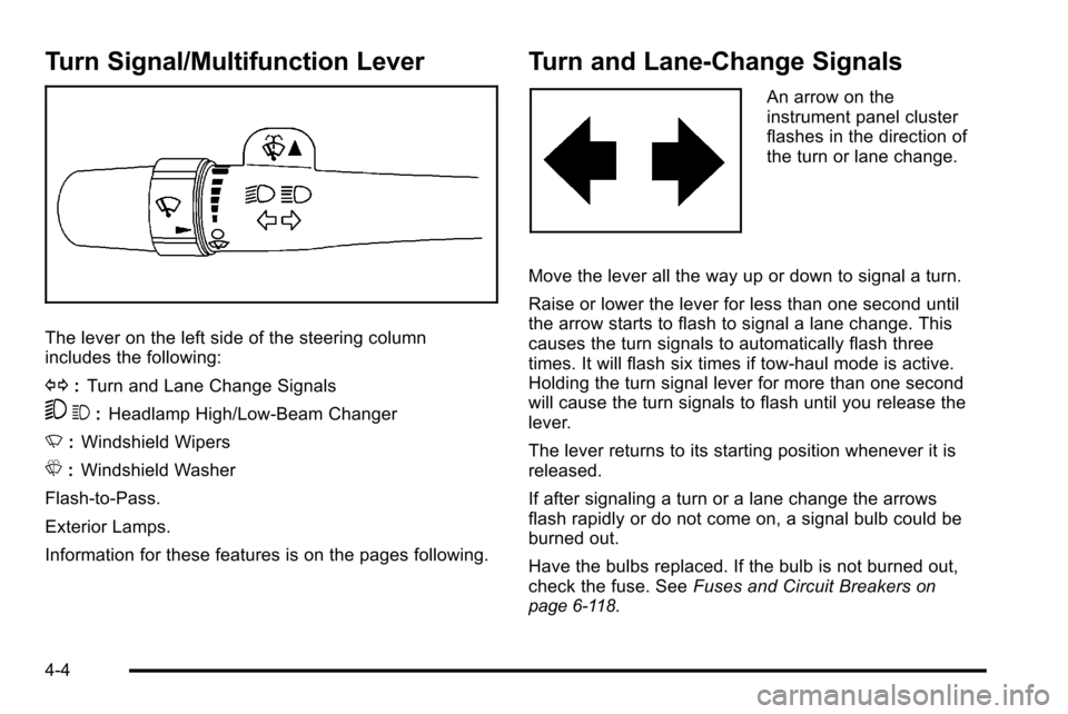
Turn Signal/Multifunction Lever
The lever on the left side of the steering column
includes the following:
G:Turn and Lane Change Signals
53 :Headlamp High/Low-Beam Changer
N :Windshield Wipers
L :Windshield Washer
Flash-to-Pass.
Exterior Lamps.
Information for these features is on the pages following.
Turn and Lane-Change Signals
An arrow on the
instrument panel cluster
flashes in the direction of
the turn or lane change.
Move the lever all the way up or down to signal a turn.
Raise or lower the lever for less than one second until
the arrow starts to flash to signal a lane change. This
causes the turn signals to automatically flash three
times. It will flash six times if tow-haul mode is active.
Holding the turn signal lever for more than one second
will cause the turn signals to flash until you release the
lever.
The lever returns to its starting position whenever it is
released.
If after signaling a turn or a lane change the arrows
flash rapidly or do not come on, a signal bulb could be
burned out.
Have the bulbs replaced. If the bulb is not burned out,
check the fuse. See Fuses and Circuit Breakers
on
page 6‑118.
4-4
Page 239 of 626
Climate Control System (With
Heater Only)
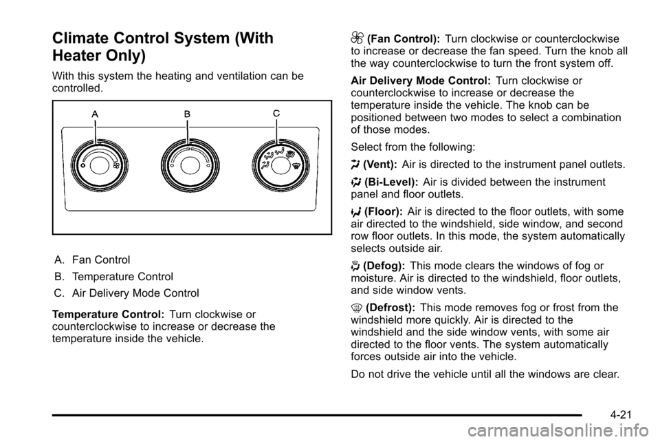
With this system the heating and ventilation can be
controlled.
A. Fan Control
B. Temperature Control
C. Air Delivery Mode Control
Temperature Control: Turn clockwise or
counterclockwise to increase or decrease the
temperature inside the vehicle.
9(Fan Control): Turn clockwise or counterclockwise
to increase or decrease the fan speed. Turn the knob all
the way counterclockwise to turn the front system off.
Air Delivery Mode Control: Turn clockwise or
counterclockwise to increase or decrease the
temperature inside the vehicle. The knob can be
positioned between two modes to select a combination
of those modes.
Select from the following:
H (Vent): Air is directed to the instrument panel outlets.
) (Bi-Level): Air is divided between the instrument
panel and floor outlets.
6 (Floor): Air is directed to the floor outlets, with some
air directed to the windshield, side window, and second
row floor outlets. In this mode, the system automatically
selects outside air.
- (Defog): This mode clears the windows of fog or
moisture. Air is directed to the windshield, floor outlets,
and side window vents.
0 (Defrost): This mode removes fog or frost from the
windshield more quickly. Air is directed to the
windshield and the side window vents, with some air
directed to the floor vents. The system automatically
forces outside air into the vehicle.
Do not drive the vehicle until all the windows are clear.
4-21
Page 241 of 626
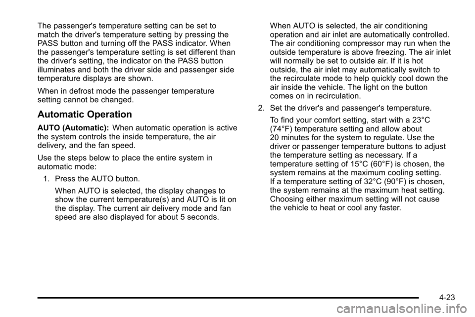
The passenger's temperature setting can be set to
match the driver's temperature setting by pressing the
PASS button and turning off the PASS indicator. When
the passenger's temperature setting is set different than
the driver's setting, the indicator on the PASS button
illuminates and both the driver side and passenger side
temperature displays are shown.
When in defrost mode the passenger temperature
setting cannot be changed.
Automatic Operation
AUTO (Automatic):When automatic operation is active
the system controls the inside temperature, the air
delivery, and the fan speed.
Use the steps below to place the entire system in
automatic mode:
1. Press the AUTO button.
When AUTO is selected, the display changes to
show the current temperature(s) and AUTO is lit on
the display. The current air delivery mode and fan
speed are also displayed for about 5 seconds. When AUTO is selected, the air conditioning
operation and air inlet are automatically controlled.
The air conditioning compressor may run when the
outside temperature is above freezing. The air inlet
will normally be set to outside air. If it is hot
outside, the air inlet may automatically switch to
the recirculate mode to help quickly cool down the
air inside the vehicle. The light on the button
comes on in recirculation.
2. Set the driver's and passenger's temperature. To find your comfort setting, start with a 23°C
(74°F) temperature setting and allow about
20 minutes for the system to regulate. Use the
driver or passenger temperature buttons to adjust
the temperature setting as necessary. If a
temperature setting of 15°C (60°F) is chosen, the
system remains at the maximum cooling setting.
If a temperature setting of 32°C (90°F) is chosen,
the system remains at the maximum heat setting.
Choosing either maximum setting will not cause
the vehicle to heat or cool any faster.
4-23
Page 242 of 626

Do not cover the solar sensor located on the top of the
instrument panel near the windshield. This sensor
regulates air temperature based on sun load. For more
information on the solar sensor, see“Sensors”later in
this section.
To avoid blowing cold air in cold weather, the system
delays turning the fan on until warm air is available. The
length of delay depends on the engine coolant
temperature. Pressing the fan switch overrides this
delay and changes the fan to a selected speed.
Manual Operation
D C(Fan Control): Press these buttons to increase or
decrease the fan speed.
Pressing either fan button while in automatic control
places the fan under manual control. The fan setting
remains displayed and the AUTO light turns off. The air
delivery mode remains under automatic control.
H G(Air Delivery Mode Control): Press these buttons
to change the direction of the airflow in the vehicle.
Repeatedly press either button until the desired mode
appears on the display. Pressing either mode button
while the system is off changes the air delivery mode
without turning the system on. Pressing either mode
button while in automatic control places the mode under
manual control. The air delivery mode setting is displayed and the
AUTO light turns off. The fan remains under automatic
control.
H(Vent):
Air is directed to the instrument panel
outlets.
)(Bi-Level): Air is divided between the instrument
panel and floor outlets. Some air is directed towards the
windshield and side window outlets.
6(Floor): Air is directed to the floor outlets, with some
to the windshield, side window outlets, and second row
floor outlets. In this mode, the system automatically
selects outside air.
-(Defog): This mode clears the windows of fog or
moisture. Air is directed to the windshield, floor outlets,
and side window vents. In this mode, the system turns
off recirculation and runs the air conditioning
compressor unless the outside temperature is close to
freezing. The recirculation mode cannot be selected
while in the defrost mode.
4-24
Page 248 of 626
Speedometer and Odometer
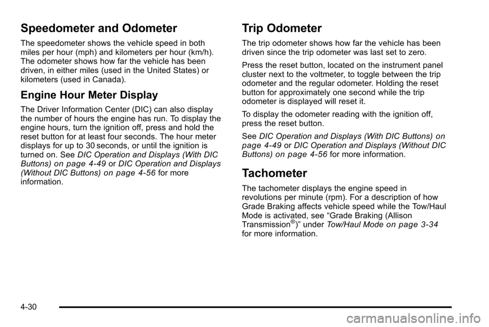
The speedometer shows the vehicle speed in both
miles per hour (mph) and kilometers per hour (km/h).
The odometer shows how far the vehicle has been
driven, in either miles (used in the United States) or
kilometers (used in Canada).
Engine Hour Meter Display
The Driver Information Center (DIC) can also display
the number of hours the engine has run. To display the
engine hours, turn the ignition off, press and hold the
reset button for at least four seconds. The hour meter
displays for up to 30 seconds, or until the ignition is
turned on. SeeDIC Operation and Displays (With DIC
Buttons)
on page 4‑49or DIC Operation and Displays
(Without DIC Buttons)on page 4‑56for more
information.
Trip Odometer
The trip odometer shows how far the vehicle has been
driven since the trip odometer was last set to zero.
Press the reset button, located on the instrument panel
cluster next to the voltmeter, to toggle between the trip
odometer and the regular odometer. Holding the reset
button for approximately one second while the trip
odometer is displayed will reset it.
To display the odometer reading with the ignition off,
press the reset button.
See DIC Operation and Displays (With DIC Buttons)
on
page 4‑49or DIC Operation and Displays (Without DIC
Buttons)on page 4‑56for more information.
Tachometer
The tachometer displays the engine speed in
revolutions per minute (rpm). For a description of how
Grade Braking affects vehicle speed while the Tow/Haul
Mode is activated, see “Grade Braking (Allison
Transmission
®)” under Tow/Haul Modeon page 3‑34for more information.
4-30
Page 254 of 626
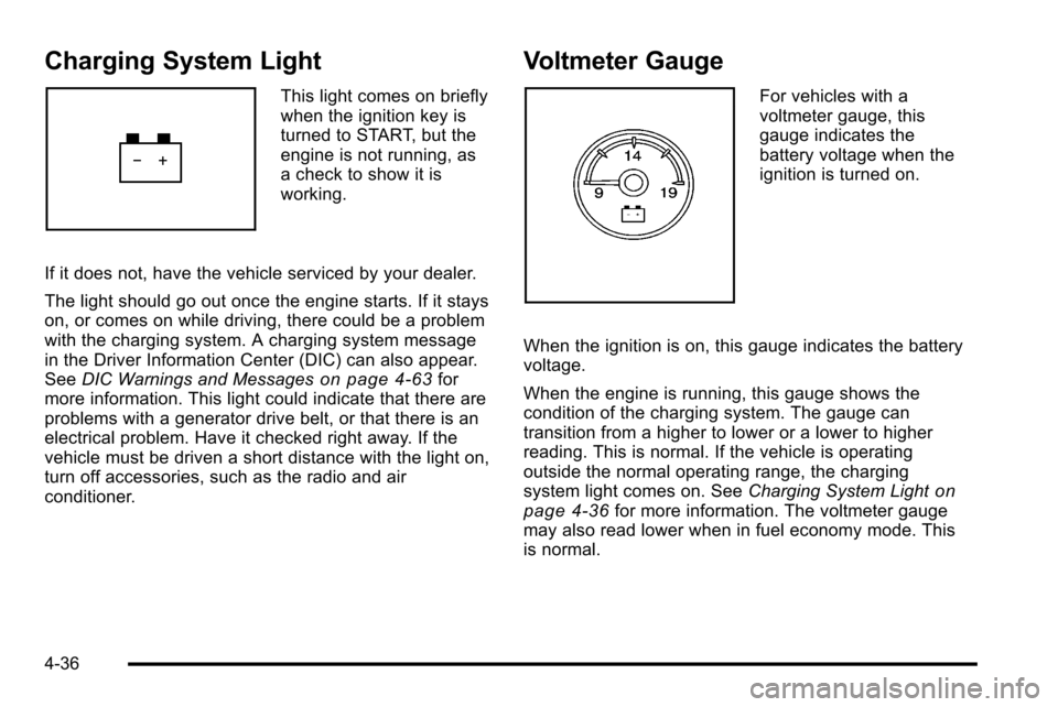
Charging System Light
This light comes on briefly
when the ignition key is
turned to START, but the
engine is not running, as
a check to show it is
working.
If it does not, have the vehicle serviced by your dealer.
The light should go out once the engine starts. If it stays
on, or comes on while driving, there could be a problem
with the charging system. A charging system message
in the Driver Information Center (DIC) can also appear.
See DIC Warnings and Messages
on page 4‑63for
more information. This light could indicate that there are
problems with a generator drive belt, or that there is an
electrical problem. Have it checked right away. If the
vehicle must be driven a short distance with the light on,
turn off accessories, such as the radio and air
conditioner.
Voltmeter Gauge
For vehicles with a
voltmeter gauge, this
gauge indicates the
battery voltage when the
ignition is turned on.
When the ignition is on, this gauge indicates the battery
voltage.
When the engine is running, this gauge shows the
condition of the charging system. The gauge can
transition from a higher to lower or a lower to higher
reading. This is normal. If the vehicle is operating
outside the normal operating range, the charging
system light comes on. See Charging System Light
on
page 4‑36for more information. The voltmeter gauge
may also read lower when in fuel economy mode. This
is normal.
4-36
Page 272 of 626
If the tire pressure display shows dashes instead of a
value, there may be a problem with your vehicle. If this
consistently occurs, see your dealer for service.
Trailer Gain and Output
On vehicles with the Integrated Trailer Brake Control
(ITBC) system, the trailer brake display appears in the
DIC. Press the vehicle information button until TRAILER
GAIN and OUTPUT display.
TRAILER GAIN shows the trailer gain setting. This
setting can be adjusted from 0.0 to 10.0 with either a
trailer connected or disconnected. To adjust this setting,
see“Integrated Trailer Brake Control System” under
Towing a Trailer
on page 5‑51for more information.
OUTPUT shows the power output to the trailer anytime
a trailer with electric brakes is connected. Output is
displayed in 0 to 10 bars. Dashes may appear in the
OUTPUT display. See “Integrated Trailer Brake Control
System” underTowing a Trailer
on page 5‑51for more
information.
Engine Hours
Press the vehicle information button until ENGINE
HOURS displays. This display shows the total number
of hours the engine has run.
Relearn Remote Key
This display allows you to match Remote Keyless Entry
(RKE) transmitters to your vehicle. This procedure will
erase all previously learned transmitters. Therefore,
they must be relearned as additional transmitters.
To match an RKE transmitter to your vehicle:
1. Press the vehicle information button until PRESS
VTO RELEARN REMOTE KEY displays.
2. Press the set/reset button until REMOTE KEY LEARNING ACTIVE is displayed.
3. Press and hold the lock and unlock buttons on the first transmitter at the same time for about
15 seconds.
On vehicles with memory recall seats, the first
transmitter learned will match driver 1 and the
second will match driver 2.
A chime will sound indicating that the transmitter is
matched.
4. To match additional transmitters at this time, repeat Step 3.
Each vehicle can have a maximum of eight
transmitters matched to it.
5. To exit the programming mode, you must cycle the key to LOCK/OFF.
4-54
Page 277 of 626

Remember, you must reset the OIL LIFE display
yourself after each oil change. It will not reset itself.
Also, be careful not to reset the OIL LIFE display
accidentally at any time other than when the oil has just
been changed. It cannot be reset accurately until the
next oil change. To reset the engine oil life system, see
Engine Oil Life System on page 6‑20.
Relearn Tire Positions
Your vehicle may have this display. To access this
display, the vehicle must be in P (Park). If your vehicle
has the Tire Pressure Monitor System (TPMS), after
rotating the tires or after replacing a tire or sensor, the
system must re-learn the tire positions. To re-learn the
tire positions, seeTire Pressure Monitor System
on
page 6‑75. See Tire Inspection and Rotationon
page 6‑80and DIC Warnings and Messageson
page 4‑63for more information.
Relearn Remote Key
To access this display, the vehicle must be in P (Park).
This display allows you to match Remote Keyless Entry
(RKE) transmitters to your vehicle. This procedure will
erase all previously learned transmitters. Therefore,
they must be relearned as additional transmitters. To match an RKE transmitter to your vehicle:
1. Press the trip odometer reset stem until RELEARN REMOTE KEY displays.
2. Press and hold the trip odometer reset stem for three seconds.
The message REMOTE KEY LEARNING ACTIVE
will display.
3. Press and hold the lock and unlock buttons on the first transmitter at the same time for about
15 seconds.
On vehicles with memory recall seats, the first
transmitter learned will match driver 1 and the
second will match driver 2.
A chime will sound indicating that the transmitter is
matched.
4. To match additional transmitters at this time, repeat Step 3.
Each vehicle can have a maximum of eight
transmitters matched to it.
5. To exit the programming mode, you must cycle the key to LOCK/OFF.
4-59