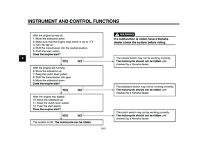
Page 49 of 94

PERIODIC MAINTENANCE AND ADJUSTMENT
6-4
2
3
4
5
67
8
9
19
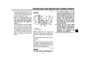
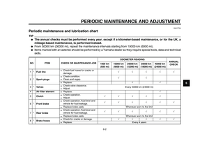
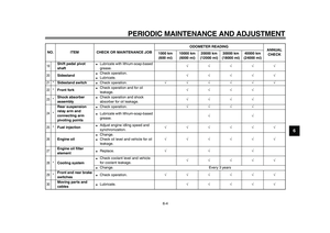
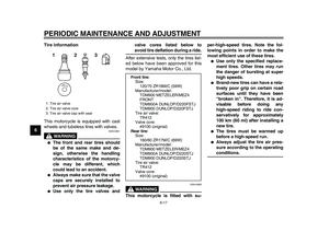
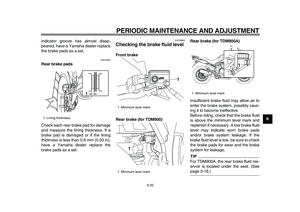
Shift pedal pivot
shaft
●
Lubricate with lithium-soap-based
grease.
√√√√√
20
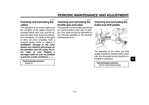
Sidestand
●
Check operation.
●
Lubricate.
√√√√√
21
*
Sidestand switch
●
Check operation.
√√√√√√
22
*
Front fork
●
Check operation and for oil
leakage.
√√√√
23
*
Shock absorber
assembly
●
Check operation and shock
absorber for oil leakage.
√√√√
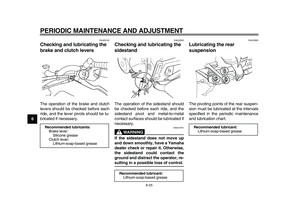
24
*
Rear suspension
relay arm and
connecting arm
pivoting points
●
Check operation.
√√√√
●
Lubricate with lithium-soap-based
grease.
√√
25
*
Fuel injection
●
Adjust engine idling speed and
synchronization.
√√√√√√
26
Engine oil
●
Change.
●
Check oil level and vehicle for oil
leakage.
√√√√√√
27
Engine oil filter
element
●
Replace.
√√√
28
*
Cooling system
●
Check coolant level and vehicle
for coolant leakage.
√√√√√
●
Change. Every 3 years
29
*
Front and rear brake
switches
●
Check operation.
√√√√√√
30
Moving parts and
cables
●
Lubricate.
√√√√√
NO. ITEM CHECK OR MAINTENANCE JOBODOMETER READING
ANNUAL
CHECK 1000 km
(600 mi)10000 km
(6000 mi)20000 km
(12000 mi)30000 km
(18000 mi)40000 km
(24000 mi)
Page 50 of 94

PERIODIC MAINTENANCE AND ADJUSTMENT
6-5
1
2
3
4
5
6
7
8
9
EAU18680
TIP
●
Air filter
●
This model’s air filter is equipped with a disposable oil-coated paper element, which must not be cleaned with com-
pressed air to avoid damaging it.
●
The air filter element needs to be replaced more frequently when riding in unusually wet or dusty areas.
●
Hydraulic brake service
●
Regularly check and, if necessary, correct the brake fluid level.
●
Every two years replace the internal components of the brake master cylinders and calipers, and change the brake
fluid.
●
Replace the brake hoses every four years and if cracked or damaged.
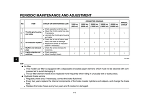
31
*
Throttle grip housing
and cable
●
Check operation and free play.
●
Adjust the throttle cable free play
if necessary.
●
Lubricate the throttle grip housing
and cable.
√√√√√
32
*
Air induction system
●
Check the air cut-off valve, reed
valve, and hose for damage.
●
Replace the entire air induction
system if necessary.
√√√√√
33
*
Muffler and exhaust
pipe
●
Check the screw clamp(s) for
looseness.
√√√√√
34
*
Lights, signals and
switches
●
Check operation.
●
Adjust headlight beam.
√√√√√√
NO. ITEM CHECK OR MAINTENANCE JOBODOMETER READING
ANNUAL
CHECK 1000 km
(600 mi)10000 km
(6000 mi)20000 km
(12000 mi)30000 km
(18000 mi)40000 km
(24000 mi)
Page 51 of 94
PERIODIC MAINTENANCE AND ADJUSTMENT
6-6
2
3
4
5
67
8
9
EAU18712
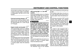
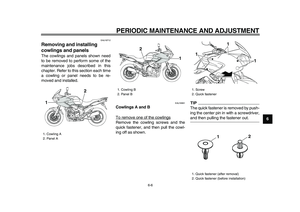
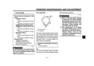
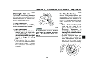
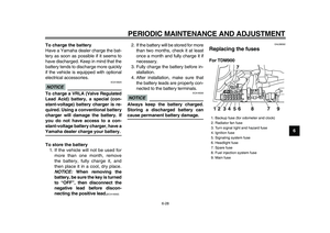
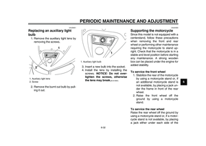
Removing and installing
cowlings and panels
The cowlings and panels shown need
to be removed to perform some of the
maintenance jobs described in this
chapter. Refer to this section each time
a cowling or panel needs to be re-
moved and installed.
EAU18991
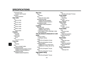
Cowlings A and B
To remove one of the cowlings
Remove the cowling screws and the
quick fastener, and then pull the cowl-
ing off as shown.
TIP
The quick fastener is removed by push-
ing the center pin in with a screwdriver,
and then pulling the fastener out.
1. Cowling A
2. Panel A
2
1
1. Cowling B
2. Panel B2
1
1. Screw
2. Quick fastener
1. Quick fastener (after removal)
2. Quick fastener (before installation)
1
1
1
2
12
Page 52 of 94

PERIODIC MAINTENANCE AND ADJUSTMENT
6-7
1
2
3
4
5
6
7
8
9
To install the cowling
Place the cowling in the original posi-
tion, and then install the screws and the
quick fastener.TIP
To install the quick fastener, push the
center pin out so that it will protrude
from the fastener head, insert the fas-
tener into the cowling, and then push
the protruding pin in until it is flush with
the fastener head.
EAU19171
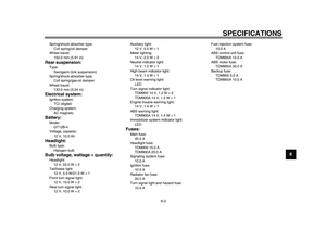
Panels A and B
To remove one of the panels
1. Remove the corresponding cowl-
ing A or B. (See page 6-6.)
2. Remove the seat. (See
page 3-16.)
3. Remove the screw, and then take
the panel off.To install the panel
1. Place the panel in the original po-
sition, and then install the screw.
2. Install the seat and the cowling.
EAU19642
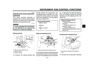
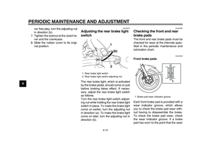
Checking the spark plugs
The spark plugs are important engine
components, which should be checked
periodically, preferably by a Yamaha
dealer. Since heat and deposits will
cause any spark plug to slowly erode,
they should be removed and checked
in accordance with the periodic mainte-
nance and lubrication chart. In addition,
the condition of the spark plugs can re-
veal the condition of the engine.
The porcelain insulator around the cen-
ter electrode of each spark plug should
be a medium-to-light tan (the ideal color
when the vehicle is ridden normally),
and all spark plugs installed in the en-
gine should have the same color. If any
spark plug shows a distinctly different
color, the engine could be operating im-
properly. Do not attempt to diagnose
such problems yourself. Instead, have
a Yamaha dealer check the vehicle.
If a spark plug shows signs of electrode
erosion and excessive carbon or other
deposits, it should be replaced.
1. Screw
1. Panel A
1
1
Page 53 of 94

PERIODIC MAINTENANCE AND ADJUSTMENT
6-8
2
3
4
5
67
8
9
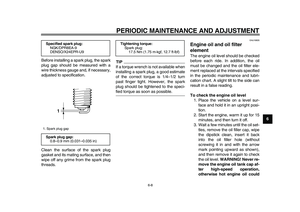
Before installing a spark plug, the spark
plug gap should be measured with a
wire thickness gauge and, if necessary,
adjusted to specification.
Clean the surface of the spark plug
gasket and its mating surface, and then
wipe off any grime from the spark plug
threads.
TIP
If a torque wrench is not available when
installing a spark plug, a good estimate
of the correct torque is 1/4–1/2 turn
past finger tight. However, the spark
plug should be tightened to the speci-
fied torque as soon as possible.
EAU19835
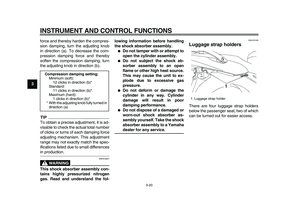
Engine oil and oil filter
element
The engine oil level should be checked
before each ride. In addition, the oil
must be changed and the oil filter ele-
ment replaced at the intervals specified
in the periodic maintenance and lubri-
cation chart. A slight tilt to the side can
result in a false reading.
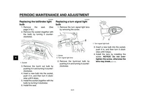
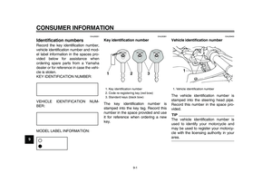
To check the engine oil level
1. Place the vehicle on a level sur-
face and hold it in an upright posi-
tion.
2. Start the engine, warm it up for 15
minutes, and then turn it off.
3. Wait a few minutes until the oil set-
tles, remove the oil filler cap, wipe
the dipstick clean, insert it back
into the oil filler hole (without
screwing it in and with the arrow
mark pointing upward as shown),
and then remove it again to check
the oil level.
WARNING! Never re-
move the engine oil tank cap af-
ter high-speed operation,
otherwise hot engine oil could
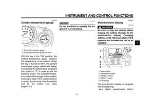
Specified spark plug:
NGK/DPR8EA-9
DENSO/X24EPR-U9
1. Spark plug gap
Spark plug gap:
0.8–0.9 mm (0.031–0.035 in)
1
Tightening torque:
Spark plug:
17.5 Nm (1.75 m·kgf, 12.7 ft·lbf)
Page 54 of 94
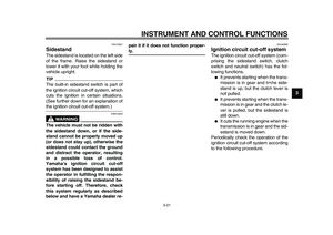
![YAMAHA TDM 900 2009 Owners Manual
PERIODIC MAINTENANCE AND ADJUSTMENT
6-9
1
2
3
4
5
6
7
8
9spout out and cause damage or
injury. Always let the engine oil
cool down sufficiently before re-
moving the oil tank cap.
[EWA10361]
NO](/manual-img/51/51368/w960_51368-53.png "YAMAHA TDM 900 2009 Owners Manual
PERIODIC MAINTENANCE AND ADJUSTMENT
6-9
1
2
3
4
5
6
7
8
9spout out and cause damage or
injury. Always let the engine oil
cool down sufficiently before re-
moving the oil tank cap.
[EWA10361]
NO")
PERIODIC MAINTENANCE AND ADJUSTMENT
6-9
1
2
3
4
5
6
7
8
9spout out and cause damage or
injury. Always let the engine oil
cool down sufficiently before re-
moving the oil tank cap.
[EWA10361]
NOTICE:
Do not operate the ve-
hicle until you know that the en-
gine oil level is sufficient.
[ECA10011]
TIP
The engine oil should be between the
minimum and maximum level marks.
4. If the engine oil is below the mini-
mum level mark, add sufficient oil
of the recommended type to raise
it to the correct level.
5. Install the oil filler cap.
TIP
●
The engine oil tank is located be-
hind the cylinders.
●
The engine oil should be between
the minimum and maximum level
marks.
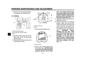
To change the engine oil (with or
without oil filter element replace-
ment)
1. Place the vehicle on a level sur-
face.
2. Start the engine, warm it up for
several minutes, and then turn it
off.
3. Place an oil pan under the engine
to collect the used oil.
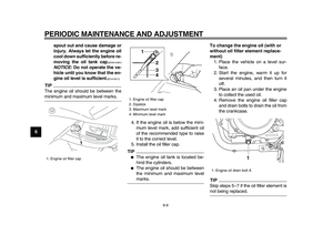
4. Remove the engine oil filler cap
and drain bolts to drain the oil from
the crankcase.
TIP
Skip steps 5–7 if the oil filter element is
not being replaced.
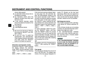
1. Engine oil filler cap
1
1. Engine oil filler cap
2. Dipstick
3. Maximum level mark
4. Minimum level mark
1
2
3
4
1. Engine oil drain bolt A
1
Page 55 of 94

PERIODIC MAINTENANCE AND ADJUSTMENT
6-10
2
3
4
5
67
8
9
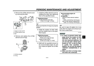
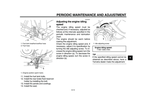
5. Remove the oil filter element cover
by removing the bolts.
6. Remove and replace the oil filter
element and O-rings.7. Install the oil filter element cover by
installing the bolts, then tightening
them to the specified torque.
TIP
Make sure that the O-rings are properly
seated.
8. Install the engine oil drain bolts,
and then tighten them to the spec-
ified torques.
9. Refill with the specified amount of
the recommended engine oil, and
then install and tighten the oil filler
cap.
TIP
Be sure to wipe off spilled oil on any
parts after the engine and exhaust sys-
tem have cooled down.
NOTICE
ECA11620
●
In order to prevent clutch slip-
page (since the engine oil also
lubricates the clutch), do not
mix any chemical additives. Do
not use oils with a diesel speci-
fication of “CD” or oils of a high-
er quality than specified. In
addition, do not use oils labeled
“ENERGY CONSERVING II” or
higher.
●
Make sure that no foreign mate-
rial enters the crankcase.
1. Engine oil drain bolt B
2. Oil filter element cover
3. Bolt
1. Oil filter element
2. O-ring
12
2
3
1
2
Tightening torque:
Oil filter element cover bolt:
10 Nm (1.0 m·kgf, 7.2 ft·lbf)
Tightening torques:
Engine oil drain bolt A:
35 Nm (3.5 m·kgf, 25 ft·lbf)
Engine oil drain bolt B:
30 Nm (3.0 m·kgf, 21.7 ft·lbf)
Recommended engine oil:
See page 8-1.
Oil quantity:
Without oil filter element replace-
ment:
3.80 L (4.02 US qt, 3.34 Imp.qt)
With oil filter element replacement:
3.90 L (4.12 US qt, 3.43 Imp.qt)
Page 56 of 94

PERIODIC MAINTENANCE AND ADJUSTMENT
6-11
1
2
3
4
5
6
7
8
9
10. Start the engine, and then let it idle
for several minutes while checking
it for oil leakage. If oil is leaking, im-
mediately turn the engine off and
check for the cause.
11. Turn the engine off, and then
check the oil level and correct it if
necessary.
EAU20070
Coolant
The coolant level should be checked
before each ride. In addition, the cool-
ant must be changed at the intervals
specified in the periodic maintenance
and lubrication chart.
EAU38583
To check the coolant level
1. Place the vehicle on a level sur-
face and hold it in an upright posi-
tion.
TIP
●
The coolant level must be checked
on a cold engine since the level
varies with engine temperature.
●
Make sure that the vehicle is posi-
tioned straight up when checking
the coolant level. A slight tilt to the
side can result in a false reading.
2. Check the coolant level in the cool-
ant reservoir.
TIP
The coolant should be between the
minimum and maximum level marks.
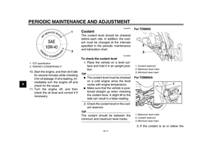
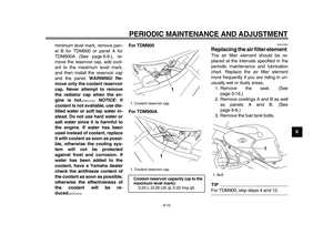
For TDM900
For TDM900A
3. If the coolant is at or below the
1. “CD” specification
2. “ENERGY CONSERVING II”
1
2
1. Coolant reservoir
2. Maximum level mark
3. Minimum level mark
1. Maximum level mark
2. Coolant reservoir
3. Minimum level mark
1 2
33 1
2