Page 25 of 94
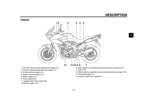
INSTRUMENT AND CONTROL FUNCTIONS
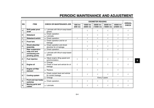
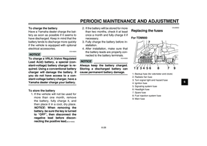
3-9
2
34
5
6
7
8
9
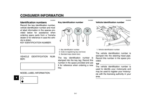
EAU12331
Anti-theft alarm (optional)
This model can be equipped with an
optional anti-theft alarm by a Yamaha
dealer. Contact a Yamaha dealer for
more information.
EAU12347
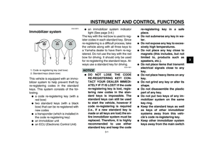
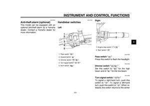
Handlebar switches
LeftRight
EAU12350
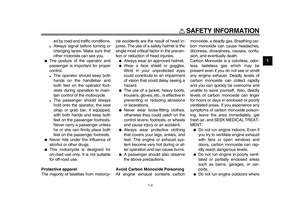
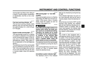
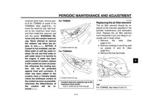
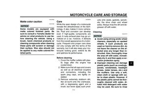
Pass switch “ ”
Press this switch to flash the headlight.
EAU12400
Dimmer switch “ / ”
Set this switch to “ ” for the high
beam and to “ ” for the low beam.
EAU12460
Turn signal switch “ / ”
To signal a right-hand turn, push this
switch to “ ”. To signal a left-hand
turn, push this switch to “ ”. When re-
leased, the switch returns to the center
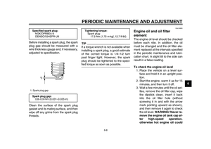
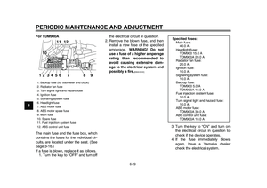
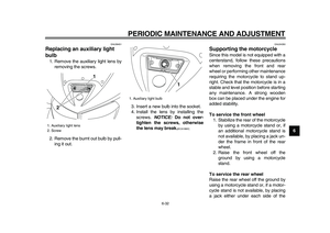
1. Pass switch “ ”
2. Hazard switch “ ”
3. Dimmer switch “ / ”
4. Turn signal switch “ / ”
5. Horn switch “ ”
1
2
3
4
5
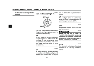
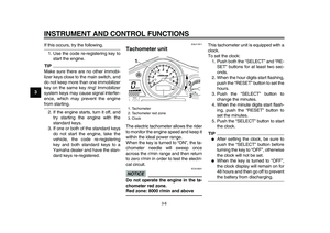
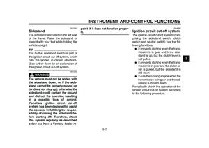
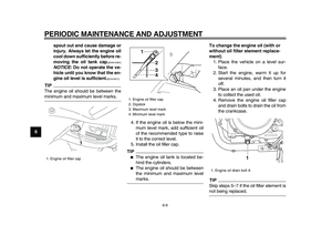
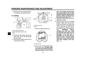
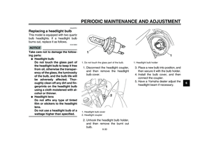
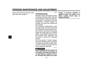
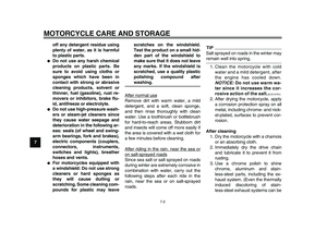
1. Engine stop switch “ / ”
2. Start switch “ ”
1
2
Page 26 of 94

INSTRUMENT AND CONTROL FUNCTIONS
3-10
1
2
3
4
5
6
7
8
9
position. To cancel the turn signal
lights, push the switch in after it has re-
turned to the center position.
EAU12500
Horn switch “ ”
Press this switch to sound the horn.
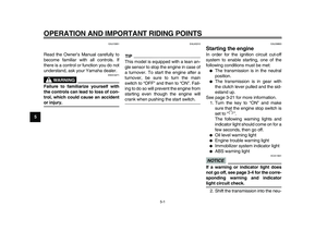
EAU12660
Engine stop switch “ / ”
Set this switch to “ ” before starting
the engine. Set this switch to “ ” to
stop the engine in case of an emergen-
cy, such as when the vehicle overturns
or when the throttle cable is stuck.
EAU12711
Start switch “ ”
Push this switch to crank the engine
with the starter. See page 5-1 for start-
ing instructions prior to starting the en-
gine.
EAU44710
The engine trouble warning light and
ABS warning light (ABS model only)
will come on when the key is turned to
“ON” and the start switch is pushed, butthis does not indicate a malfunction.
EAU12733
Hazard switch “ ”
With the key in the “ON” or “ ” posi-
tion, use this switch to turn on the haz-
ard lights (simultaneous flashing of all
turn signal lights).
The hazard lights are used in case of
an emergency or to warn other drivers
when your vehicle is stopped where it
might be a traffic hazard.
NOTICE
ECA10061
Do not use the hazard lights for an
extended length of time with the en-
gine not running, otherwise the bat-
tery may discharge.
EAU12820
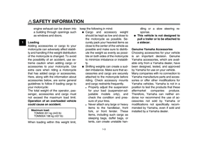
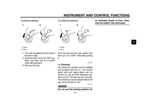
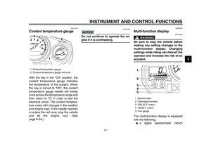
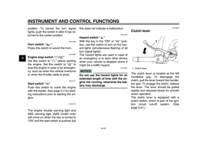
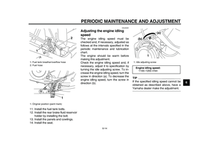
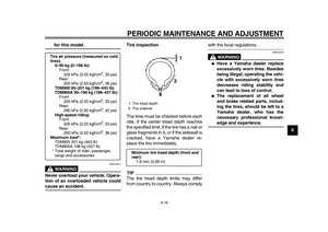
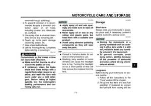
Clutch lever
The clutch lever is located at the left
handlebar grip. To disengage the
clutch, pull the lever toward the handle-
bar grip. To engage the clutch, release
the lever. The lever should be pulled
rapidly and released slowly for smooth
clutch operation.
The clutch lever is equipped with a
clutch switch, which is part of the igni-
tion circuit cut-off system. (See
page 3-21.)
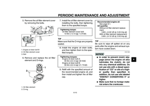
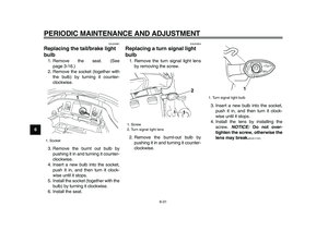
1. Clutch lever
1
Page 27 of 94
INSTRUMENT AND CONTROL FUNCTIONS
3-11
2
34
5
6
7
8
9
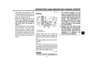
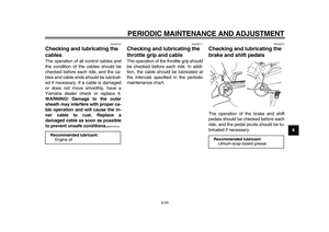
EAU12870
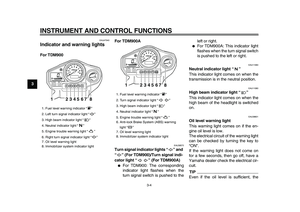
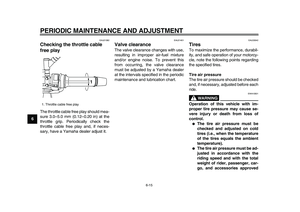
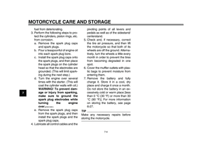
Shift pedal
The shift pedal is located on the left
side of the engine and is used in com-
bination with the clutch lever when
shifting the gears of the 6-speed con-
stant-mesh transmission equipped on
this motorcycle.
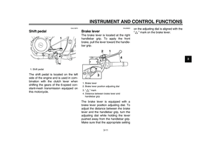
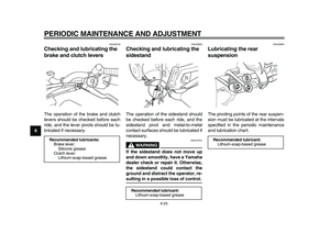
EAU26823
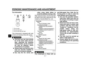
Brake lever
The brake lever is located at the right
handlebar grip. To apply the front
brake, pull the lever toward the handle-
bar grip.
The brake lever is equipped with a
brake lever position adjusting dial. To
adjust the distance between the brake
lever and the handlebar grip, turn the
adjusting dial while holding the lever
pushed away from the handlebar grip.
Make sure that the appropriate settingon the adjusting dial is aligned with the
“” mark on the brake lever.
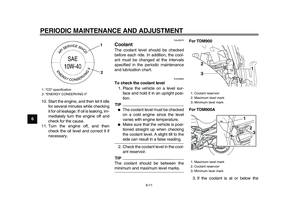
1. Shift pedal
1
1. Brake lever
2. Brake lever position adjusting dial
3. “ ” mark
4. Distance between brake lever and
handlebar grip
1 2
4
3
Page 28 of 94

INSTRUMENT AND CONTROL FUNCTIONS
3-12
1
2
3
4
5
6
7
8
9
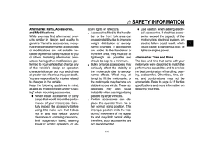
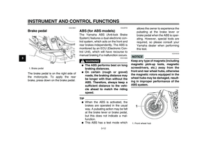
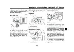
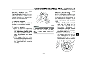
EAU12941
Brake pedal
The brake pedal is on the right side of
the motorcycle. To apply the rear
brake, press down on the brake pedal.
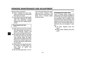
EAU26793
ABS (for ABS models)
The Yamaha ABS (Anti-lock Brake
System) features a dual electronic con-
trol system, which acts on the front and
rear brakes independently. The ABS is
monitored by an ECU (Electronic Con-
trol Unit), which will have recourse to
manual braking if a malfunction occurs.
WARNING
EWA10090
●
The ABS performs best on long
braking distances.
●
On certain (rough or gravel)
roads, the braking distance may
be longer with than without the
ABS. Therefore, always keep a
sufficient distance to the vehi-
cle ahead to match the riding
speed.
TIP
●
When the ABS is activated, the
brakes are operated in the usual
way. A pulsating action may be felt
at the brake lever or brake pedal,
but this does not indicate a mal-
function.
●
This ABS has a test mode whichallows the owner to experience the
pulsating at the brake lever or
brake pedal when the ABS is oper-
ating. However, special tools are
required, so please consult your
Yamaha dealer when performing
this test.
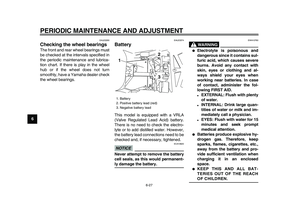
NOTICE
ECA16120
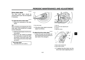
Keep any type of magnets (including
magnetic pick-up tools, magnetic
screwdrivers, etc.) away from the
front and rear wheel hubs, otherwise
the magnetic rotors equipped in the
wheel hubs may be damaged, result-
ing in improper performance of the
ABS system.
1. Brake pedal
1
1. Front wheel hub
1
Page 29 of 94
INSTRUMENT AND CONTROL FUNCTIONS
3-13
2
34
5
6
7
8
9
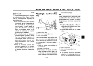
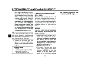
EAU13091
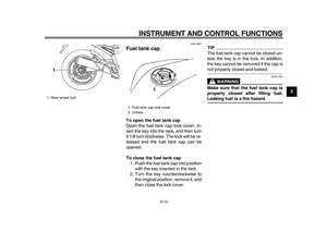
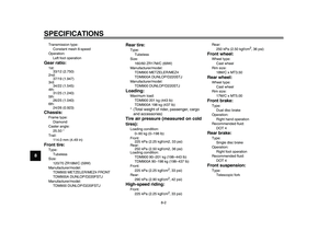
Fuel tank cap
To open the fuel tank cap
Open the fuel tank cap lock cover, in-
sert the key into the lock, and then turn
it 1/8 turn clockwise. The lock will be re-
leased and the fuel tank cap can be
opened.
To close the fuel tank cap
1. Push the fuel tank cap into position
with the key inserted in the lock.
2. Turn the key counterclockwise to
the original position, remove it, and
then close the lock cover.
TIP
The fuel tank cap cannot be closed un-
less the key is in the lock. In addition,
the key cannot be removed if the cap is
not properly closed and locked.
WARNING
EWA11091
Make sure that the fuel tank cap is
properly closed after filling fuel.
Leaking fuel is a fire hazard.
1. Rear wheel hub
1
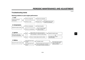
1. Fuel tank cap lock cover
2. Unlock.
1
2
Page 30 of 94

INSTRUMENT AND CONTROL FUNCTIONS
3-14
1
2
3
4
5
6
7
8
9
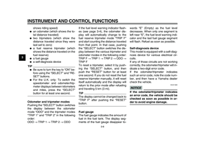
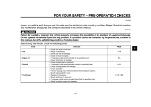
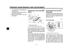
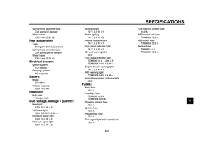
EAU13212
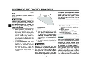
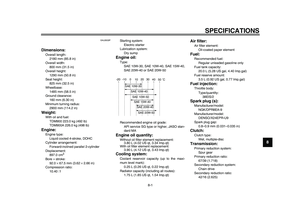
Fuel
Make sure there is sufficient gasoline in
the tank.
WARNING
EWA10881
Gasoline and gasoline vapors are
extremely flammable. To avoid fires
and explosions and to reduce the
risk of injury when refueling, follow
these instructions.
1. Before refueling, turn off the en-
gine and be sure that no one is sit-
ting on the vehicle. Never refuel
while smoking, or while in the vi-
cinity of sparks, open flames, or
other sources of ignition such as
the pilot lights of water heaters and
clothes dryers.
2. Do not overfill the fuel tank. Stop
filling when the fuel reaches the
bottom of the filler tube. Because
fuel expands when it heats up,
heat from the engine or the sun
can cause fuel to spill out of the
fuel tank.3. Wipe up any spilled fuel immedi-
ately.
NOTICE:
Immediately wipe
off spilled fuel with a clean, dry,
soft cloth, since fuel may deteri-
orate painted surfaces or plastic
parts.
[ECA10071]
4. Be sure to securely close the fuel
tank cap.
WARNING
EWA15151
Gasoline is poisonous and can
cause injury or death. Handle gaso-
line with care. Never siphon gaso-
line by mouth. If you should swallow
some gasoline or inhale a lot of gas-
oline vapor, or get some gasoline inyour eyes, see your doctor immedi-
ately. If gasoline spills on your skin,
wash with soap and water. If gaso-
line spills on your clothing, change
your clothes.
EAU13320
NOTICE
ECA11400
Use only unleaded gasoline. The use
of leaded gasoline will cause severe
damage to internal engine parts,
such as the valves and piston rings,
as well as to the exhaust system.
Your Yamaha engine has been de-
signed to use regular unleaded gaso-
line with a research octane number of
91 or higher. If knocking (or pinging) oc-
curs, use a gasoline of a different brand
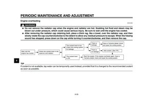
1. Fuel tank filler tube
2. Fuel level
1 2
Recommended fuel:
REGULAR UNLEADED GASOLINE
ONLY
Fuel tank capacity:
20.0 L (5.28 US gal, 4.40 Imp.gal)
Fuel reserve amount:
3.5 L (0.92 US gal, 0.77 Imp.gal)
Page 31 of 94

INSTRUMENT AND CONTROL FUNCTIONS
3-15
2
34
5
6
7
8
9
or premium unleaded fuel. Use of un-
leaded fuel will extend spark plug life
and reduce maintenance costs.
EAU13412
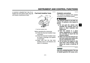
Fuel tank breather hose
Before operating the motorcycle:
●
Check the fuel tank breather hose
connection.
●
Check the fuel tank breather hose
for cracks or damage, and replace
it if damaged.
●
Make sure that the fuel tank
breather hose is not blocked, and
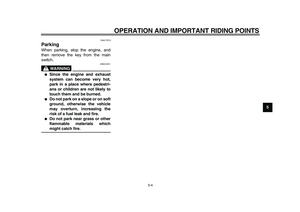
clean it if necessary.
EAU13445
Catalytic converters
This vehicle is equipped with catalytic
converters in the exhaust system.
WARNING
EWA10862
The exhaust system is hot after op-
eration. To prevent a fire hazard or
burns:
●
Do not park the vehicle near
possible fire hazards such as
grass or other materials that
easily burn.
●
Park the vehicle in a place
where pedestrians or children
are not likely to touch the hot
exhaust system.
●
Make sure that the exhaust sys-
tem has cooled down before do-
ing any maintenance work.
●
Do not allow the engine to idle
more than a few minutes. Long
idling can cause a build-up of
heat.
NOTICE
ECA10701
Use only unleaded gasoline. The use
of leaded gasoline will cause unre-
1. Fuel tank breather hose
1
Page 32 of 94
INSTRUMENT AND CONTROL FUNCTIONS
3-16
1
2
3
4
5
6
7
8
9pairable damage to the catalytic
converter.
EAU13861
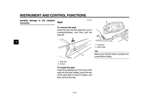
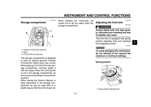
Seat
To remove the seat
Insert the key into the seat lock, turn it
counterclockwise, and then pull the
seat off.
To install the seat
Insert the projections on the front of the
seat into the seat holders, push the rear
of the seat down to lock it in place, and
then remove the key.
TIP
Make sure that the seat is properly se-
cured before riding.
1. Seat lock
2. Unlock.
1
2
1. Projection
2. Seat holder
1
2


This model can be equipped with an
optional anti-theft alarm by a Yamaha
dealer. Contact a Yamaha deal")


