Page 89 of 108
Maintenance and care
82
*1 This operation should be performed after every use.
*2 This operation should be performed before long-term storage.
BatteryCheck, charge 89
Rubber couplingCheck—
Engine mountCheck—
Nuts and boltsCheck—
Air filter elementCheck 83
Engine oilReplace
50 hours or 12 months83
Oil filterReplace 83
Valve clearanceCheck, adjust— Item OperationInitial Thereafter every
Page 10
hours50
hours100
hours100
hours200
hours
6
months12
months12
months24
months
UF1W71E0.book Page 82 Tuesday, June 24, 2008 11:46 AM
Page 90 of 108

Maintenance and care
83
EJU34212Checking the fuel system
WARNING
EWJ00381
Leaking fuel can result in fire or explosion.
�Check for fuel leakage regularly.
�If any fuel leakage is found, the fuel sys-
tem must be repaired by a qualified me-
chanic. Improper repairs can make the
watercraft unsafe to operate.
Check the fuel system for leaks, cracks, and
malfunctions. If any problem is found, consult
a Yamaha dealer.
Check:
�Fuel tank filler cap and seal for damage
�Fuel in fuel tank for water and dirt
�Fuel tank for damage, cracks, and leakage
�Fuel hoses and joints for damage, cracks,
and leakage
�Air bleeding passages for leakageEJU34230Fuel tank
Check the fuel tank for leakage and for water
in the tank. If water is found in the fuel system,
or if the fuel tank needs to be cleaned, have a
Yamaha dealer service the watercraft.
EJU36951Engine oil and oil filter
WARNING
EWJ00340
Engine oil is extremely hot immediately af-
ter the engine is turned off. Coming in con-
tact with or getting any engine oil on your
clothes could result in burns.
NOTICE
ECJ00991
Do not run the engine with too much or not
enough oil in the engine, otherwise the en-
gine could be damaged.
It is recommended to have a Yamaha dealer
change the engine oil. However, if you choose
to change the oil on your own, consult a
Yamaha dealer.
EJU34311Air filter element
Have a Yamaha dealer check the air filter ele-
ment at the intervals specified in the periodic
maintenance chart.
EJU34321Checking the jet thrust nozzle angle
Check the handlebars and jet thrust nozzle for
smooth operation.
Turn the handlebars as far as possible to the
right and left and check that the difference of
distances A and B between the jet thrust noz-
zle and the nozzle is within specification.1Fuel tank
1
Recommended engine oil:
SAE 10W-30, 10W-40, 20W-40, 20W-
50
Oil grade:
API SE,SF,SG,SH,SJ,SL
Oil quantity:
With oil filter replacement:
3.1 L (3.28 US qt, 2.73 Imp.qt)
Without oil filter replacement:
3.0 L (3.17 US qt, 2.64 Imp.qt)
Total amount:
4.3 L (4.55 US qt, 3.78 Imp.qt)
UF1W71E0.book Page 83 Tuesday, June 24, 2008 11:46 AM
Page 91 of 108

Maintenance and care
84
If the steering is stiff or misadjusted, have a
Yamaha dealer service it.
EJU36590Checking the shift cable
Place the shift lever in the reverse position.
Make sure that the reverse gate makes con-
tact with the stopper.If the reverse gate does not make contact with
the stopper, have a Yamaha dealer service it.
EJU37030Checking and adjusting the throttle
cable
Face the handlebars straight ahead, and then
check that the throttle cable moves back to
the set position smoothly and that the throttle
lever free play is within specification.
Squeeze and release the throttle lever. If the
throttle lever does not return smoothly, have a
Yamaha dealer service it.
If the specified throttle lever free play cannot
be obtained as described below, have a
Yamaha dealer make the adjustment.
FX SHO
(1) Remove the eight screws, and then re-
move the front handlebar cover.
(2) Slide the rubber cover away from the ad-
juster, and then loosen the locknut. Difference of A and B:
Maximum 5 mm (0.20 in)
1Stopper
1Front handlebar cover
UF1W71E0.book Page 84 Tuesday, June 24, 2008 11:46 AM
Page 92 of 108
 Make sure that the handlebars are facing
straight ahead, and then adjust the free
play by turning the adjuster.
(4) Hold the adjuster with one wrench while
tightening the l")
Maintenance and care
85
(3) Make sure that the handlebars are facing
straight ahead, and then adjust the free
play by turning the adjuster.
(4) Hold the adjuster with one wrench while
tightening the locknut with another
wrench. Slide the rubber cover to its orig-
inal position.
(5) Install the front handlebar cover, and then
install the eight screws.
FX Cruiser SHO
(1) Remove the ten screws, and then re-
move the front and rear handlebar cov-
ers.(2) Slide the rubber cover away from the ad-
juster, and then loosen the locknut.
(3) Make sure that the handlebars are facing
straight ahead, and then adjust the free
play by turning the adjuster.
(4) Hold the adjuster with one wrench while
tightening the locknut with another
wrench. Slide the rubber cover to its orig-
inal position.
1Rubber cover
2Locknut
3Adjuster
4Throttle lever free play
Throttle lever free play:
2.0–5.0 mm (0.08–0.20 in)
1Front handlebar cover
2Rear handlebar cover
1Rubber cover
2Locknut
3Adjuster
4Throttle lever free play
Throttle lever free play:
2.0–5.0 mm (0.08–0.20 in)
UF1W71E0.book Page 85 Tuesday, June 24, 2008 11:46 AM
Page 93 of 108
 Install the front and rear handlebar cov-
ers as shown in the illustration, and then
install the ten screws.
EJU37041Cleaning and adjusting the spark
plugs
WARNING
EWJ003")
Maintenance and care
86
(5) Install the front and rear handlebar cov-
ers as shown in the illustration, and then
install the ten screws.
EJU37041Cleaning and adjusting the spark
plugs
WARNING
EWJ00350
Be careful not to damage the insulator
when removing or installing a spark plug.
A damaged insulator could allow sparks to
escape, which could result in a fire or ex-
plosion.
The spark plug is an important engine compo-
nent and is easy to inspect. The condition of
the spark plug can indicate something about
the condition of the engine. For example, if
one spark plug has a distinctly different color,
the engine could require servicing. Do not at-
tempt to diagnose any problems yourself.
Have a Yamaha dealer service the watercraft.Remove and inspect the spark plugs periodi-
cally; heat and deposits will cause the spark
plugs to slowly break down and erode. If elec-
trode erosion becomes excessive, or if carbon
and other deposits are excessive, replace the
spark plug with the specified plug.
To remove a spark plug:
(1) Remove the seats. (See page 25 for seat
removal and installation procedures.)
(2) Remove the engine cover screws, and
then remove the engine cover.
(3) Remove the spark plug cap bolts, and
then remove the spark plug cap.
NOTICE: Do not use any tools to re-
move or install the spark plug cap,
otherwise the ignition coil coupler
could be damaged. The spark plug
cap may be difficult to remove be-
cause the rubber seal on the end of
the cap fits tightly. To remove the
spark plug cap, simply twist it back
and forth while pulling it up; to install
it, twist it back and forth while pushing
it down.
[ECJ00211]
Specified spark plug:
LFR6A
1Engine cover screw
2Engine cover
1 2
UF1W71E0.book Page 86 Tuesday, June 24, 2008 11:46 AM
Page 94 of 108
 Remove the spark plug.
Measure th")
Maintenance and care
87
TIP:
If removing the spark plug cap nearest the
stern, remove the plastic tie that is securing
the wiring harness before removing the cap.
(4) Remove the spark plug.
Measure the spark plug gap with a wire
thickness gauge. Replace the spark plug
or adjust the gap to specification if neces-
sary.
To install a spark plug:
(1) Clean the gasket surface.
(2) Wipe any dirt from the threads of the
spark plug.(3) Install the spark plug, and then tighten it
to the specified torque.
TIP:
If a torque wrench is not available when you
are installing a spark plug, a good estimate of
the correct torque is 1/4 turn to 1/2 turn past
finger tight using the spark plug wrench in-
cluded in the tool kit. Have the spark plug ad-
justed to the correct torque with a torque
wrench as soon as possible.
(4) Wipe off any water on the spark plug or
inside the spark plug cap, and then install
the cap. Push the spark plug cap down
until it is securely installed, and then in-
stall the spark plug cap bolts and tighten
them to the specified torque.
If the spark plug cap nearest the stern
was removed, secure the wiring harness
by installing the plastic tie after installing
the cap.
(5) Install the engine cover and engine cover
screws, and then install the seats.
EJU36970Lubrication points
To keep moving parts sliding or rotating
smoothly, coat them with water-resistant
grease.
�Throttle cable (handlebar end)
Loosen the adjuster and disconnect the
outer cable from the bracket. Spray a rust
inhibitor into the outer cable. Connect the
1Spark plug cap bolt
2Spark plug cap
3Plastic tie
1Spark plug gap
Spark plug gap:
0.8–0.9 mm (0.031–0.035 in)
1
2
3
Spark plug tightening torque:
24.5 Nm (2.50 kgf-m, 18.1 ft-lb)
Spark plug cap bolt tightening torque:
7.6 Nm (0.77 kgf-m, 5.6 ft-lb)
Recommended water-resistant grease:
Yamaha Marine Grease/Yamaha
Grease A
UF1W71E0.book Page 87 Tuesday, June 24, 2008 11:46 AM
Page 95 of 108
Maintenance and care
88
outer cable, and then adjust the throttle ca-
ble free play. (See page 84 for adjustment
procedures.)
�Steering cable (handlebar end)
�Steering cable (jet thrust nozzle end)
�QSTS rod (jet thrust nozzle end)
�Shift cable (shift lever end)
�Shift cable (reverse gate end)
�Intermediate housing
Fill the intermediate housing with water-re-
sistant grease through the grease nipple
using a grease gun.
1Adjuster
UF1W71E0.book Page 88 Tuesday, June 24, 2008 11:46 AM
Page 96 of 108
 and positive
(+) battery leads are tightened securely.
WARNING
EW")
Maintenance and care
89
EJU34452Checking the battery
Check the level of the battery electrolyte and
make sure that the negative (–) and positive
(+) battery leads are tightened securely.
WARNING
EWJ00791
Battery electrolyte is poisonous and dan-
gerous, causing severe burns, etc. Elec-
trolyte contains sulfuric acid. Avoid
contact with skin, eyes, or clothing.
Antidotes
External: Flush with water.
Internal: Drink large quantities of water or
milk. Follow with milk of magnesia, beaten
egg, or vegetable oil. Call a physician im-
mediately.
Eyes: Flush with water for 15 minutes and
get prompt medical attention.
Batteries produce explosive gases. Keep
sparks, flames, cigarettes, etc., well away.
If using or charging the battery in an en-
closed space, make sure that it is well ven-tilated. Always shield your eyes when
working near batteries.
Keep out of the reach of children.
To remove the battery:
Disconnect the negative (–) battery lead first,
then the positive (+) battery lead and breather
hose, and then remove the battery from the
watercraft.
To replenish the battery:
(1) Make sure that the electrolyte level is be-
tween the maximum and minimum level
marks.
(2) If the electrolyte level is low, add distilled
water to raise it to the specified level.
NOTICE: Use only distilled water for
replenishing the battery, otherwise
battery life could be shortened.
[ECJ00241]
To recharge the battery:
NOTICE
ECJ00250
Do not attempt to charge a battery hastily.
Battery life could be shortened.
It is recommended to have a Yamaha dealer
charge the battery. If you charge the battery
yourself, be sure to read and follow the in-
structions provided with the battery tester and
charger you use. Grease quantity:
Initial 10 hours or 1 month:
33.0–35.0 cm³ (1.12–1.18 US oz,
1.16–1.23 Imp.oz)
Every 100 hours or 12 months:
6.0–8.0 cm³ (0.20–0.27 US oz,
0.21–0.28 Imp.oz)
1Grease nipple
1
1Maximum level mark
2Minimum level mark
UF1W71E0.book Page 89 Tuesday, June 24, 2008 11:46 AM
 1
1 2
2 3
3 4
4 5
5 6
6 7
7 8
8 9
9 10
10 11
11 12
12 13
13 14
14 15
15 16
16 17
17 18
18 19
19 20
20 21
21 22
22 23
23 24
24 25
25 26
26 27
27 28
28 29
29 30
30 31
31 32
32 33
33 34
34 35
35 36
36 37
37 38
38 39
39 40
40 41
41 42
42 43
43 44
44 45
45 46
46 47
47 48
48 49
49 50
50 51
51 52
52 53
53 54
54 55
55 56
56 57
57 58
58 59
59 60
60 61
61 62
62 63
63 64
64 65
65 66
66 67
67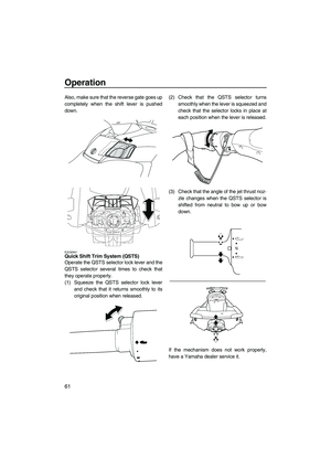 68
68 69
69 70
70 71
71 72
72 73
73 74
74 75
75 76
76 77
77 78
78 79
79 80
80 81
81 82
82 83
83 84
84 85
85 86
86 87
87 88
88 89
89 90
90 91
91 92
92 93
93 94
94 95
95 96
96 97
97 98
98 99
99 100
100 101
101 102
102 103
103 104
104 105
105 106
106 107
107
