Page 17 of 68
 as the fuel level
decreases. When the")
INSTRUMENT AND CONTROL FUNCTIONS
3-4
3
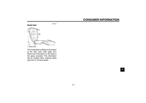
EAU12140
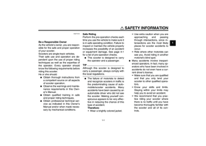
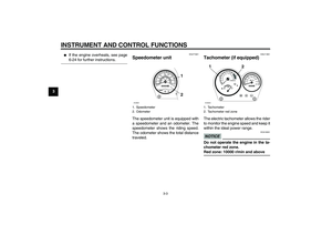
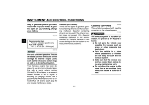
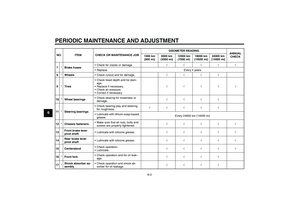
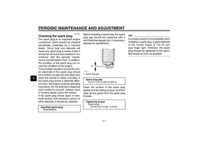
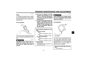
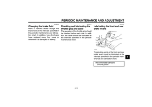
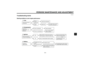
Fuel gauge The fuel gauge indicates the amount of
fuel in the fuel tank. The needle moves
towards “E” (Empty) as the fuel level
decreases. When the needle reaches
“E”, refuel as soon as possible.TIPDo not allow the fuel tank to empty itselfcompletely.
EAU12347
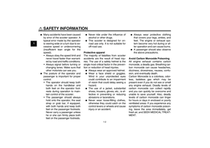
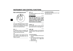
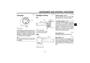
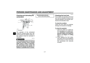
Handlebar switches Left
Right
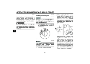
EAU12400
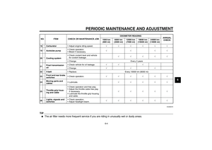
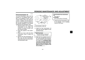
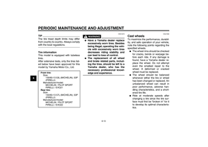
Dimmer switch“/”
Set this switch to“” for the high
beam and to“” for the low beam.
EAU12460
Turn signal switch“/”
To signal a right-hand turn, push this
switch to“”. To signal a left-hand
turn, push this switch to“”. When re-
leased, the switch returns to the center
position. To cancel the turn signal
lights, push the switch in after it has re-
turned to the center position.
EAU12500
Horn switch“”
Press this switch to sound the horn.
EAUM1132
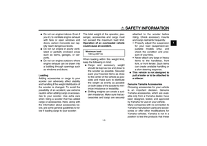
Start switch“”
Push this switch while applying the
front or rear brake to crank the engine
with the starter. See page 5-1 for start-
ing instructions prior to starting the en-
gine.
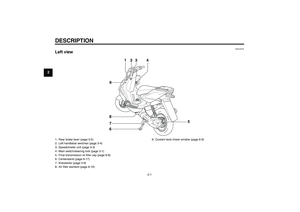
1. Fuel gauge
E1/2
F
1
ZAUM0257
1. Horn switch“”
2. Turn signal switch“/”
3. Dimmer switch“/”
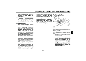
1. Start switch“”
U3C6E1E0.book Page 4 Friday, August 8, 2008 10:09 AM
Page 18 of 68
INSTRUMENT AND CONTROL FUNCTIONS
3-5
3
EAU12900
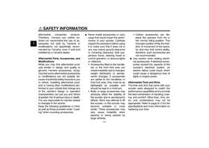
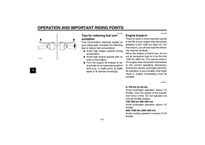
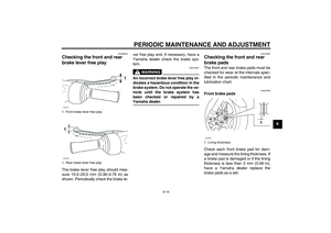
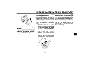
Front brake lever The front brake lever is located on the
right handlebar grip. To apply the front
brake, pull this lever toward the handle-
bar grip.
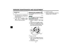
EAU12950
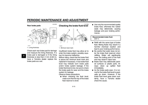
Rear brake lever The rear brake lever is located on the
left handlebar grip. To apply the rear
brake, pull this lever toward the handle-
bar grip.
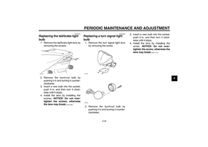
EAUM2081
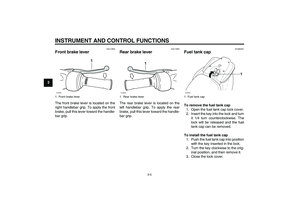
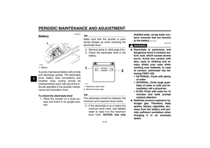
Fuel tank cap To remove the fuel tank cap
1. Open the fuel tank cap lock cover.
2. Insert the key into the lock and turn
it 1/4 turn counterclockwise. The
lock will be released and the fuel
tank cap can be removed.
To install the fuel tank cap
1. Push the fuel tank cap into position
with the key inserted in the lock.
2. Turn the key clockwise to the orig-
inal position, and then remove it.
3. Close the lock cover.
1. Front brake lever
1
ZAUM0084
1. Rear brake lever
1
ZAUM0085
1. Fuel tank cap
1
ZAUM0262
U3C6E1E0.book Page 5 Friday, August 8, 2008 10:09 AM
Page 19 of 68

INSTRUMENT AND CONTROL FUNCTIONS
3-6
3
TIPThe fuel tank cap cannot be installed
unless the key is in the lock. In addition,
the key cannot be removed if the cap isnot properly installed and locked.
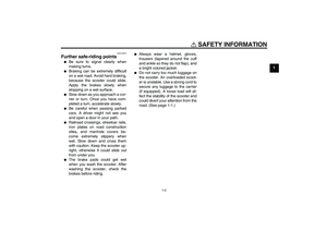
WARNING
EWA11141
Make sure that the fuel tank cap is
properly installed before riding.Leaking fuel is a fire hazard.
EAU13212
Fuel Make sure there is sufficient gasoline in
the tank.
WARNING
EWA10881
Gasoline and gasoline vapors are
extremely flammable. To avoid fires
and explosions and to reduce the
risk of injury when refueling, followthese instructions.
1. Before refueling, turn off the en-
gine and be sure that no one is sit-
ting on the vehicle. Never refuel
while smoking, or while in the vi-
cinity of sparks, open flames, or
other sources of ignition such as
the pilot lights of water heaters and
clothes dryers.
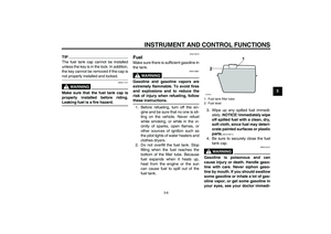
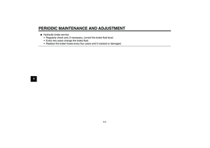
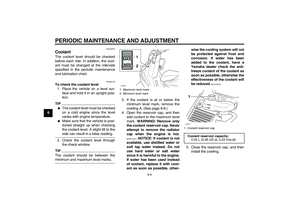
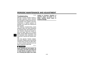
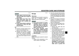
2. Do not overfill the fuel tank. Stop
filling when the fuel reaches the
bottom of the filler tube. Because
fuel expands when it heats up,
heat from the engine or the sun
can cause fuel to spill out of the
fuel tank.3. Wipe up any spilled fuel immedi-
ately. NOTICE: Immediately wipe
off spilled fuel with a clean, dry,
soft cloth, since fuel may deteri-
orate painted surfaces or plastic
parts.
[ECA10071]
4. Be sure to securely close the fuel
tank cap.
WARNING
EWA15151
Gasoline is poisonous and can
cause injury or death. Handle gaso-
line with care. Never siphon gaso-
line by mouth. If you should swallow
some gasoline or inhale a lot of gas-
oline vapor, or get some gasoline in
your eyes, see your doctor immedi-1. Fuel tank filler tube
2. Fuel level
1
2
ZAUM0020
U3C6E1E0.book Page 6 Friday, August 8, 2008 10:09 AM
Page 20 of 68

INSTRUMENT AND CONTROL FUNCTIONS
3-7
3ately. If gasoline spills on your skin,
wash with soap and water. If gaso-
line spills on your clothing, change
your clothes.
EAU41272
NOTICE
ECA11400
Use only unleaded gasoline. The use
of leaded gasoline will cause severe
damage to internal engine parts,
such as the valves and piston rings,as well as to the exhaust system.
Your Yamaha engine has been de-
signed to use premium unleaded gaso-
line with a pump octane number
[(R+M)/2] of 91 or higher, or a research
octane number of 95 or higher. If
knocking (or pinging) occurs, use a
gasoline of a different brand. Use of un-
leaded fuel will extend spark plug life
and reduce maintenance costs.Gasohol (for Canada)
There are two types of gasohol: gaso-
hol containing ethanol and that contain-
ing methanol. Gasohol containing
ethanol can be used if the ethanol con-
tent does not exceed 10%. Gasohol
containing methanol is not recom-
mended by Yamaha because it can
cause damage to the fuel system or ve-
hicle performance problems.
EAU13445
Catalytic converters This vehicle is equipped with catalytic
converters in the exhaust system.
WARNING
EWA10862
The exhaust system is hot after op-
eration. To prevent a fire hazard or
burns:�
Do not park the vehicle near
possible fire hazards such as
grass or other materials that
easily burn.
�
Park the vehicle in a place
where pedestrians or children
are not likely to touch the hot
exhaust system.
�
Make sure that the exhaust sys-
tem has cooled down before do-
ing any maintenance work.
�
Do not allow the engine to idle
more than a few minutes. Long
idling can cause a build-up ofheat.
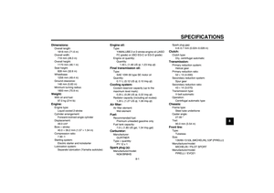
Recommended fuel:
Premium unleaded gasoline only
Fuel tank capacity:
7.0 L (1.85 US gal, 1.54 Imp.gal)
U3C6E1E0.book Page 7 Friday, August 8, 2008 10:09 AM
Page 21 of 68
INSTRUMENT AND CONTROL FUNCTIONS
3-8
3
NOTICE
ECA10701
Use only unleaded gasoline. The use
of leaded gasoline will cause unre-
pairable damage to the catalyticconverter.
EAUM2500
2-stroke engine oil Make sure that there is sufficient 2-
stroke engine oil in the oil tank. If nec-
essary, add the recommended 2-stroke
engine oil as follows.
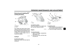
1. Open the storage compartment.
(See page 3-10.)
2. Remove the engine oil tank cap by
pulling it off.
3. Fill the oil tank with the recom-
mended 2-stroke engine oil, and
then install the tank cap by push-
ing it into the filler hole.
TIPMake sure that the 2-stroke engine oil
tank cap is properly installed beforeriding the vehicle.
1. Storage compartment B
2. Oil tank cap
1
2
ZAUM0263
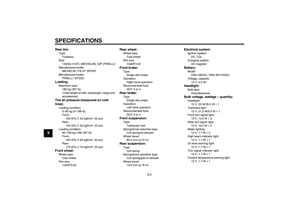
Recommended oil:
See page 8-1.
Oil quantity:
1.40 L (1.48 US qt, 1.23 Imp.qt)ZAUM0204
U3C6E1E0.book Page 8 Friday, August 8, 2008 10:09 AM
Page 22 of 68
INSTRUMENT AND CONTROL FUNCTIONS
3-9
3
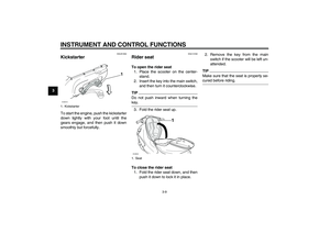
EAUS1050
Kickstarter To start the engine, push the kickstarter
down lightly with your foot until the
gears engage, and then push it down
smoothly but forcefully.
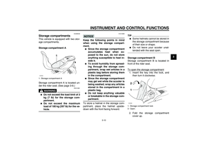
EAU14160
Rider seat To open the rider seat
1. Place the scooter on the center-
stand.
2. Insert the key into the main switch,
and then turn it counterclockwise.TIPDo not push inward when turning thekey.
3. Fold the rider seat up.
To close the rider seat
1. Fold the rider seat down, and then
push it down to lock it in place.2. Remove the key from the main
switch if the scooter will be left un-
attended.
TIPMake sure that the seat is properly se-cured before riding.
1. Kickstarter
1
ZAUM0146
1. Seat
1
ZAUM0264
U3C6E1E0.book Page 9 Friday, August 8, 2008 10:09 AM
Page 23 of 68

INSTRUMENT AND CONTROL FUNCTIONS
3-10
3
EAUM2530
Storage compartments This vehicle is equipped with two stor-
age compartments.
Storage compartment A
Storage compartment A is located un-
der the rider seat. (See page 3-9.)
WARNING
EWA10961
�
Do not exceed the load limit of 3
kg (7 lb) for the storage com-
partment.
�
Do not exceed the maximum
load of 180 kg (397 lb) for the ve-hicle.
NOTICE
ECA10080
Keep the following points in mind
when using the storage compart-
ment.�
Since the storage compartment
accumulates heat when ex-
posed to the sun, do not store
anything susceptible to heat in-
side it.
�
To avoid humidity from spread-
ing through the storage com-
partment, wrap wet articles in a
plastic bag before storing them
in the compartment.
�
Since the storage compartment
may get wet while the scooter is
being washed, wrap any articles
stored in the compartment in a
plastic bag.
�
Do not keep anything valuable
or breakable in the storage com-partment.
To store a helmet in the storage com-
partment, place the helmet upside-
down with the front facing forward.
TIP�
Some helmets cannot be stored in
the storage compartment because
of their size or shape.
�
Do not leave your scooter unat-tended with the seat open.
Storage compartment B
Storage compartment B is located in
front of the rider seat.
To open the storage compartment
1. Insert the key into the lock, and
then turn it clockwise.
2. Fold the storage compartment
cover up.
1. Storage compartment A
1
ZAUM0265
1. Storage compartment lock
2. Open.
1 2ZAUM0266
U3C6E1E0.book Page 10 Friday, August 8, 2008 10:09 AM
Page 24 of 68

INSTRUMENT AND CONTROL FUNCTIONS
3-11
3To close the storage compartment
1. Fold the storage compartment
cover down.
2. Turn the key counterclockwise,
and then remove it.
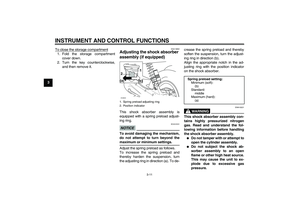
EAU14832
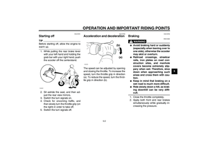
Adjusting the shock absorber
assembly (if equipped) This shock absorber assembly is
equipped with a spring preload adjust-
ing ring.NOTICE
ECA10101
To avoid damaging the mechanism,
do not attempt to turn beyond themaximum or minimum settings.
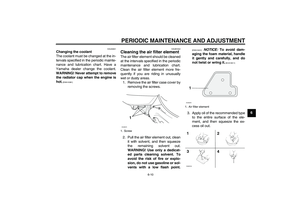
Adjust the spring preload as follows.
To increase the spring preload and
thereby harden the suspension, turn
the adjusting ring in direction (a). To de-crease the spring preload and thereby
soften the suspension, turn the adjust-
ing ring in direction (b).
Align the appropriate notch in the ad-
justing ring with the position indicator
on the shock absorber.
WARNING
EWA10221
This shock absorber assembly con-
tains highly pressurized nitrogen
gas. Read and understand the fol-
lowing information before handling
the shock absorber assembly.�
Do not tamper with or attempt to
open the cylinder assembly.
�
Do not subject the shock ab-
sorber assembly to an open
flame or other high heat source.
This may cause the unit to ex-
plode due to excessive gas
pressure.
1. Spring preload adjusting ring
2. Position indicator
(b) (a)1
2ZAUM0294
Spring preload setting:
Minimum (soft):
(b)
Standard:
middle
Maximum (hard):
(a)
U3C6E1E0.book Page 11 Friday, August 8, 2008 10:09 AM