Page 2242 of 2453
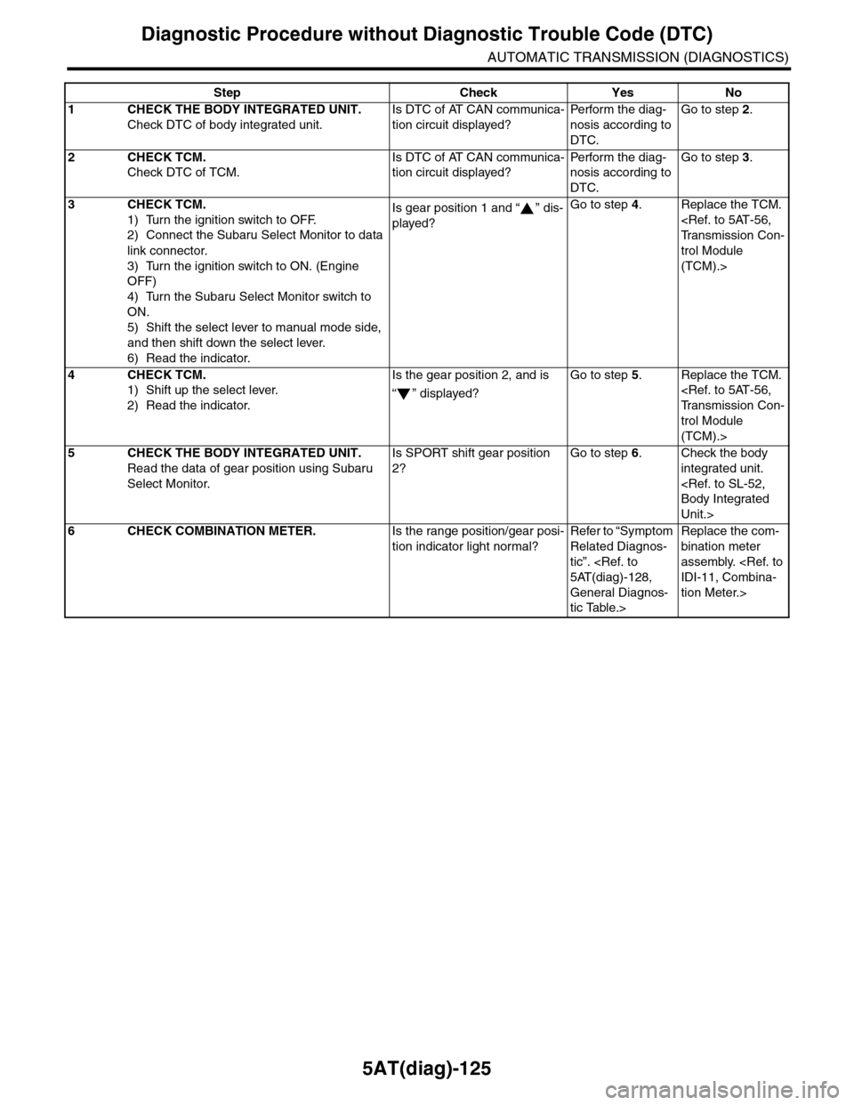
5AT(diag)-125
Diagnostic Procedure without Diagnostic Trouble Code (DTC)
AUTOMATIC TRANSMISSION (DIAGNOSTICS)
Step Check Yes No
1CHECK THE BODY INTEGRATED UNIT.
Check DTC of body integrated unit.
Is DTC of AT CAN communica-
tion circuit displayed?
Pe r for m t h e d ia g -
nosis according to
DTC.
Go to step 2.
2CHECK TCM.
Check DTC of TCM.
Is DTC of AT CAN communica-
tion circuit displayed?
Pe r for m t h e d ia g -
nosis according to
DTC.
Go to step 3.
3CHECK TCM.
1) Turn the ignition switch to OFF.
2) Connect the Subaru Select Monitor to data
link connector.
3) Turn the ignition switch to ON. (Engine
OFF)
4) Turn the Subaru Select Monitor switch to
ON.
5) Shift the select lever to manual mode side,
and then shift down the select lever.
6) Read the indicator.
Is gear position 1 and “ ” dis-
played?
Go to step 4.Replace the TCM.
Tr a n s m i s s i o n C o n -
trol Module
(TCM).>
4CHECK TCM.
1) Shift up the select lever.
2) Read the indicator.
Is the gear position 2, and is
“” displayed?
Go to step 5.Replace the TCM.
Tr a n s m i s s i o n C o n -
trol Module
(TCM).>
5CHECK THE BODY INTEGRATED UNIT.
Read the data of gear position using Subaru
Select Monitor.
Is SPORT shift gear position
2?
Go to step 6.Check the body
integrated unit.
Body Integrated
Unit.>
6CHECK COMBINATION METER.Is the range position/gear posi-
tion indicator light normal?
Refer to “Symptom
Related Diagnos-
tic”.
5AT(diag)-128,
General Diagnos-
tic Table.>
Replace the com-
bination meter
assembly.
IDI-11, Combina-
tion Meter.>
Page 2243 of 2453
5AT(diag)-126
Diagnostic Procedure without Diagnostic Trouble Code (DTC)
AUTOMATIC TRANSMISSION (DIAGNOSTICS)
C: CHECK BUZZER
DIAGNOSIS:
Output signal circuit of buzzer is open or shorted.
TROUBLE SYMPTOM:
Buzzer remains beeping.
WIRING DIAGRAM:
34
2122
AT-02940
17
COMBINATIONMETER
JOINT CONNECTOR
i77
i10
i84A:B280B:
28
A27A26
B20B30
43
TCMB54
BODY INTEGRATED UNIT
SPORTSHIFTBUZZER
i10
i77
i84
B280
21346789102221201918171615141312115
121110987654321
8765432122232120191615141312111093435333217301831292827262524
87654321
2223212019161514131211109173018292827262524
BATTERY
SBF-1 SBF-7
IGNITION SWITCH
NO.12
EA:
B:
B54
12789563410 11 1219 20 2113 14 15 16 17 18222324
Page 2244 of 2453
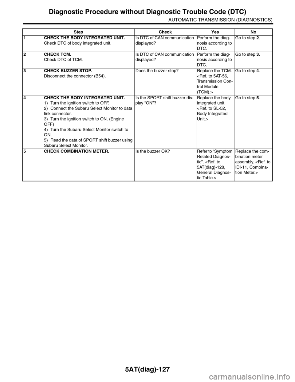
5AT(diag)-127
Diagnostic Procedure without Diagnostic Trouble Code (DTC)
AUTOMATIC TRANSMISSION (DIAGNOSTICS)
Step Check Yes No
1CHECK THE BODY INTEGRATED UNIT.
Check DTC of body integrated unit.
Is DTC of CAN communication
displayed?
Pe r for m t h e d ia g -
nosis according to
DTC.
Go to step 2.
2CHECK TCM.
Check DTC of TCM.
Is DTC of CAN communication
displayed?
Pe r for m t h e d ia g -
nosis according to
DTC.
Go to step 3.
3CHECK BUZZER STOP.
Disconnect the connector (B54).
Does the buzzer stop? Replace the TCM.
Tr a n s m i s s i o n C o n -
trol Module
(TCM).>
Go to step 4.
4CHECK THE BODY INTEGRATED UNIT.
1) Turn the ignition switch to OFF.
2) Connect the Subaru Select Monitor to data
link connector.
3) Turn the ignition switch to ON. (Engine
OFF)
4) Turn the Subaru Select Monitor switch to
ON.
5) Read the data of SPORT shift buzzer using
Subaru Select Monitor.
Is the SPORT shift buzzer dis-
play “ON”?
Replace the body
integrated unit.
Body Integrated
Unit.>
Go to step 5.
5CHECK COMBINATION METER.Is the buzzer OK? Refer to “Symptom
Related Diagnos-
tic”.
5AT(diag)-128,
General Diagnos-
tic Table.>
Replace the com-
bination meter
assembly.
IDI-11, Combina-
tion Meter.>
Page 2255 of 2453
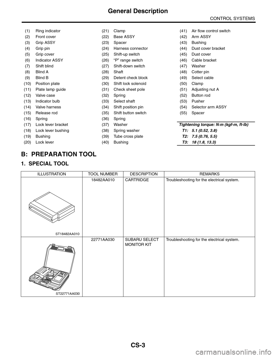
CS-3
General Description
CONTROL SYSTEMS
B: PREPARATION TOOL
1. SPECIAL TOOL
(1) Ring indicator (21) Clamp (41) Air flow control switch
(2) Front cover (22) Base ASSY (42) Arm ASSY
(3) Grip ASSY (23) Spacer (43) Bushing
(4) Grip pin (24) Harness connector (44) Dust cover bracket
(5) Grip cover (25) Shift-up switch (45) Dust cover
(6) Indicator ASSY (26) “P” range switch (46) Cable bracket
(7) Shift blind (27) Shift-down switch (47) Washer
(8) Blind A (28) Shaft (48) Cotter pin
(9) Blind B (29) Detent check block (49) Select cable
(10) Position plate (30) Shift lock solenoid (50) Clamp
(11) Plate lamp guide (31) Check sheet pole (51) Adjusting nut A
(12) Valve case (32) Spring (52) Button rod
(13) Indicator bulb (33) Select shaft (53) Pusher
(14) Valve harness (34) Shift position pin (54) Selector arm ASSY
(15) Release rod (35) Shift button switch (55) Spacer
(16) Spring (36) Spring
(17) Lock lever bracket (37) WasherTightening torque: N·m (kgf-m, ft-lb)
(18) Lock lever bushing (38) Spring washerT1: 5.1 (0.52, 3.8)
(19) Bushing (39) Tube cross plateT2: 7.5 (0.76, 5.5)
(20) Lock lever (40) BushingT3: 18 (1.8, 13.3)
ILLUSTRATION TOOL NUMBER DESCRIPTION REMARKS
18482AA010 CARTRIDGE Troubleshooting for the electrical system.
22771AA030 SUBARU SELECT
MONITOR KIT
Tr o u b l e s h o o t i n g f o r t h e e l e c t r i c a l s y s t e m .
ST18482AA010
ST22771AA030
Page 2256 of 2453
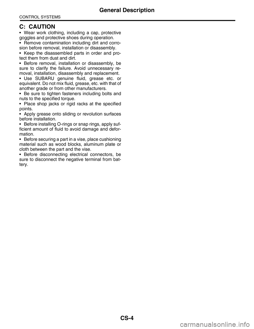
CS-4
General Description
CONTROL SYSTEMS
C: CAUTION
•Wear work clothing, including a cap, protective
goggles and protective shoes during operation.
•Remove contamination including dirt and corro-
sion before removal, installation or disassembly.
•Keep the disassembled parts in order and pro-
tect them from dust and dirt.
•Before removal, installation or disassembly, be
sure to clarify the failure. Avoid unnecessary re-
moval, installation, disassembly and replacement.
•Use SUBARU genuine fluid, grease etc. or
equivalent. Do not mix fluid, grease, etc. with that of
another grade or from other manufacturers.
•Be sure to tighten fasteners including bolts and
nuts to the specified torque.
•Place shop jacks or rigid racks at the specified
points.
•Apply grease onto sliding or revolution surfaces
before installation.
•Before installing O-rings or snap rings, apply suf-
ficient amount of fluid to avoid damage and defor-
mation.
•Before securing a part in a vise, place cushioning
material such as wood blocks, aluminum plate or
cloth between the part and the vise.
•Before disconnecting electrical connectors, be
sure to disconnect the negative terminal from bat-
tery.
Page 2263 of 2453
CS-11
AT Shift Lock Control System
CONTROL SYSTEMS
Step Check Yes No
1CHECK DTC OF BODY INTEGRATED UNIT.
Check DTC of the body integrated unit.
Diagnostic Trouble Code (DTC).>
Is the DTC of power line dis-
played on body integrated
unit?
Repair or replace it
according to the
DTC.
Go to step 2.
2CHECK HARNESS CONNECTOR BETWEEN
BODY INTEGRATED UNIT AND CHASSIS
GROUND.
1) Turn the ignition switch to OFF.
2) Measure the harness resistance between
the body integrated unit and chassis ground.
Connector & terminal
(i84) No. 21 — Chassis ground:
(B280) No. 22 — Chassis ground:
(B281) No. 8 — Chassis ground:
(B281) No. 9 — Chassis ground:
Is the resistance less than 1
Ω?
Go to step 3.Repair the open
circuit of harness
between the body
integrated unit and
chassis ground.
3CHECK POOR CONTACT.Is there poor contact in con-
nector?
Repair the poor
contact.
Check the body
integrated unit.
Page 2265 of 2453
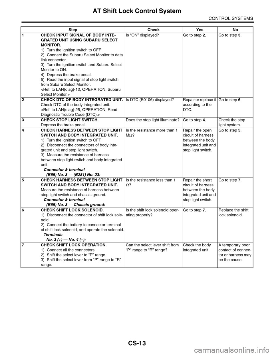
CS-13
AT Shift Lock Control System
CONTROL SYSTEMS
Step Check Yes No
1CHECK INPUT SIGNAL OF BODY INTE-
GRATED UNIT USING SUBARU SELECT
MONITOR.
1) Turn the ignition switch to OFF.
2) Connect the Subaru Select Monitor to data
link connector.
3) Turn the ignition switch and Subaru Select
Monitor to ON.
4) Depress the brake pedal.
5) Read the input signal of stop light switch
from Subaru Select Monitor.
Select Monitor.>
Is “ON” displayed? Go to step 2.Go to step 3.
2CHECK DTC OF BODY INTEGRATED UNIT.
Check DTC of the body integrated unit.
Diagnostic Trouble Code (DTC).>
Is DTC (B0106) displayed? Repair or replace it
according to the
DTC.
Go to step 6.
3CHECK STOP LIGHT SWITCH.
Depress the brake pedal.
Does the stop light illuminate? Go to step 4.Check the stop
light system.
4CHECK HARNESS BETWEEN STOP LIGHT
SWITCH AND BODY INTEGRATED UNIT.
1) Turn the ignition switch to OFF.
2) Disconnect the connectors of body inte-
grated unit and stop light switch.
3) Measure the resistance of harness
between stop light switch and body integrated
unit.
Connector & terminal
(B65) No. 3 — (B281) No. 23:
Is the resistance more than 1
MΩ?
Repair the open
circuit of harness
between the body
integrated unit and
stop light switch.
Go to step 5.
5CHECK HARNESS BETWEEN STOP LIGHT
SWITCH AND BODY INTEGRATED UNIT.
Measure the resistance of harness between
stop light switch and chassis ground.
Connector & terminal
(B65) No. 3 — Chassis ground:
Is the resistance less than 1
Ω?
Repair the short
circuit of harness
between the body
integrated unit and
stop light switch.
Go to step 7.
6CHECK SHIFT LOCK SOLENOID.
1) Disconnect the connector of shift lock sole-
noid.
2) Connect the battery to connector terminal
of shift lock solenoid, and operate the solenoid.
Te r m i n a l s
No. 3 (+) — No. 4 (–):
Is the shift lock solenoid oper-
ating properly?
Go to step 7.Replace the shift
lock solenoid.
7CHECK SHIFT LOCK OPERATION.
1) Connect all the connectors.
2) Shift the select lever to “P” range.
3) Shift the select lever from “P” range to “R”
range.
Can the select lever shift from
“P” range to “R” range?
Check the body
integrated unit.
A temporary poor
contact of connec-
tor or harness may
be the cause.
Page 2266 of 2453
CS-14
AT Shift Lock Control System
CONTROL SYSTEMS
4. SHIFT LOCK OF SELECT LEVER CANNOT BE RELEASED.
CS-00601
NO.8
E
B280B:
B281C:
C23C1
B6
B
ACC
IG
ACCOFFON
A1
NO.12
SBF-2MAIN SBF
SBF-6
B159
59
B116
4
3
B65
B30B20
B116
1234
B65B159
123456789
567821943102422 23 25111213141526 27281617181920 21
B281
5467821931022 231112131415242526 2716171828 29192021 30
B280i84
1234567891011121314151617181920212223242526272829303132333435
i84A:
12789563410 11 1219 20 2113 14 15 16 17 18222324
B54
NO.14
A:C: B:
BODY INTEGRATED UNIT
STOP LIGHT SWITCH
SHIFT LOCK SOLENOID
JOINT FUSE BOX
32
TCM
B54
B355
B352
34561278
*1*2
*1*2
*1*2
*1*2
43
B352
JOINTCONNECTOR
B355
JOINTCONNECTOR
BATTERY
1
*
: TERMINAL NO. OPTIONAL ARRANGEMENT AMONG 1, 2, 5 AND 6: TERMINAL NO. OPTIONAL ARRANGEMENT AMONG 3, 4, 7 AND 8
123456789101112
*
2