Page 1997 of 2453
PM-14
Engine Coolant
PERIODIC MAINTENANCE SERVICES
10.Engine Coolant
A: REPLACEMENT
1. REPLACEMENT OF ENGINE COOLANT
WARNING:
The radiator is of the pressurized type. Do not
attempt to open the radiator cap immediately
after the engine has been stopped.
1) Lift-up the vehicle.
2) Remove the under cover.
3) Place a container under drain pipe.
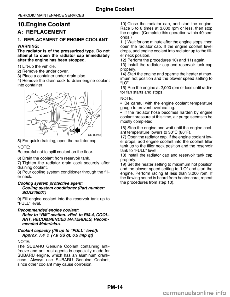
4) Remove the drain cock to drain engine coolant
into container.
5) For quick draining, open the radiator cap.
NOTE:
Be careful not to spill coolant on the floor.
6) Drain the coolant from reservoir tank.
7) Tighten the radiator drain cock securely after
draining coolant.
8) Pour cooling system conditioner through the fill-
er neck.
Cooling system protective agent:
Cooling system conditioner (Part number:
SOA345001)
9) Fill engine coolant into the reservoir tank up to
“FULL” level.
Recommended engine coolant:
Refer to “RM” section.
ANT, RECOMMENDED MATERIALS, Recom-
mended Materials.>
Coolant capacity (fill up to “FULL” level):
Approx. 7.4 2 (7.8 US qt, 6.5 Imp qt)
NOTE:
The SUBARU Genuine Coolant containing anti-
freeze and anti-rust agents is especially made for
SUBARU engine, which has an aluminum crank-
case. Always use SUBARU Genuine Coolant,
since other coolant may cause corrosion.
10) Close the radiator cap, and start the engine.
Race 5 to 6 times at 3,000 rpm or less, then stop
the engine. (Complete this operation within 40 sec-
onds.)
11) Wait for one minute after the engine stops, then
open the radiator cap. If the engine coolant level
drops, add engine coolant into radiator up to the fill-
er neck position.
12) Perform the procedures 10) and 11) again.
13) Install the radiator cap and reservoir tank cap
properly.
14) Start the engine and operate the heater at max-
imum hot position and the blower speed setting to
“LO”.
15) Run the engine at 2,000 rpm or less until radia-
tor fan starts and stops.
NOTE:
•Be careful with the engine coolant temperature
gauge to prevent overheating.
•If the radiator hose becomes harden by engine
coolant pressure at this time, air purge seems to be
mostly completed.
16) Stop the engine and wait until the engine cool-
ant temperature lowers to 30°C (86°F).
17) Open the radiator cap. If the engine coolant lev-
el drops, add engine coolant into the coolant filler
tank up to the filler neck position and the reservoir
tank to “FULL” level.
18) Install the radiator cap and reservoir tank cap
properly.
19) Set the heater setting to maximum hot position
and the blower speed setting to “LO” and start the
engine. Perform racing at less than 3,000 rpm. If
the flowing sound is heard from heater core, repeat
the procedures from step 10).
CO-00248
Page 2019 of 2453
5AT-3
General Description
AUTOMATIC TRANSMISSION
8. COOLING AND HARNESS
9. TRANSFER
10.FINAL REDUCTION GEAR
11.RECOMMENDED GEAR OIL
Cooling systemLiquid-cooler incorporated in
radiator
Tr a n s m i s s i o n h a r n e s s 2 0 + 8 p o l e s
Tr a n s f e r t y p eVa r i a b l e t o r q u e d i s t r i b u t i o n
(VTD)
Number of transfer clutch
drives & driven plates4
Reduction gear ratio 1.000 (41/41)
Fr o nt f in a l r e du ct i o n g ea r
ratio3.583
Lubrication oil
(1) Item (3) API standard
(2) Front differential gear oil (4) SAE viscosity No. and applicable
temperature
Fr o nt d if fer e nt i a l g ea r oi l c a pa ci t y
2(US qt, Imp qt)1.3 — 1.5 (1.4 — 1.6, 1.1 — 1.3)
MT-00001
(1)
(4)GL-5(3)
(2)
( C)( F)-30 -26 -15 15
9085W80W75W -90
25 30 -5 0-22-1523328659775
Page 2031 of 2453
5AT-15
General Description
AUTOMATIC TRANSMISSION
11.OIL COOLER PIPE AND OIL COOLER
(1) Radiator (4) ATF filterTightening torque: N·m (kgf-m, ft-lb)
(2) Clip (5) ATF filter bracketT: 7.5 (0.76, 5.5)
(3) ATF hose (6) ATF cooler pipe
(1)
(2)
(3)
(3)
(2)
(2)
(2)
(2)
(2)
(6)
(4)
(5)
(3)(3)
(3)
(3)
(2)
(2)
(2)
(2)
(2)
(2)
T
T
T
(3)
AT-03253
Page 2073 of 2453
5AT-57
ATF Cooler Pipe & Hose
AUTOMATIC TRANSMISSION
20.ATF Cooler Pipe & Hose
A: REMOVAL
1) Set the vehicle on a lift.
2) Lift-up the vehicle.
3) Remove the under cover.
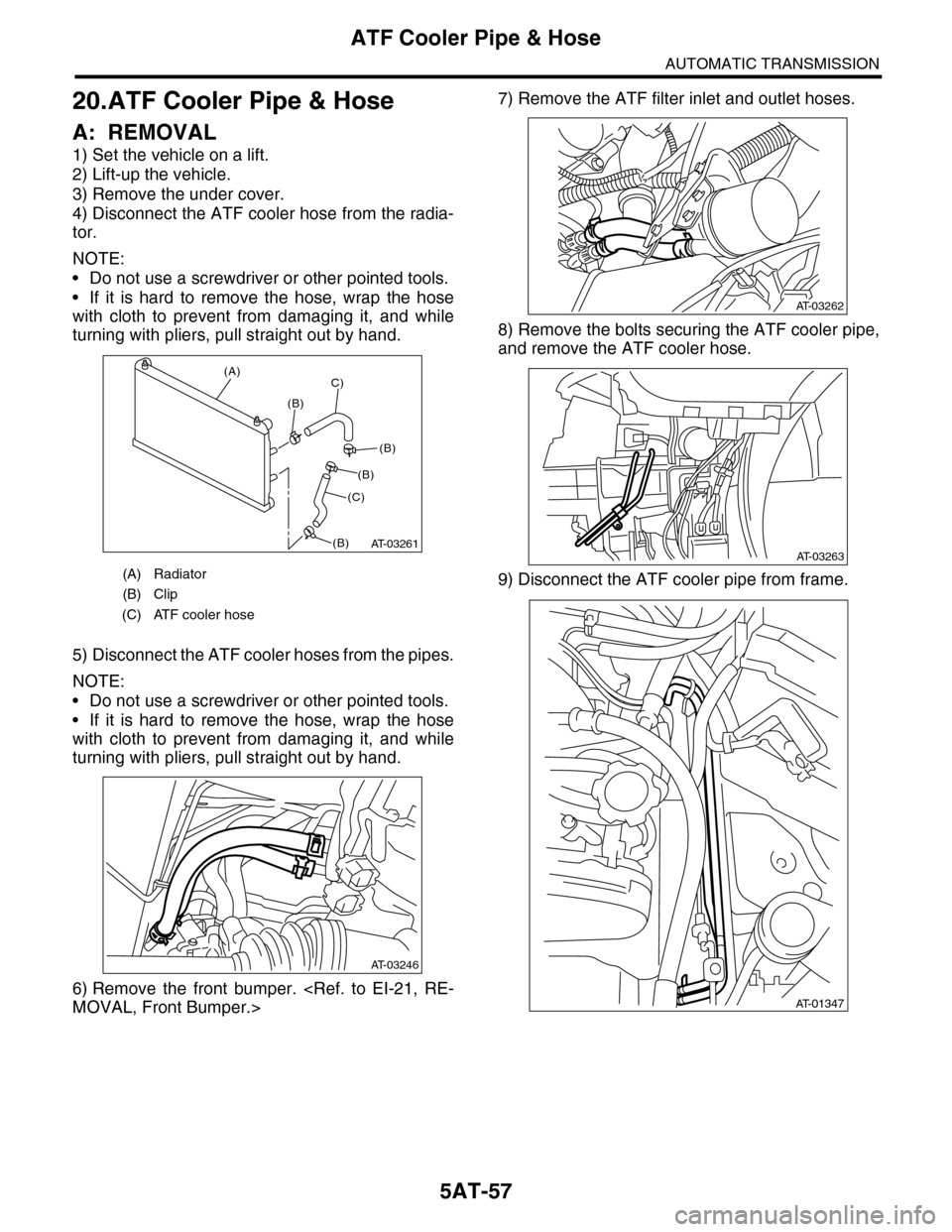
4) Disconnect the ATF cooler hose from the radia-
tor.
NOTE:
•Do not use a screwdriver or other pointed tools.
•If it is hard to remove the hose, wrap the hose
with cloth to prevent from damaging it, and while
turning with pliers, pull straight out by hand.
5) Disconnect the ATF cooler hoses from the pipes.
NOTE:
•Do not use a screwdriver or other pointed tools.
•If it is hard to remove the hose, wrap the hose
with cloth to prevent from damaging it, and while
turning with pliers, pull straight out by hand.
6) Remove the front bumper.
MOVAL, Front Bumper.>
7) Remove the ATF filter inlet and outlet hoses.
8) Remove the bolts securing the ATF cooler pipe,
and remove the ATF cooler hose.
9) Disconnect the ATF cooler pipe from frame.(A) Radiator
(B) Clip
(C) ATF cooler hose
AT-03261
(A)
(B)
C)
(C)
(B)
(B)
(B)
AT-03246
AT-03262
AT-03263
AT-01347
Page 2075 of 2453
5AT-59
ATF Cooler Pipe & Hose
AUTOMATIC TRANSMISSION
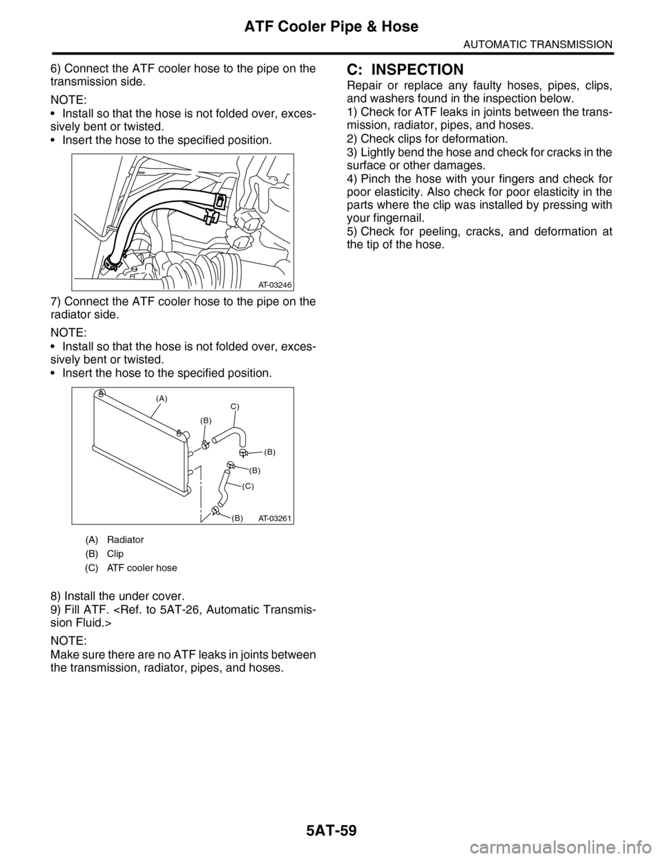
6) Connect the ATF cooler hose to the pipe on the
transmission side.
NOTE:
•Install so that the hose is not folded over, exces-
sively bent or twisted.
•Insert the hose to the specified position.
7) Connect the ATF cooler hose to the pipe on the
radiator side.
NOTE:
•Install so that the hose is not folded over, exces-
sively bent or twisted.
•Insert the hose to the specified position.
8) Install the under cover.
9) Fill ATF.
sion Fluid.>
NOTE:
Make sure there are no ATF leaks in joints between
the transmission, radiator, pipes, and hoses.
C: INSPECTION
Repair or replace any faulty hoses, pipes, clips,
and washers found in the inspection below.
1) Check for ATF leaks in joints between the trans-
mission, radiator, pipes, and hoses.
2) Check clips for deformation.
3) Lightly bend the hose and check for cracks in the
surface or other damages.
4) Pinch the hose with your fingers and check for
poor elasticity. Also check for poor elasticity in the
parts where the clip was installed by pressing with
your fingernail.
5) Check for peeling, cracks, and deformation at
the tip of the hose.
(A) Radiator
(B) Clip
(C) ATF cooler hose
AT-03246
AT-03261
(A)
(B)
C)
(C)
(B)
(B)
(B)
Page 2298 of 2453
WI-14
Working Precautions
WIRING SYSTEM
2. Working Precautions
A: PRECAUTIONS WHEN WORKING
WITH THE PARTS MOUNTED ON
THE VEHICLE
1) When working under a vehicle which is jacked-
up, always be sure to use rigid rack.
2) The parking brake must always be applied dur-
ing working. Also, in automatic transmission vehi-
cles, keep the select lever set to the P (Parking)
range.
3) Be sure the workshop is properly ventilated
when running the engine. Further, be careful not to
touch the belt or fan while the engine is operating.
4) Be careful not to touch hot metal parts, especial-
ly the radiator and exhaust system immediately af-
ter the engine has been turned off.
B: PRECAUTIONS IN TROUBLE DI-
AGNOSIS AND REPAIR OF ELEC-
TRIC PARTS
1) The battery cable must be disconnected from
the battery’s (–) terminal, and the ignition switch
must be set to the OFF position, unless otherwise
required by the diagnostics.
2) Securely fasten the wiring harness with clamps
and slips so that the harness does not interfere with
the body end parts or edges and bolts or screws.
3) When installing parts, be careful not to catch
them on the wiring harness.
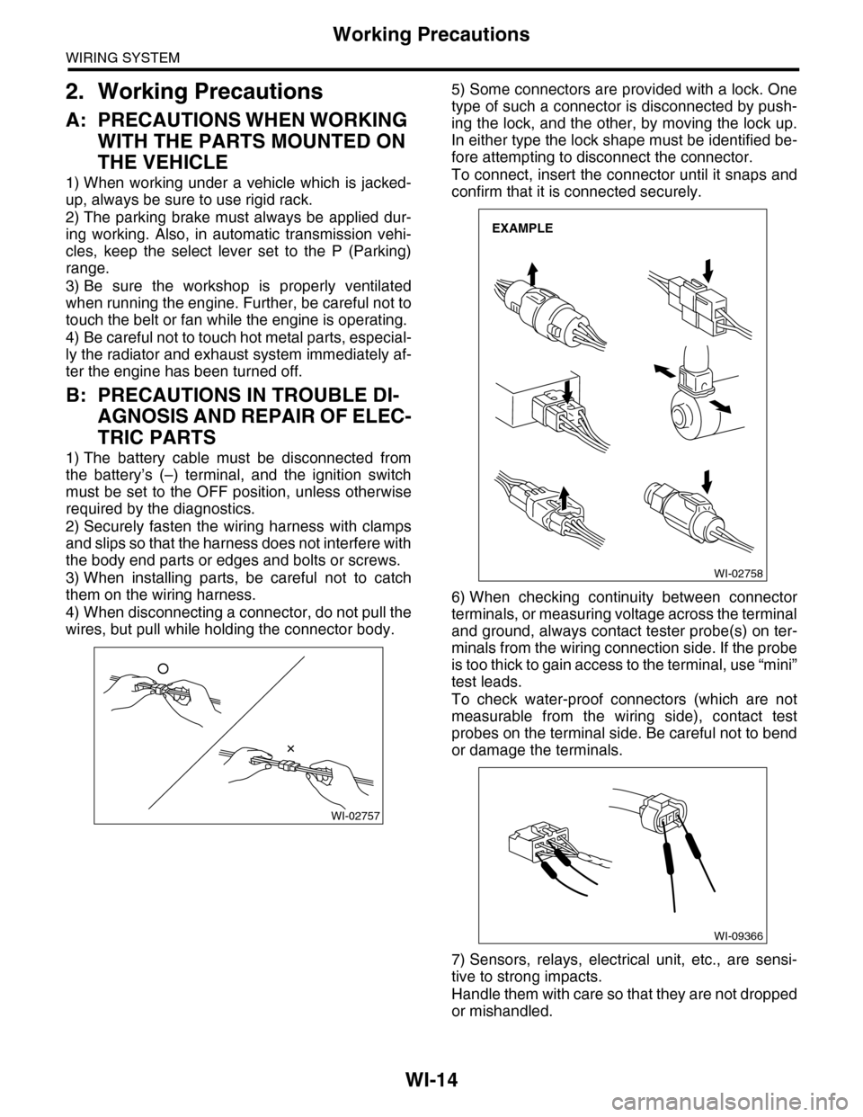
4) When disconnecting a connector, do not pull the
wires, but pull while holding the connector body.
5) Some connectors are provided with a lock. One
type of such a connector is disconnected by push-
ing the lock, and the other, by moving the lock up.
In either type the lock shape must be identified be-
fore attempting to disconnect the connector.
To connect, insert the connector until it snaps and
confirm that it is connected securely.
6) When checking continuity between connector
terminals, or measuring voltage across the terminal
and ground, always contact tester probe(s) on ter-
minals from the wiring connection side. If the probe
is too thick to gain access to the terminal, use “mini”
test leads.
To check water-proof connectors (which are not
measurable from the wiring side), contact test
probes on the terminal side. Be careful not to bend
or damage the terminals.
7) Sensors, relays, electrical unit, etc., are sensi-
tive to strong impacts.
Handle them with care so that they are not dropped
or mishandled.
WI-02757
WI-02758
EXAMPLE
WI-09366
Page 2316 of 2453
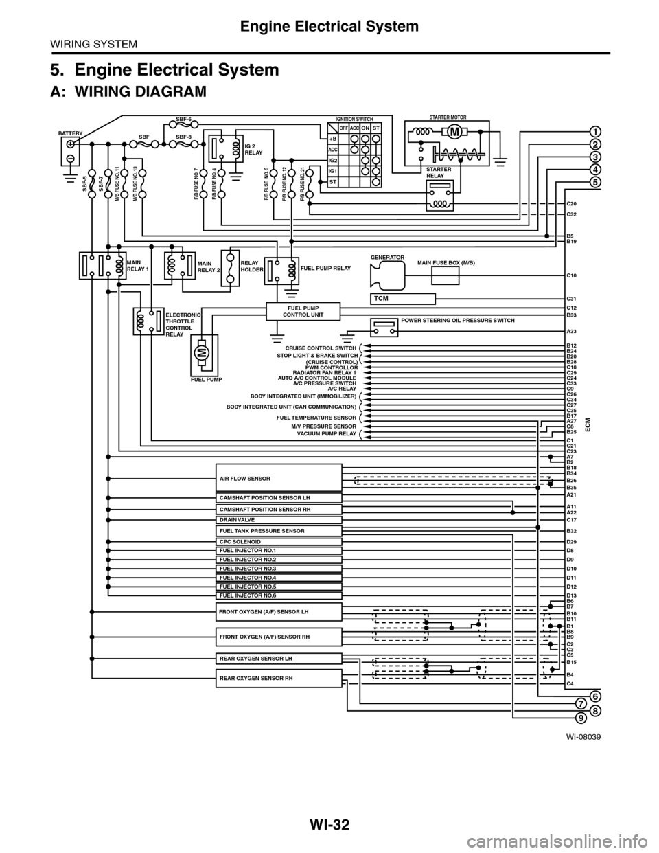
WI-32
Engine Electrical System
WIRING SYSTEM
5. Engine Electrical System
A: WIRING DIAGRAM
WI-08039
678
1
2
3
4
5
C20
C32
C31
B5B19
B33
A33
C10
ECMC1B25C8A27
C21C23A7
D29
B2
BATTERY
M/B FUSE NO. 11SBF-7
SBF
SBF-5
SBF-8
SBF-6
STARTERRELAY
IG 2RELAY
IGNITION SWITCHOFF+B
ACC
IG2
IG1
ACCONST
ST
STARTER MOTOR
MAINRELAY 1
ELECTRONICTHROTTLECONTROLRELAY
FUEL PUMP RELAY
FUEL PUMP
FUEL PUMPCONTROL UNIT
MAINRELAY 2RELAYHOLDER
A21
A11A22
B34
B35
B7B6
B11B10
B9B8
C2
B26AIR FLOW SENSOR
CAMSHAFT POSITION SENSOR LH
CPC SOLENOID
B1
C3C5B15
B4C4
POWER STEERING OIL PRESSURE SWITCH
C12
MAIN FUSE BOX (M/B)GENERATOR
B18
TCM
D8FUEL INJECTOR NO.1D9D10D11
PWM CONTROLLORAUTO A/C CONTROL MODULE
A/C RELAY
BODY INTEGRATED UNIT (CAN COMMUNICATION)
FUEL TEMPERATURE SENSOR
VACUUM PUMP RELAY
BODY INTEGRATED UNIT (IMMOBILIZER)
C18C29C24C33
C27
B24B12
B20B28
C26C34
C35B17
CRUISE CONTROL SWITCH
FUEL INJECTOR NO.2FUEL INJECTOR NO.3
C17DRAIN VALVE
FUEL INJECTOR NO.4D12D13FUEL INJECTOR NO.5FUEL INJECTOR NO.6
FRONT OXYGEN (A/F) SENSOR RH
REAR OXYGEN SENSOR RH
REAR OXYGEN SENSOR LH
FRONT OXYGEN (A/F) SENSOR LH
A/C PRESSURE SWITCH
M/V PRESSURE SENSOR
RADIATOR FAN RELAY 1
STOP LIGHT & BRAKE SWITCH(CRUISE CONTROL)
C9
FUEL TANK PRESSURE SENSORB32
M/B FUSE NO. 13F/B FUSE NO. 7F/B FUSE NO. 4F/B FUSE NO. 5F/B FUSE NO. 12F/B FUSE NO. 21
CAMSHAFT POSITION SENSOR RH
9
Page 2319 of 2453
WI-35
Engine Electrical System
WIRING SYSTEM
WI-08042
E/G-02E/G-02
ECM
WL
C26
BP
C34
REF. TO AT CONTROLSYSTEM [5AT-05] REF. TO CRUISECONTROL SYSTEM [C/C-01] REF. TO STOP LIGHTSYSTEM [S/L-01]REF. TO IMMOBILIZER SYSTEM [IMB-01] REF. TO RADIATOR FAN SYSTEM [R/F-01] REF. TO FRONT AIR CONDITIONER SYSTEM [F-A/C-01•02]
GL
C31
C:B136B:B135A:B134
WL
B12
LP
B24
BrR
B28
Y
B20
PW
C24
YB
C33
LOr
C9
REF. TO VACUUMPUMP SYSTEM [VPC-01]
Y
C8
RB
A27
WR
B25
RY
C18
GR
C29
C:B136B135B:
5672134
29
101112131415252416
30
98171819202821222332312627333435
16101112131415252430
9871718192028212223293231
123456
2726333435
A:B134
85610 11 12 13 14 157213416
3019 20 2228 29
91718252123 24323126 2733 34