2009 SUBARU TRIBECA radiator
[x] Cancel search: radiatorPage 1774 of 2453
GD(H6DO)-162
Diagnostic Trouble Code (DTC) Detecting Criteria
GENERAL DESCRIPTION
8. FAIL SAFE
•ABS wheel speed sensor signal process: Vehicle speed = 10 km/h (6 MPH)
•ISC control: ISC feedback amount calculation prohibited
•Radiator fan control: Send the duty signal 50% to the controller.
9. ECM OPERATION AT DTC SETTING
Memorize the freeze frame data. (For test mode $02)
Page 1791 of 2453
GD(H6DO)-179
Diagnostic Trouble Code (DTC) Detecting Criteria
GENERAL DESCRIPTION
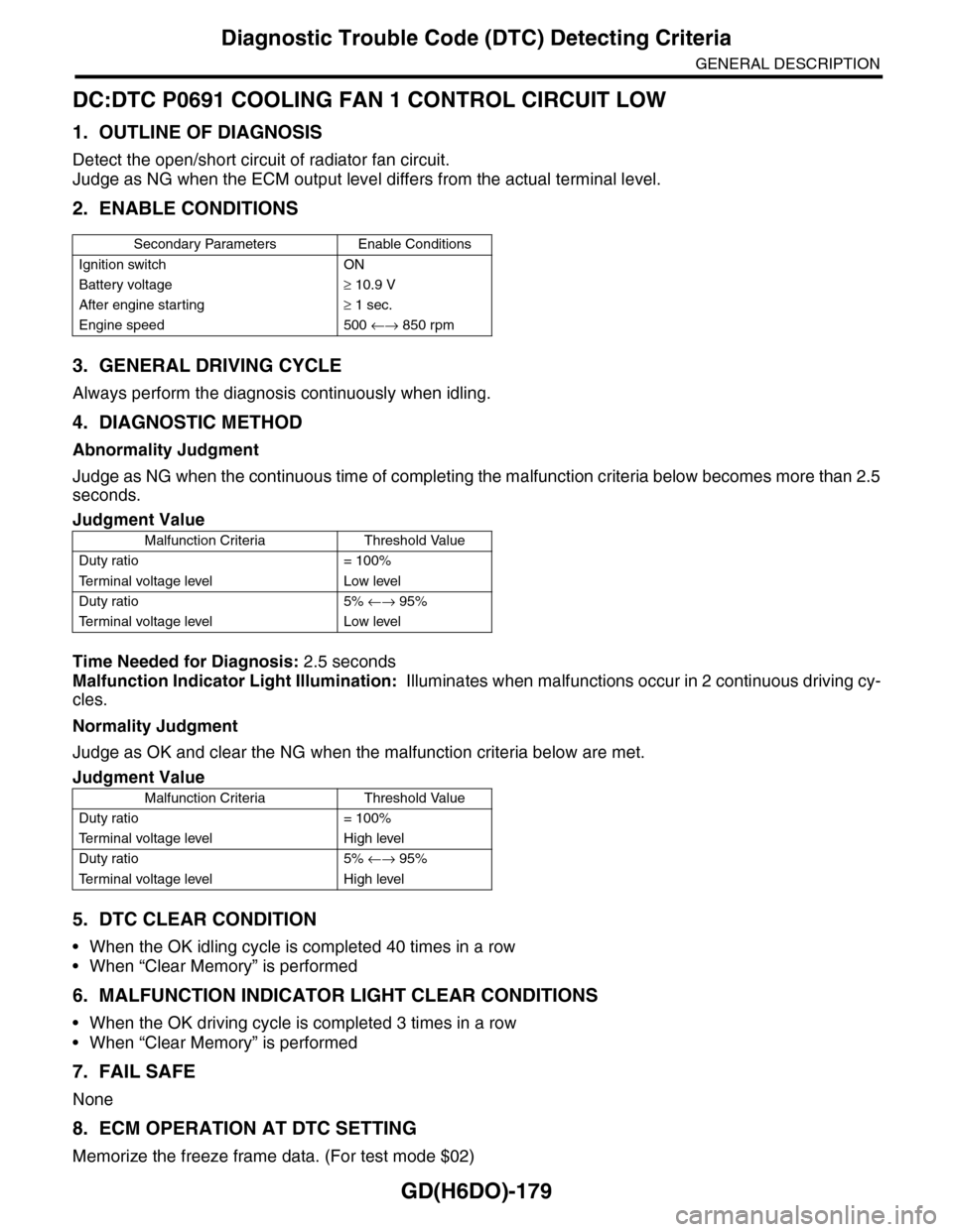
DC:DTC P0691 COOLING FAN 1 CONTROL CIRCUIT LOW
1. OUTLINE OF DIAGNOSIS
Detect the open/short circuit of radiator fan circuit.
Judge as NG when the ECM output level differs from the actual terminal level.
2. ENABLE CONDITIONS
3. GENERAL DRIVING CYCLE
Always perform the diagnosis continuously when idling.
4. DIAGNOSTIC METHOD
Abnormality Judgment
Judge as NG when the continuous time of completing the malfunction criteria below becomes more than 2.5
seconds.
Time Needed for Diagnosis: 2.5 seconds
Malfunction Indicator Light Illumination: Illuminates when malfunctions occur in 2 continuous driving cy-
cles.
Normality Judgment
Judge as OK and clear the NG when the malfunction criteria below are met.
5. DTC CLEAR CONDITION
•When the OK idling cycle is completed 40 times in a row
•When “Clear Memory” is performed
6. MALFUNCTION INDICATOR LIGHT CLEAR CONDITIONS
•When the OK driving cycle is completed 3 times in a row
•When “Clear Memory” is performed
7. FAIL SAFE
None
8. ECM OPERATION AT DTC SETTING
Memorize the freeze frame data. (For test mode $02)
Secondary Parameters Enable Conditions
Ignition switch ON
Battery voltage≥ 10.9 V
After engine starting≥ 1 sec.
Engine speed 500 ←→ 850 rpm
Judgment Value
Malfunction Criteria Threshold Value
Duty ratio = 100%
Te r m i n a l v o l t a g e l e v e l L o w l e v e l
Duty ratio 5% ←→ 95%
Te r m i n a l v o l t a g e l e v e l L o w l e v e l
Judgment Value
Malfunction Criteria Threshold Value
Duty ratio = 100%
Te r m i n a l v o l t a g e l e v e l H i g h l e v e l
Duty ratio 5% ←→ 95%
Te r m i n a l v o l t a g e l e v e l H i g h l e v e l
Page 1792 of 2453
GD(H6DO)-180
Diagnostic Trouble Code (DTC) Detecting Criteria
GENERAL DESCRIPTION
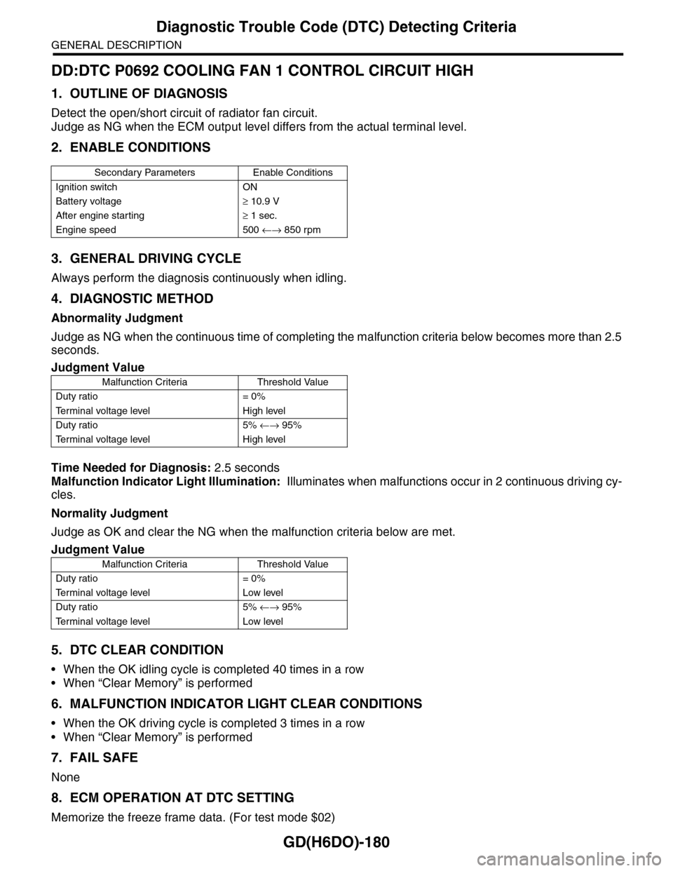
DD:DTC P0692 COOLING FAN 1 CONTROL CIRCUIT HIGH
1. OUTLINE OF DIAGNOSIS
Detect the open/short circuit of radiator fan circuit.
Judge as NG when the ECM output level differs from the actual terminal level.
2. ENABLE CONDITIONS
3. GENERAL DRIVING CYCLE
Always perform the diagnosis continuously when idling.
4. DIAGNOSTIC METHOD
Abnormality Judgment
Judge as NG when the continuous time of completing the malfunction criteria below becomes more than 2.5
seconds.
Time Needed for Diagnosis: 2.5 seconds
Malfunction Indicator Light Illumination: Illuminates when malfunctions occur in 2 continuous driving cy-
cles.
Normality Judgment
Judge as OK and clear the NG when the malfunction criteria below are met.
5. DTC CLEAR CONDITION
•When the OK idling cycle is completed 40 times in a row
•When “Clear Memory” is performed
6. MALFUNCTION INDICATOR LIGHT CLEAR CONDITIONS
•When the OK driving cycle is completed 3 times in a row
•When “Clear Memory” is performed
7. FAIL SAFE
None
8. ECM OPERATION AT DTC SETTING
Memorize the freeze frame data. (For test mode $02)
Secondary Parameters Enable Conditions
Ignition switch ON
Battery voltage≥ 10.9 V
After engine starting≥ 1 sec.
Engine speed 500 ←→ 850 rpm
Judgment Value
Malfunction Criteria Threshold Value
Duty ratio = 0%
Te r m i n a l v o l t a g e l e v e l H i g h l e v e l
Duty ratio 5% ←→ 95%
Te r m i n a l v o l t a g e l e v e l H i g h l e v e l
Judgment Value
Malfunction Criteria Threshold Value
Duty ratio = 0%
Te r m i n a l v o l t a g e l e v e l L o w l e v e l
Duty ratio 5% ←→ 95%
Te r m i n a l v o l t a g e l e v e l L o w l e v e l
Page 1857 of 2453
LU(H6DO)-8
Oil Pump
LUBRICATION
4. Oil Pump
A: REMOVAL
1) Remove the collector cover.
2) Disconnect the ground cable from battery.
3) Lift-up the vehicle.
4) Remove the under cover.
5) Drain engine coolant.
MENT, Engine Coolant.>
6) Lower the vehicle.
7) Remove the radiator.
8) Remove the V-belts.
9) Remove the front chain cover.
10) Remove the timing chain.
11) Remove the crank sprocket.
12) Remove the oil pump cover.
13) Remove the inner rotor and outer rotor.
B: INSTALLATION
1) Apply a coat of engine oil to the whole area of in-
ner rotor and outer rotor.
2) Set the inner rotor onto opening edge of crank
shaft, and install the inner rotor, and then assemble
the outer rotor.
3) Install the oil pump cover.
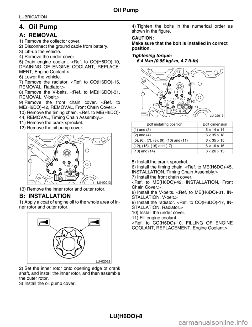
4) Tighten the bolts in the numerical order as
shown in the figure.
CAUTION:
Make sure that the bolt is installed in correct
position.
Tightening torque:
6.4 N·m (0.65 kgf-m, 4.7 ft-lb)
5) Install the crank sprocket.
6) Install the timing chain.
7) Install the front chain cover.
8) Install the V-belts.
9) Install the radiator.
10) Install the under cover.
11) Fill engine coolant.
LU-02012
LU-02032
Bolt installing position Bolt dimension
(1) and (3) 6 × 14 × 14
(2) and (4) 6 × 35 × 18
(5), (6), (7), (8), (9), (10) and (11) 6 × 35 × 15
(12), (15), (16) and (17) 6 × 16 × 16
(13) and (14) 6 × 26 × 15
LU-02013
(3)(7)
(2)
(4)
(9)
(5)
(8)(1)(6)(12)
(13)(14)(15)
(16)(17)
(11)(10)
Page 1888 of 2453
ME(H6DO)-22
Idle Speed
MECHANICAL
3. Idle Speed
A: INSPECTION
1) Before checking the idle speed, check the fol-
lowing item:
(1) Check the air cleaner element is free from
clogging, ignition timing is correct, spark plugs
are in good condition, and hoses are connected
properly.
(2) Check the malfunction indicator light does
not illuminate.
2) Idle the engine.
3) Stop the engine, and turn the ignition switch to
OFF.
4) Insert the cartridge to Subaru Select Monitor.
5) Connect the Subaru Select Monitor to data link
connector.
6) Turn the ignition switch to ON and Subaru Select
Monitor switch to ON.
7) Select {Each System Check} in Main Menu.
8) Select {Engine} in Selection Menu.
9) Select {Current Data Display & Save} in Engine
Control System Diagnosis.
10) Select {Data Display} in Data Display Menu.
11) Start the engine, and read the engine idle
speed.
12) Check the idle speed when no-loaded. (Head-
light, heater fan, rear defroster, radiator fan, A/C
and etc. are OFF)
Idle speed [No load and gears in neutral]:
650±50 rpm
13) Check the idle speed when loaded. (Turn the A/
C switch to “ON” and operate the compressor for at
least one minute before measurement.)
Idle speed [A/C ON and gears in neutral]:
770±50 rpm
NOTE:
Idle speed cannot be adjusted manually, because
the idle speed is automatically adjusted. If the pre-
scribed idle speed cannot be maintained, refer to
General On-board Diagnosis Table under “Engine
Control System”.
Page 1898 of 2453
ME(H6DO)-32
Engine Assembly
MECHANICAL
10.Engine Assembly
A: REMOVAL
1) Set the vehicle on a lift.
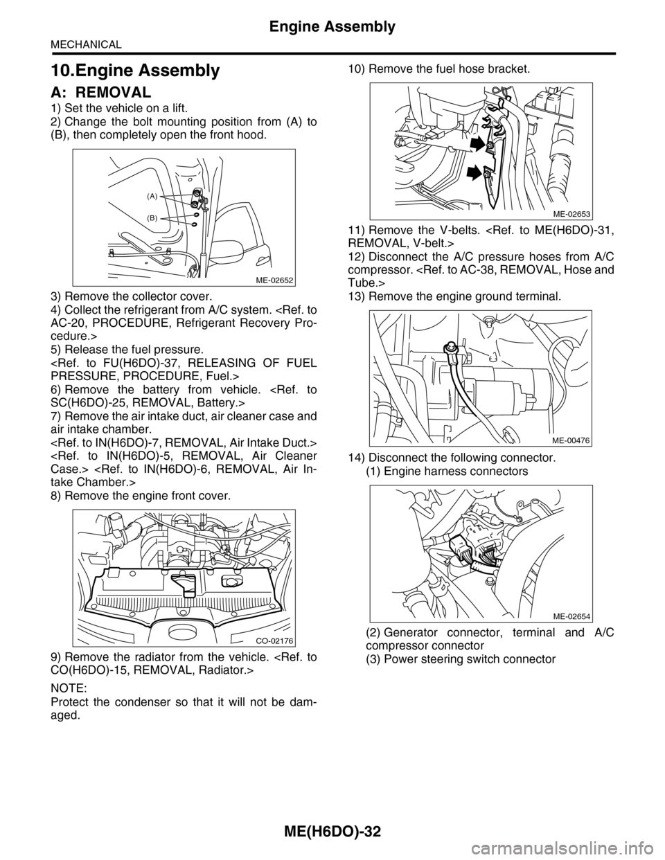
2) Change the bolt mounting position from (A) to
(B), then completely open the front hood.
3) Remove the collector cover.
4) Collect the refrigerant from A/C system.
cedure.>
5) Release the fuel pressure.
6) Remove the battery from vehicle.
7) Remove the air intake duct, air cleaner case and
air intake chamber.
8) Remove the engine front cover.
9) Remove the radiator from the vehicle.
NOTE:
Protect the condenser so that it will not be dam-
aged.
10) Remove the fuel hose bracket.
11) Remove the V-belts.
12) Disconnect the A/C pressure hoses from A/C
compressor.
13) Remove the engine ground terminal.
14) Disconnect the following connector.
(1) Engine harness connectors
(2) Generator connector, terminal and A/C
compressor connector
(3) Power steering switch connector
ME-02652
(A)
(B)
CO-02176
ME-02653
ME-00476
ME-02654
Page 1904 of 2453
ME(H6DO)-38
Engine Assembly
MECHANICAL
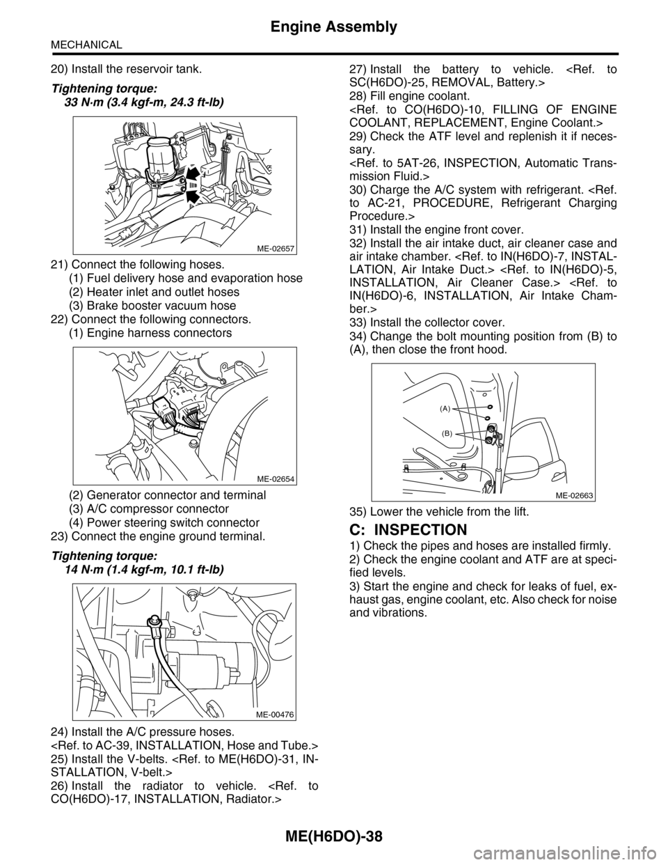
20) Install the reservoir tank.
Tightening torque:
33 N·m (3.4 kgf-m, 24.3 ft-lb)
21) Connect the following hoses.
(1) Fuel delivery hose and evaporation hose
(2) Heater inlet and outlet hoses
(3) Brake booster vacuum hose
22) Connect the following connectors.
(1) Engine harness connectors
(2) Generator connector and terminal
(3) A/C compressor connector
(4) Power steering switch connector
23) Connect the engine ground terminal.
Tightening torque:
14 N·m (1.4 kgf-m, 10.1 ft-lb)
24) Install the A/C pressure hoses.
25) Install the V-belts.
26) Install the radiator to vehicle.
27) Install the battery to vehicle.
28) Fill engine coolant.
29) Check the ATF level and replenish it if neces-
sary.
30) Charge the A/C system with refrigerant.
Procedure.>
31) Install the engine front cover.
32) Install the air intake duct, air cleaner case and
air intake chamber.
ber.>
33) Install the collector cover.
34) Change the bolt mounting position from (B) to
(A), then close the front hood.
35) Lower the vehicle from the lift.
C: INSPECTION
1) Check the pipes and hoses are installed firmly.
2) Check the engine coolant and ATF are at speci-
fied levels.
3) Start the engine and check for leaks of fuel, ex-
haust gas, engine coolant, etc. Also check for noise
and vibrations.
ME-02657
ME-02654
ME-00476
ME-02663
(A)
(B)
Page 1996 of 2453
PM-13
Cooling System
PERIODIC MAINTENANCE SERVICES
9. Cooling System
A: INSPECTION
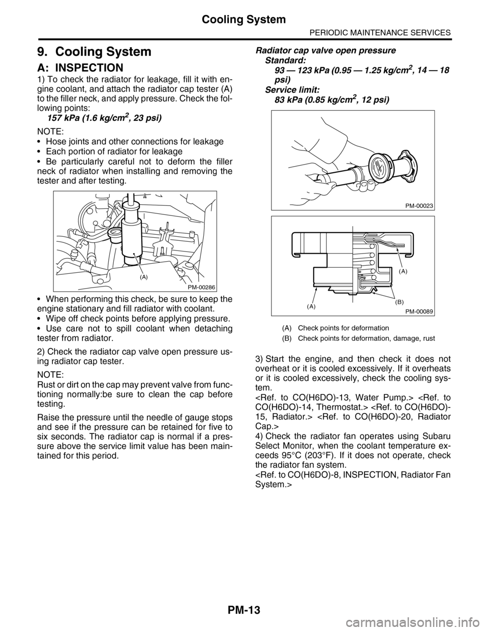
1) To check the radiator for leakage, fill it with en-
gine coolant, and attach the radiator cap tester (A)
to the filler neck, and apply pressure. Check the fol-
lowing points:
157 kPa (1.6 kg/cm2, 23 psi)
NOTE:
•Hose joints and other connections for leakage
•Each portion of radiator for leakage
•Be particularly careful not to deform the filler
neck of radiator when installing and removing the
tester and after testing.
•When performing this check, be sure to keep the
engine stationary and fill radiator with coolant.
•Wipe off check points before applying pressure.
•Use care not to spill coolant when detaching
tester from radiator.
2) Check the radiator cap valve open pressure us-
ing radiator cap tester.
NOTE:
Rust or dirt on the cap may prevent valve from func-
tioning normally:be sure to clean the cap before
testing.
Raise the pressure until the needle of gauge stops
and see if the pressure can be retained for five to
six seconds. The radiator cap is normal if a pres-
sure above the service limit value has been main-
tained for this period.
Radiator cap valve open pressure
Standard:
93 — 123 kPa (0.95 — 1.25 kg/cm2, 14 — 18
psi)
Service limit:
83 kPa (0.85 kg/cm2, 12 psi)
3) Start the engine, and then check it does not
overheat or it is cooled excessively. If it overheats
or it is cooled excessively, check the cooling sys-
tem.
4) Check the radiator fan operates using Subaru
Select Monitor, when the coolant temperature ex-
ceeds 95°C (203°F). If it does not operate, check
the radiator fan system.
PM-00286
(A)
(A) Check points for deformation
(B) Check points for deformation, damage, rust
PM-00023
PM-00089
(B)(A)
(A)