2009 SUBARU TRIBECA g sensor
[x] Cancel search: g sensorPage 1516 of 2453
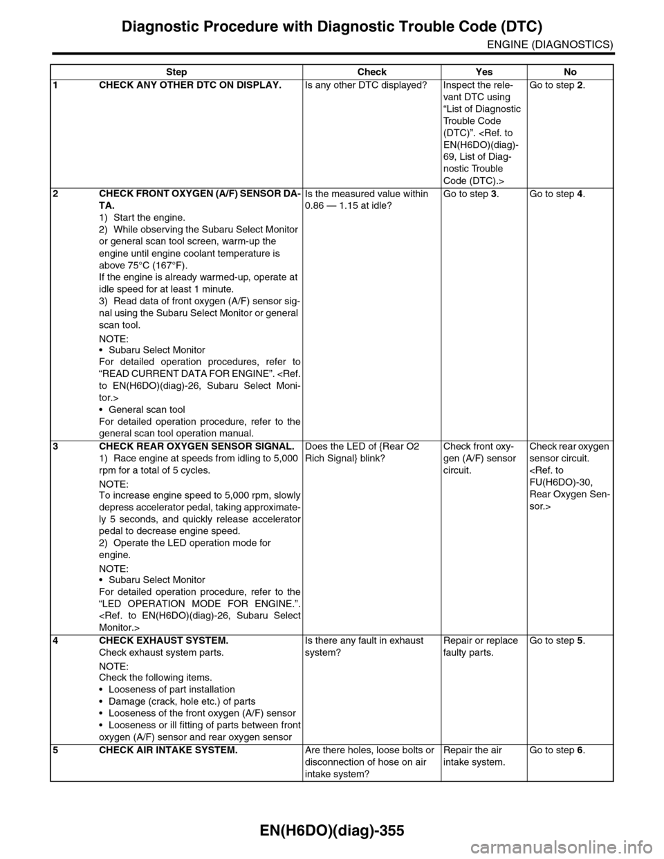
EN(H6DO)(diag)-355
Diagnostic Procedure with Diagnostic Trouble Code (DTC)
ENGINE (DIAGNOSTICS)
Step Check Yes No
1CHECK ANY OTHER DTC ON DISPLAY.Is any other DTC displayed? Inspect the rele-
vant DTC using
“List of Diagnostic
Tr o u b l e C o d e
(DTC)”.
69, List of Diag-
nostic Trouble
Code (DTC).>
Go to step 2.
2CHECK FRONT OXYGEN (A/F) SENSOR DA-
TA.
1) Start the engine.
2) While observing the Subaru Select Monitor
or general scan tool screen, warm-up the
engine until engine coolant temperature is
above 75°C (167°F).
If the engine is already warmed-up, operate at
idle speed for at least 1 minute.
3) Read data of front oxygen (A/F) sensor sig-
nal using the Subaru Select Monitor or general
scan tool.
NOTE:
•Subaru Select Monitor
For detailed operation procedures, refer to
“READ CURRENT DATA FOR ENGINE”.
tor.>
•General scan tool
For detailed operation procedure, refer to the
general scan tool operation manual.
Is the measured value within
0.86 — 1.15 at idle?
Go to step 3.Go to step 4.
3CHECK REAR OXYGEN SENSOR SIGNAL.
1) Race engine at speeds from idling to 5,000
rpm for a total of 5 cycles.
NOTE:To increase engine speed to 5,000 rpm, slowly
depress accelerator pedal, taking approximate-
ly 5 seconds, and quickly release accelerator
pedal to decrease engine speed.
2) Operate the LED operation mode for
engine.
NOTE:•Subaru Select Monitor
For detailed operation procedure, refer to the
“LED OPERATION MODE FOR ENGINE.”.
Does the LED of {Rear O2
Rich Signal} blink?
Check front oxy-
gen (A/F) sensor
circuit.
Check rear oxygen
sensor circuit.
Rear Oxygen Sen-
sor.>
4 CHECK EXHAUST SYSTEM.
Check exhaust system parts.
NOTE:Check the following items.
•Looseness of part installation
•Damage (crack, hole etc.) of parts
•Looseness of the front oxygen (A/F) sensor
•Looseness or ill fitting of parts between front
oxygen (A/F) sensor and rear oxygen sensor
Is there any fault in exhaust
system?
Repair or replace
faulty par ts.
Go to step 5.
5CHECK AIR INTAKE SYSTEM.Are there holes, loose bolts or
disconnection of hose on air
intake system?
Repair the air
intake system.
Go to step 6.
Page 1517 of 2453
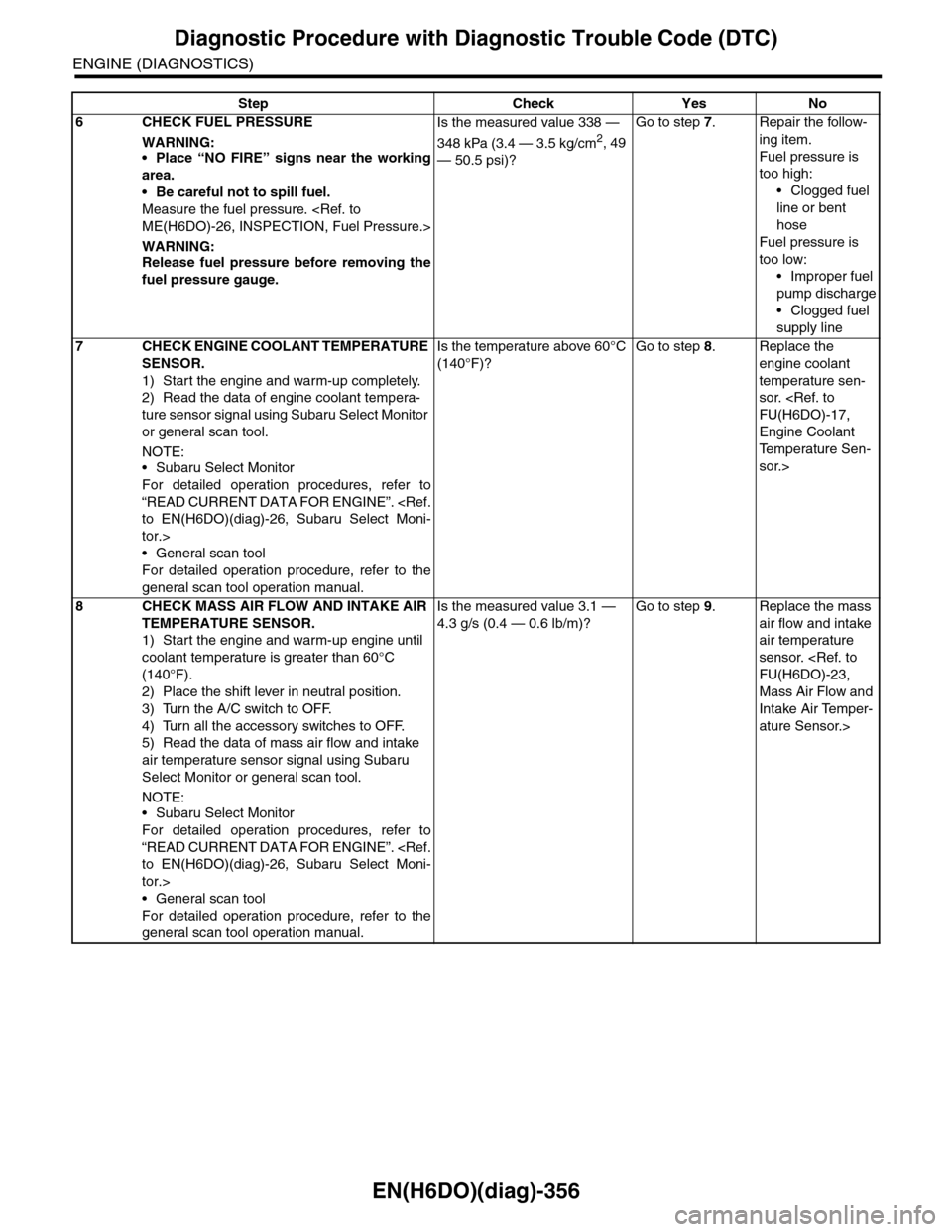
EN(H6DO)(diag)-356
Diagnostic Procedure with Diagnostic Trouble Code (DTC)
ENGINE (DIAGNOSTICS)
6CHECK FUEL PRESSURE
WARNING:•Place “NO FIRE” signs near the working
area.
•Be careful not to spill fuel.
Measure the fuel pressure.
WARNING:Release fuel pressure before removing the
fuel pressure gauge.
Is the measured value 338 —
348 kPa (3.4 — 3.5 kg/cm2, 49
— 50.5 psi)?
Go to step 7.Repair the follow-
ing item.
Fuel pressure is
too high:
•Clogged fuel
line or bent
hose
Fuel pressure is
too low:
•Improper fuel
pump discharge
•Clogged fuel
supply line
7CHECK ENGINE COOLANT TEMPERATURE
SENSOR.
1) Start the engine and warm-up completely.
2) Read the data of engine coolant tempera-
ture sensor signal using Subaru Select Monitor
or general scan tool.
NOTE:•Subaru Select Monitor
For detailed operation procedures, refer to
“READ CURRENT DATA FOR ENGINE”.
tor.>
•General scan tool
For detailed operation procedure, refer to the
general scan tool operation manual.
Is the temperature above 60°C
(140°F)?
Go to step 8.Replace the
engine coolant
temperature sen-
sor.
Engine Coolant
Te m p e r a t u r e S e n -
sor.>
8CHECK MASS AIR FLOW AND INTAKE AIR
TEMPERATURE SENSOR.
1) Start the engine and warm-up engine until
coolant temperature is greater than 60°C
(140°F).
2) Place the shift lever in neutral position.
3) Turn the A/C switch to OFF.
4) Turn all the accessory switches to OFF.
5) Read the data of mass air flow and intake
air temperature sensor signal using Subaru
Select Monitor or general scan tool.
NOTE:•Subaru Select Monitor
For detailed operation procedures, refer to
“READ CURRENT DATA FOR ENGINE”.
tor.>
•General scan tool
For detailed operation procedure, refer to the
general scan tool operation manual.
Is the measured value 3.1 —
4.3 g/s (0.4 — 0.6 lb/m)?
Go to step 9.Replace the mass
air flow and intake
air temperature
sensor.
Mass Air Flow and
Intake Air Temper-
ature Sensor.>
Step Check Yes No
Page 1518 of 2453
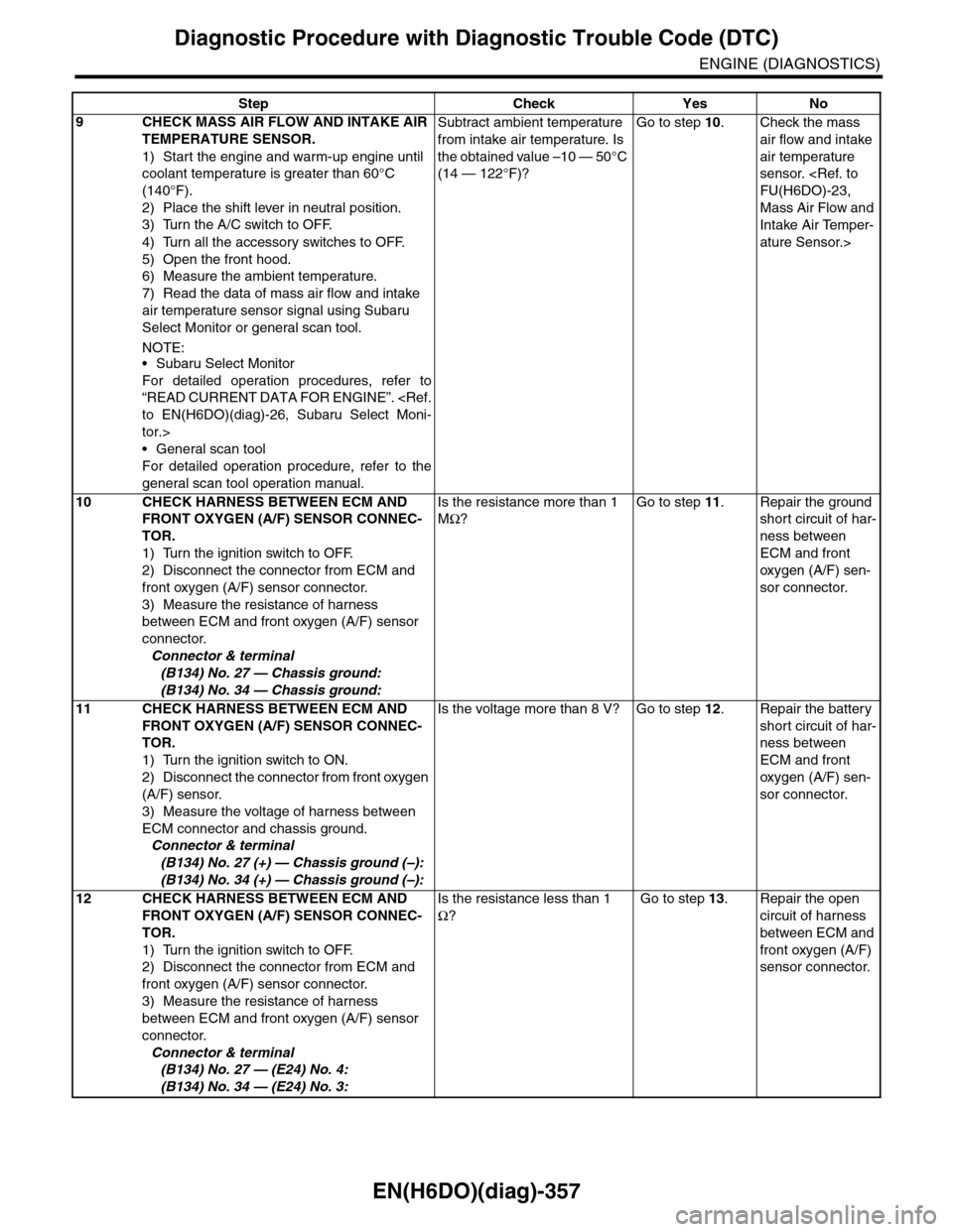
EN(H6DO)(diag)-357
Diagnostic Procedure with Diagnostic Trouble Code (DTC)
ENGINE (DIAGNOSTICS)
9CHECK MASS AIR FLOW AND INTAKE AIR
TEMPERATURE SENSOR.
1) Start the engine and warm-up engine until
coolant temperature is greater than 60°C
(140°F).
2) Place the shift lever in neutral position.
3) Turn the A/C switch to OFF.
4) Turn all the accessory switches to OFF.
5) Open the front hood.
6) Measure the ambient temperature.
7) Read the data of mass air flow and intake
air temperature sensor signal using Subaru
Select Monitor or general scan tool.
NOTE:•Subaru Select Monitor
For detailed operation procedures, refer to
“READ CURRENT DATA FOR ENGINE”.
tor.>
•General scan tool
For detailed operation procedure, refer to the
general scan tool operation manual.
Subtract ambient temperature
from intake air temperature. Is
the obtained value –10 — 50°C
(14 — 122°F)?
Go to step 10.Check the mass
air flow and intake
air temperature
sensor.
Mass Air Flow and
Intake Air Temper-
ature Sensor.>
10 CHECK HARNESS BETWEEN ECM AND
FRONT OXYGEN (A/F) SENSOR CONNEC-
TOR.
1) Turn the ignition switch to OFF.
2) Disconnect the connector from ECM and
front oxygen (A/F) sensor connector.
3) Measure the resistance of harness
between ECM and front oxygen (A/F) sensor
connector.
Connector & terminal
(B134) No. 27 — Chassis ground:
(B134) No. 34 — Chassis ground:
Is the resistance more than 1
MΩ?
Go to step 11.Repair the ground
short circuit of har-
ness between
ECM and front
oxygen (A/F) sen-
sor connector.
11 CHECK HARNESS BETWEEN ECM AND
FRONT OXYGEN (A/F) SENSOR CONNEC-
TOR.
1) Turn the ignition switch to ON.
2) Disconnect the connector from front oxygen
(A/F) sensor.
3) Measure the voltage of harness between
ECM connector and chassis ground.
Connector & terminal
(B134) No. 27 (+) — Chassis ground (–):
(B134) No. 34 (+) — Chassis ground (–):
Is the voltage more than 8 V? Go to step 12.Repair the battery
short circuit of har-
ness between
ECM and front
oxygen (A/F) sen-
sor connector.
12 CHECK HARNESS BETWEEN ECM AND
FRONT OXYGEN (A/F) SENSOR CONNEC-
TOR.
1) Turn the ignition switch to OFF.
2) Disconnect the connector from ECM and
front oxygen (A/F) sensor connector.
3) Measure the resistance of harness
between ECM and front oxygen (A/F) sensor
connector.
Connector & terminal
(B134) No. 27 — (E24) No. 4:
(B134) No. 34 — (E24) No. 3:
Is the resistance less than 1
Ω?
Go to step 13.Repair the open
circuit of harness
between ECM and
front oxygen (A/F)
sensor connector.
Step Check Yes No
Page 1519 of 2453
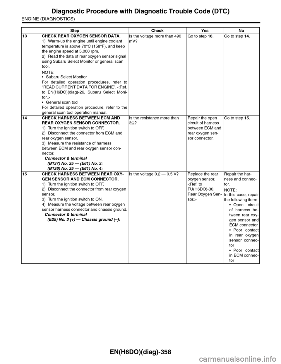
EN(H6DO)(diag)-358
Diagnostic Procedure with Diagnostic Trouble Code (DTC)
ENGINE (DIAGNOSTICS)
13 CHECK REAR OXYGEN SENSOR DATA.
1) Warm-up the engine until engine coolant
temperature is above 70°C (158°F), and keep
the engine speed at 5,000 rpm.
2) Read the data of rear oxygen sensor signal
using Subaru Select Monitor or general scan
tool.
NOTE:•Subaru Select Monitor
For detailed operation procedures, refer to
“READ CURRENT DATA FOR ENGINE”.
tor.>
•General scan tool
For detailed operation procedure, refer to the
general scan tool operation manual.
Is the voltage more than 490
mV?
Go to step 16.Go to step 14.
14 CHECK HARNESS BETWEEN ECM AND
REAR OXYGEN SENSOR CONNECTOR.
1) Turn the ignition switch to OFF.
2) Disconnect the connector from ECM and
rear oxygen sensor.
3) Measure the resistance of harness
between ECM and rear oxygen sensor con-
nector.
Connector & terminal
(B137) No. 25 — (E61) No. 3:
(B136) No. 35 — (E61) No. 4:
Is the resistance more than
3Ω?
Repair the open
circuit of harness
between ECM and
rear oxygen sen-
sor connector.
Go to step 15.
15 CHECK HARNESS BETWEEN REAR OXY-
GEN SENSOR AND ECM CONNECTOR.
1) Turn the ignition switch to OFF.
2) Disconnect the connector from rear oxygen
sensor.
3) Turn the ignition switch to ON.
4) Measure the voltage between rear oxygen
sensor harness connector and chassis ground.
Connector & terminal
(E25) No. 3 (+) — Chassis ground (–):
Is the voltage 0.2 — 0.5 V? Replace the rear
oxygen sensor.
Rear Oxygen Sen-
sor.>
Repair the har-
ness and connec-
tor.
NOTE:In this case, repair
the following item:
•Open circuit
of harness be-
tween rear oxy-
gen sensor and
ECM connector
•Poor contact
in rear oxygen
sensor connec-
tor
•Poor contact
in ECM connec-
tor
Step Check Yes No
Page 1520 of 2453
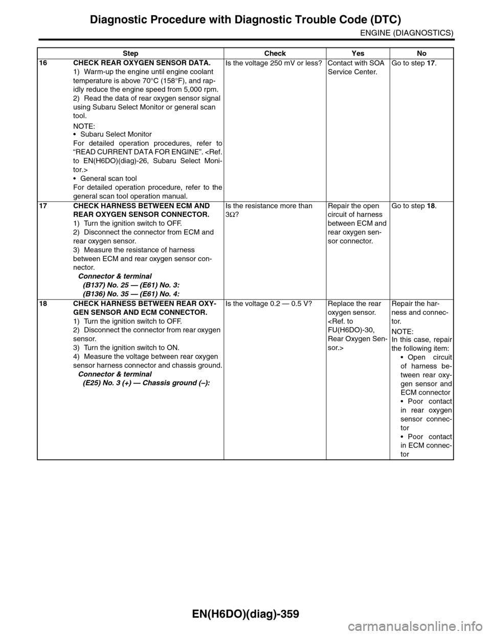
EN(H6DO)(diag)-359
Diagnostic Procedure with Diagnostic Trouble Code (DTC)
ENGINE (DIAGNOSTICS)
16 CHECK REAR OXYGEN SENSOR DATA.
1) Warm-up the engine until engine coolant
temperature is above 70°C (158°F), and rap-
idly reduce the engine speed from 5,000 rpm.
2) Read the data of rear oxygen sensor signal
using Subaru Select Monitor or general scan
tool.
NOTE:•Subaru Select Monitor
For detailed operation procedures, refer to
“READ CURRENT DATA FOR ENGINE”.
tor.>
•General scan tool
For detailed operation procedure, refer to the
general scan tool operation manual.
Is the voltage 250 mV or less? Contact with SOA
Service Center.
Go to step 17.
17 CHECK HARNESS BETWEEN ECM AND
REAR OXYGEN SENSOR CONNECTOR.
1) Turn the ignition switch to OFF.
2) Disconnect the connector from ECM and
rear oxygen sensor.
3) Measure the resistance of harness
between ECM and rear oxygen sensor con-
nector.
Connector & terminal
(B137) No. 25 — (E61) No. 3:
(B136) No. 35 — (E61) No. 4:
Is the resistance more than
3Ω?
Repair the open
circuit of harness
between ECM and
rear oxygen sen-
sor connector.
Go to step 18.
18 CHECK HARNESS BETWEEN REAR OXY-
GEN SENSOR AND ECM CONNECTOR.
1) Turn the ignition switch to OFF.
2) Disconnect the connector from rear oxygen
sensor.
3) Turn the ignition switch to ON.
4) Measure the voltage between rear oxygen
sensor harness connector and chassis ground.
Connector & terminal
(E25) No. 3 (+) — Chassis ground (–):
Is the voltage 0.2 — 0.5 V? Replace the rear
oxygen sensor.
Rear Oxygen Sen-
sor.>
Repair the har-
ness and connec-
tor.
NOTE:In this case, repair
the following item:
•Open circuit
of harness be-
tween rear oxy-
gen sensor and
ECM connector
•Poor contact
in rear oxygen
sensor connec-
tor
•Poor contact
in ECM connec-
tor
Step Check Yes No
Page 1523 of 2453
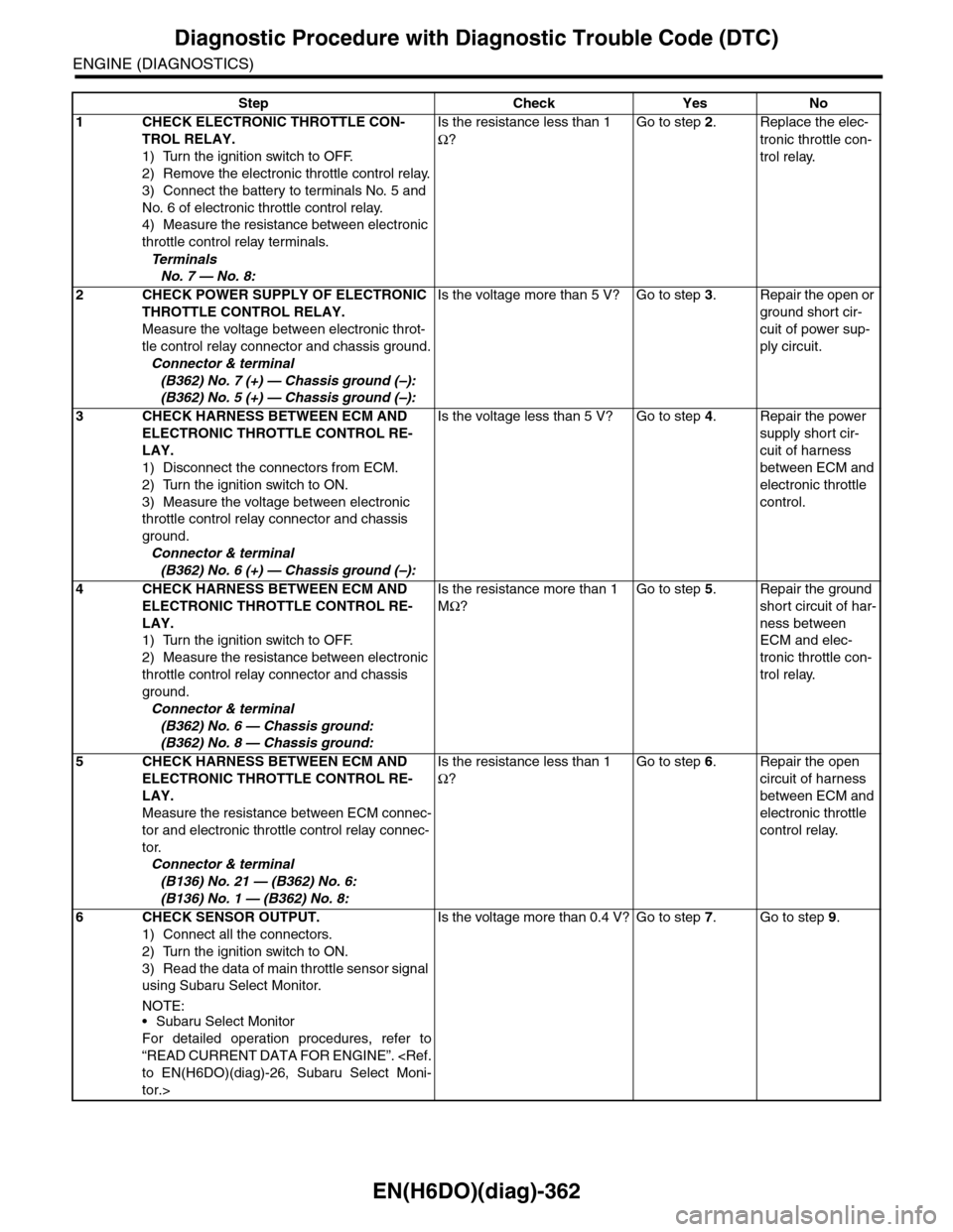
EN(H6DO)(diag)-362
Diagnostic Procedure with Diagnostic Trouble Code (DTC)
ENGINE (DIAGNOSTICS)
Step Check Yes No
1CHECK ELECTRONIC THROTTLE CON-
TROL RELAY.
1) Turn the ignition switch to OFF.
2) Remove the electronic throttle control relay.
3) Connect the battery to terminals No. 5 and
No. 6 of electronic throttle control relay.
4) Measure the resistance between electronic
throttle control relay terminals.
Te r m i n a l s
No. 7 — No. 8:
Is the resistance less than 1
Ω?
Go to step 2.Replace the elec-
tronic throttle con-
trol relay.
2CHECK POWER SUPPLY OF ELECTRONIC
THROTTLE CONTROL RELAY.
Measure the voltage between electronic throt-
tle control relay connector and chassis ground.
Connector & terminal
(B362) No. 7 (+) — Chassis ground (–):
(B362) No. 5 (+) — Chassis ground (–):
Is the voltage more than 5 V? Go to step 3.Repair the open or
ground short cir-
cuit of power sup-
ply circuit.
3CHECK HARNESS BETWEEN ECM AND
ELECTRONIC THROTTLE CONTROL RE-
LAY.
1) Disconnect the connectors from ECM.
2) Turn the ignition switch to ON.
3) Measure the voltage between electronic
throttle control relay connector and chassis
ground.
Connector & terminal
(B362) No. 6 (+) — Chassis ground (–):
Is the voltage less than 5 V? Go to step 4.Repair the power
supply short cir-
cuit of harness
between ECM and
electronic throttle
control.
4CHECK HARNESS BETWEEN ECM AND
ELECTRONIC THROTTLE CONTROL RE-
LAY.
1) Turn the ignition switch to OFF.
2) Measure the resistance between electronic
throttle control relay connector and chassis
ground.
Connector & terminal
(B362) No. 6 — Chassis ground:
(B362) No. 8 — Chassis ground:
Is the resistance more than 1
MΩ?
Go to step 5.Repair the ground
short circuit of har-
ness between
ECM and elec-
tronic throttle con-
trol relay.
5CHECK HARNESS BETWEEN ECM AND
ELECTRONIC THROTTLE CONTROL RE-
LAY.
Measure the resistance between ECM connec-
tor and electronic throttle control relay connec-
tor.
Connector & terminal
(B136) No. 21 — (B362) No. 6:
(B136) No. 1 — (B362) No. 8:
Is the resistance less than 1
Ω?
Go to step 6.Repair the open
circuit of harness
between ECM and
electronic throttle
control relay.
6CHECK SENSOR OUTPUT.
1) Connect all the connectors.
2) Turn the ignition switch to ON.
3) Read the data of main throttle sensor signal
using Subaru Select Monitor.
NOTE:•Subaru Select Monitor
For detailed operation procedures, refer to
“READ CURRENT DATA FOR ENGINE”.
tor.>
Is the voltage more than 0.4 V? Go to step 7.Go to step 9.
Page 1524 of 2453
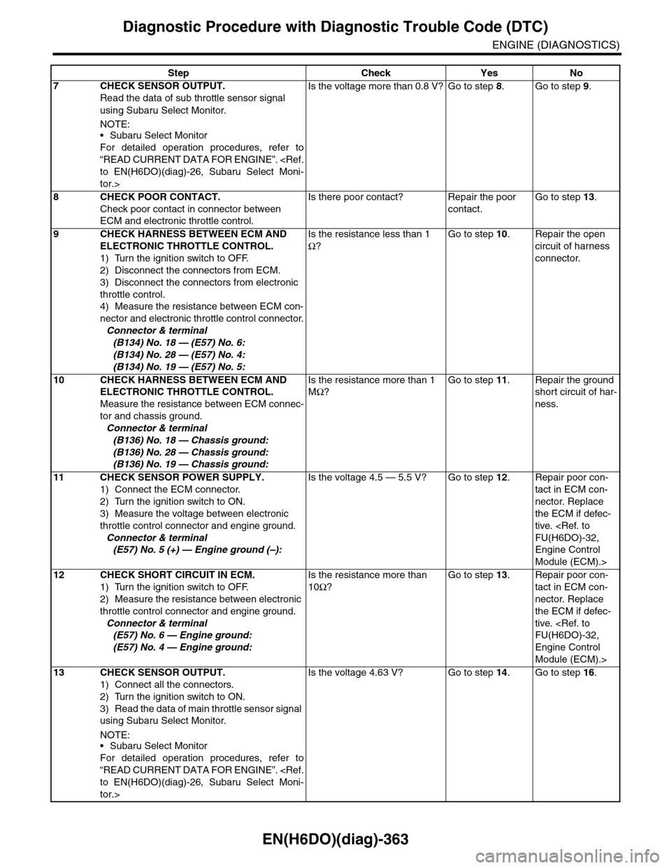
EN(H6DO)(diag)-363
Diagnostic Procedure with Diagnostic Trouble Code (DTC)
ENGINE (DIAGNOSTICS)
7CHECK SENSOR OUTPUT.
Read the data of sub throttle sensor signal
using Subaru Select Monitor.
NOTE:•Subaru Select Monitor
For detailed operation procedures, refer to
“READ CURRENT DATA FOR ENGINE”.
tor.>
Is the voltage more than 0.8 V? Go to step 8.Go to step 9.
8CHECK POOR CONTACT.
Check poor contact in connector between
ECM and electronic throttle control.
Is there poor contact? Repair the poor
contact.
Go to step 13.
9CHECK HARNESS BETWEEN ECM AND
ELECTRONIC THROTTLE CONTROL.
1) Turn the ignition switch to OFF.
2) Disconnect the connectors from ECM.
3) Disconnect the connectors from electronic
throttle control.
4) Measure the resistance between ECM con-
nector and electronic throttle control connector.
Connector & terminal
(B134) No. 18 — (E57) No. 6:
(B134) No. 28 — (E57) No. 4:
(B134) No. 19 — (E57) No. 5:
Is the resistance less than 1
Ω?
Go to step 10.Repair the open
circuit of harness
connector.
10 CHECK HARNESS BETWEEN ECM AND
ELECTRONIC THROTTLE CONTROL.
Measure the resistance between ECM connec-
tor and chassis ground.
Connector & terminal
(B136) No. 18 — Chassis ground:
(B136) No. 28 — Chassis ground:
(B136) No. 19 — Chassis ground:
Is the resistance more than 1
MΩ?
Go to step 11.Repair the ground
short circuit of har-
ness.
11 CHECK SENSOR POWER SUPPLY.
1) Connect the ECM connector.
2) Turn the ignition switch to ON.
3) Measure the voltage between electronic
throttle control connector and engine ground.
Connector & terminal
(E57) No. 5 (+) — Engine ground (–):
Is the voltage 4.5 — 5.5 V? Go to step 12.Repair poor con-
tact in ECM con-
nector. Replace
the ECM if defec-
tive.
Engine Control
Module (ECM).>
12 CHECK SHORT CIRCUIT IN ECM.
1) Turn the ignition switch to OFF.
2) Measure the resistance between electronic
throttle control connector and engine ground.
Connector & terminal
(E57) No. 6 — Engine ground:
(E57) No. 4 — Engine ground:
Is the resistance more than
10Ω?
Go to step 13.Repair poor con-
tact in ECM con-
nector. Replace
the ECM if defec-
tive.
Engine Control
Module (ECM).>
13 CHECK SENSOR OUTPUT.
1) Connect all the connectors.
2) Turn the ignition switch to ON.
3) Read the data of main throttle sensor signal
using Subaru Select Monitor.
NOTE:•Subaru Select Monitor
For detailed operation procedures, refer to
“READ CURRENT DATA FOR ENGINE”.
tor.>
Is the voltage 4.63 V? Go to step 14.Go to step 16.
Step Check Yes No
Page 1525 of 2453
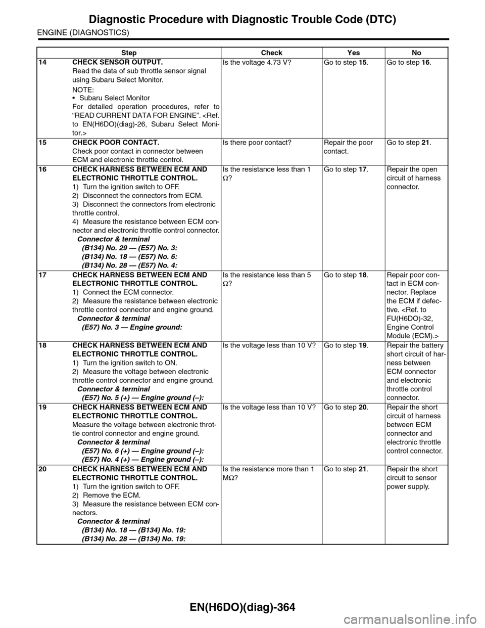
EN(H6DO)(diag)-364
Diagnostic Procedure with Diagnostic Trouble Code (DTC)
ENGINE (DIAGNOSTICS)
14 CHECK SENSOR OUTPUT.
Read the data of sub throttle sensor signal
using Subaru Select Monitor.
NOTE:•Subaru Select Monitor
For detailed operation procedures, refer to
“READ CURRENT DATA FOR ENGINE”.
tor.>
Is the voltage 4.73 V? Go to step 15.Go to step 16.
15 CHECK POOR CONTACT.
Check poor contact in connector between
ECM and electronic throttle control.
Is there poor contact? Repair the poor
contact.
Go to step 21.
16 CHECK HARNESS BETWEEN ECM AND
ELECTRONIC THROTTLE CONTROL.
1) Turn the ignition switch to OFF.
2) Disconnect the connectors from ECM.
3) Disconnect the connectors from electronic
throttle control.
4) Measure the resistance between ECM con-
nector and electronic throttle control connector.
Connector & terminal
(B134) No. 29 — (E57) No. 3:
(B134) No. 18 — (E57) No. 6:
(B134) No. 28 — (E57) No. 4:
Is the resistance less than 1
Ω?
Go to step 17.Repair the open
circuit of harness
connector.
17 CHECK HARNESS BETWEEN ECM AND
ELECTRONIC THROTTLE CONTROL.
1) Connect the ECM connector.
2) Measure the resistance between electronic
throttle control connector and engine ground.
Connector & terminal
(E57) No. 3 — Engine ground:
Is the resistance less than 5
Ω?
Go to step 18.Repair poor con-
tact in ECM con-
nector. Replace
the ECM if defec-
tive.
Engine Control
Module (ECM).>
18 CHECK HARNESS BETWEEN ECM AND
ELECTRONIC THROTTLE CONTROL.
1) Turn the ignition switch to ON.
2) Measure the voltage between electronic
throttle control connector and engine ground.
Connector & terminal
(E57) No. 5 (+) — Engine ground (–):
Is the voltage less than 10 V? Go to step 19.Repair the battery
short circuit of har-
ness between
ECM connector
and electronic
throttle control
connector.
19 CHECK HARNESS BETWEEN ECM AND
ELECTRONIC THROTTLE CONTROL.
Measure the voltage between electronic throt-
tle control connector and engine ground.
Connector & terminal
(E57) No. 6 (+) — Engine ground (–):
(E57) No. 4 (+) — Engine ground (–):
Is the voltage less than 10 V? Go to step 20.Repair the short
circuit of harness
between ECM
connector and
electronic throttle
control connector.
20 CHECK HARNESS BETWEEN ECM AND
ELECTRONIC THROTTLE CONTROL.
1) Turn the ignition switch to OFF.
2) Remove the ECM.
3) Measure the resistance between ECM con-
nectors.
Connector & terminal
(B134) No. 18 — (B134) No. 19:
(B134) No. 28 — (B134) No. 19:
Is the resistance more than 1
MΩ?
Go to step 21.Repair the short
circuit to sensor
power supply.
Step Check Yes No