Page 2008 of 2453
PM-25
Suspension
PERIODIC MAINTENANCE SERVICES
4. WHEEL ALIGNMENT OF FRONT SUS-
PENSION
1) Check the alignment of front suspension to en-
sure that following items conform to standard val-
ues.
•Toe-in
•Camber
•Caster
•Steering angle
2) When the caster angle does not conform to ref-
erence obviously, visually inspect the following
components and replace deformed parts.
•Suspension components [Strut assembly, cross-
member, front arm, etc.]
•Parts connecting suspension and body
3) When the toe-in and camber are out of standard
value, adjust them so that they conform to standard
value.
4) When the right-and-left turning angles of tire are
out of standard, adjust to standard value.
5. WHEEL ALIGNMENT OF REAR SUS-
PENSION
1) Check the alignment of rear suspension to en-
sure that following items are within standard val-
ues.
•Toe-in
•Camber
•Thrust angle
2) When the camber angle does not conform to
standard value, visually inspect the following com-
ponents. If the deformation is observed, replace the
damaged parts.
•Suspension components [Shock absorber, rear
upper arm, front lateral link, rear lateral link, rear
trailing link, sub frame]
•Parts connecting suspension and body
3) When the toe-in and thrust angle are out of stan-
dard value, adjust them so that they conform to
standard value.
6. OIL LEAKAGE OF STRUT AND SHOCK
ABSORBER
Visually inspect the front strut and rear shock ab-
sorber for oil leakage. Replace the front strut and
rear shock absorber if oil leaks excessively.
7. TIGHTNESS OF BOLTS AND NUTS
Check the bolts and nuts for looseness. Retighten
the bolts and nuts to specified torque. If the self-
locking nuts and bolts are removed, replace them
with new ones.
•Front suspension
•Rear suspension
8. DAMAGE TO SUSPENSION PARTS
Check the following parts and the fastening portion
of the vehicle body for deformation or excessive
rusting which impairs the suspension. If necessary,
replace the damaged parts with new ones. If minor
rust formation, pitting, etc. are noted, remove the
rust and take rust prevention measure.
•Front suspension
•Front arm
•Crossmember
•Strut
•Rear suspension
•Upper arm
•Front lateral link
•Rear lateral link
•Rear trailing link
•Rear sub frame
•Shock absorber
•In the area where salt is sprayed to melt snow on
a road in winter, check suspension parts for dam-
age caused by rust every 12 months after lapse of
60 months. Take rust prevention measures as re-
quired.
Page 2009 of 2453
PM-26
Wheel Bearing
PERIODIC MAINTENANCE SERVICES
18.Wheel Bearing
A: INSPECTION
1. FRONT WHEEL BEARING
NOTE:
Inspect the condition of front wheel bearing grease.
1) Jack-up the front side of vehicle.
2) While holding the front wheel by hand, swing it in
and out to check bearing free play.
3) Loosen the wheel nuts, and remove the front
wheel.
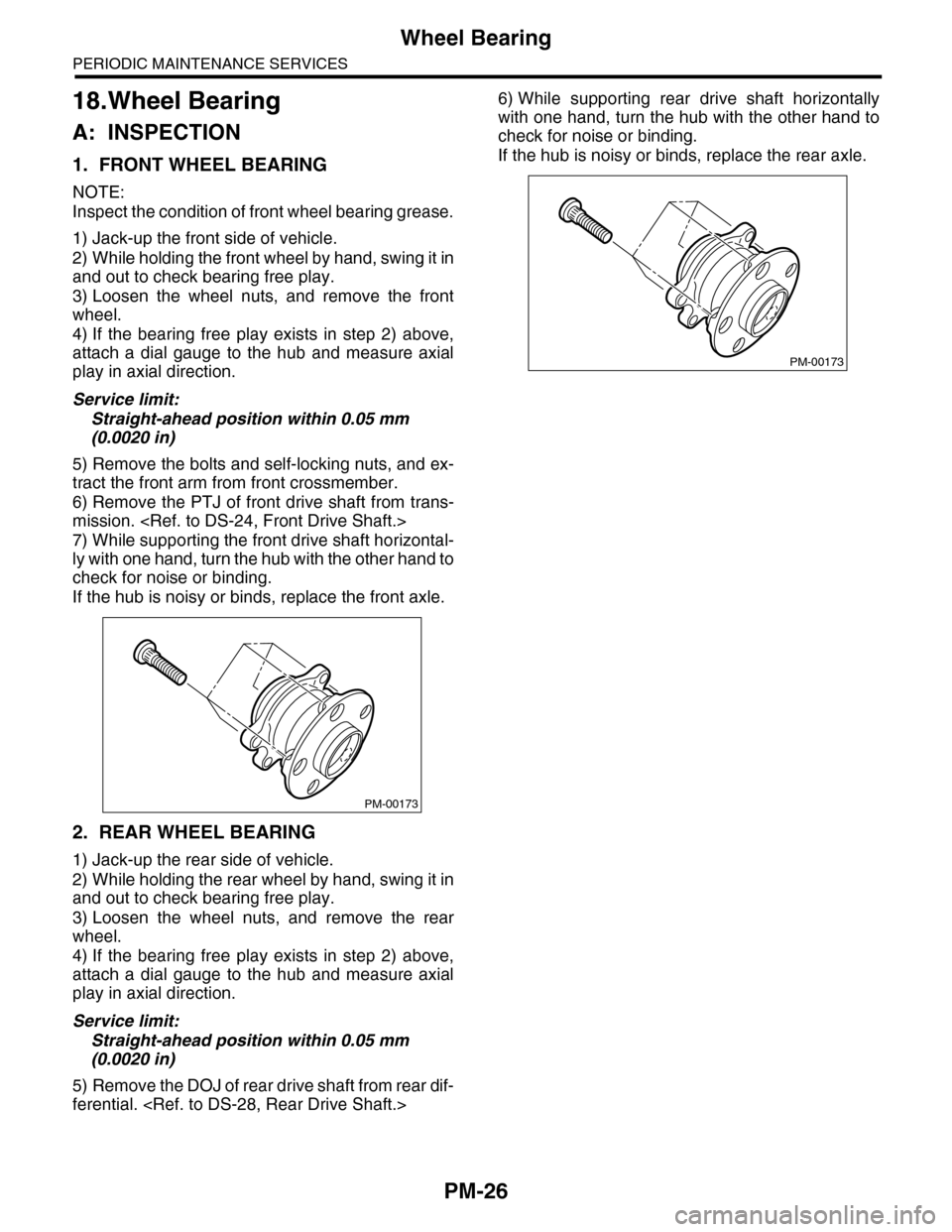
4) If the bearing free play exists in step 2) above,
attach a dial gauge to the hub and measure axial
play in axial direction.
Service limit:
Straight-ahead position within 0.05 mm
(0.0020 in)
5) Remove the bolts and self-locking nuts, and ex-
tract the front arm from front crossmember.
6) Remove the PTJ of front drive shaft from trans-
mission.
7) While supporting the front drive shaft horizontal-
ly with one hand, turn the hub with the other hand to
check for noise or binding.
If the hub is noisy or binds, replace the front axle.
2. REAR WHEEL BEARING
1) Jack-up the rear side of vehicle.
2) While holding the rear wheel by hand, swing it in
and out to check bearing free play.
3) Loosen the wheel nuts, and remove the rear
wheel.
4) If the bearing free play exists in step 2) above,
attach a dial gauge to the hub and measure axial
play in axial direction.
Service limit:
Straight-ahead position within 0.05 mm
(0.0020 in)
5) Remove the DOJ of rear drive shaft from rear dif-
ferential.
6) While supporting rear drive shaft horizontally
with one hand, turn the hub with the other hand to
check for noise or binding.
If the hub is noisy or binds, replace the rear axle.
PM-00173
PM-00173
Page 2012 of 2453
PM-29
Steering System (Power Steering)
PERIODIC MAINTENANCE SERVICES
21.Steering System (Power
Steering)
A: INSPECTION
1. STEERING WHEEL
1) Set the steering wheel in a straight-ahead posi-
tion, and check the wheel spokes to make sure
they are correctly set in their specified positions.
2) Lightly turn the steering wheel to the left and
right to determine the point where front wheels start
to move.
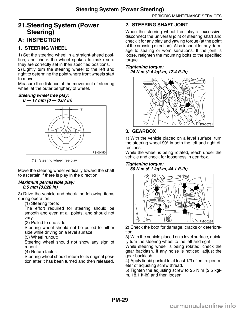
Measure the distance of the movement of steering
wheel at the outer periphery of wheel.
Steering wheel free play:
0 — 17 mm (0 — 0.67 in)
Move the steering wheel vertically toward the shaft
to ascertain if there is play in the direction.
Maximum permissible play:
0.5 mm (0.020 in)
3) Drive the vehicle and check the following items
during operation.
(1) Steering force:
The effort required for steering should be
smooth and even at all points, and should not
vary.
(2) Pulled to one side:
Steering wheel should not be pulled to either
side while driving on a level surface.
(3) Wheel runout:
Steering wheel should not show any sign of
runout.
(4) Return factor:
Steering wheel should return to its original posi-
tion after it has been turned and then released.
2. STEERING SHAFT JOINT
When the steering wheel free play is excessive,
disconnect the universal joint of steering shaft and
check it for any play and yawing torque (at the point
of the crossing direction). Also inspect for any dam-
age to sealing or worn serrations. If the joint is
loose, retighten the mounting bolts to the specified
torque.
Tightening torque:
24 N·m (2.4 kgf-m, 17.4 ft-lb)
3. GEARBOX
1) With the vehicle placed on a level surface, turn
the steering wheel 90° in both the left and right di-
rections.
While the wheel is being rotated, reach under the
vehicle and check for looseness in gearbox.
Tightening torque:
60 N·m (6.1 kgf-m, 44.1 ft-lb)
2) Check the boot for damage, cracks or deteriora-
tion.
3) With the vehicle placed on a level surface, quick-
ly turn the steering wheel to the left and right.
While steering wheel is being rotated, check the
gear backlash. If any noise is noticed, adjust the
gear backlash.
4) Apply liquid gasket to at least 1/3 of entire perim-
eter of adjusting screw thread.
5) Tighten the adjusting screw to 25 N·m (2.5 kgf-
m, 18.1 ft-lb) and then loosen.
(1) Steering wheel free play
(1)
PS-00450
PS-00731
PM-00295