Page 1517 of 2453

EN(H6DO)(diag)-356
Diagnostic Procedure with Diagnostic Trouble Code (DTC)
ENGINE (DIAGNOSTICS)
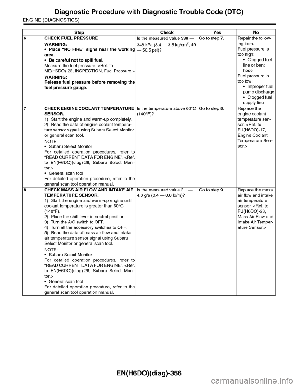
6CHECK FUEL PRESSURE
WARNING:•Place “NO FIRE” signs near the working
area.
•Be careful not to spill fuel.
Measure the fuel pressure.
ME(H6DO)-26, INSPECTION, Fuel Pressure.>
WARNING:Release fuel pressure before removing the
fuel pressure gauge.
Is the measured value 338 —
348 kPa (3.4 — 3.5 kg/cm2, 49
— 50.5 psi)?
Go to step 7.Repair the follow-
ing item.
Fuel pressure is
too high:
•Clogged fuel
line or bent
hose
Fuel pressure is
too low:
•Improper fuel
pump discharge
•Clogged fuel
supply line
7CHECK ENGINE COOLANT TEMPERATURE
SENSOR.
1) Start the engine and warm-up completely.
2) Read the data of engine coolant tempera-
ture sensor signal using Subaru Select Monitor
or general scan tool.
NOTE:•Subaru Select Monitor
For detailed operation procedures, refer to
“READ CURRENT DATA FOR ENGINE”.
to EN(H6DO)(diag)-26, Subaru Select Moni-
tor.>
•General scan tool
For detailed operation procedure, refer to the
general scan tool operation manual.
Is the temperature above 60°C
(140°F)?
Go to step 8.Replace the
engine coolant
temperature sen-
sor.
FU(H6DO)-17,
Engine Coolant
Te m p e r a t u r e S e n -
sor.>
8CHECK MASS AIR FLOW AND INTAKE AIR
TEMPERATURE SENSOR.
1) Start the engine and warm-up engine until
coolant temperature is greater than 60°C
(140°F).
2) Place the shift lever in neutral position.
3) Turn the A/C switch to OFF.
4) Turn all the accessory switches to OFF.
5) Read the data of mass air flow and intake
air temperature sensor signal using Subaru
Select Monitor or general scan tool.
NOTE:•Subaru Select Monitor
For detailed operation procedures, refer to
“READ CURRENT DATA FOR ENGINE”.
to EN(H6DO)(diag)-26, Subaru Select Moni-
tor.>
•General scan tool
For detailed operation procedure, refer to the
general scan tool operation manual.
Is the measured value 3.1 —
4.3 g/s (0.4 — 0.6 lb/m)?
Go to step 9.Replace the mass
air flow and intake
air temperature
sensor.
FU(H6DO)-23,
Mass Air Flow and
Intake Air Temper-
ature Sensor.>
Step Check Yes No
Page 1553 of 2453

EN(H6DO)(diag)-392
General Diagnostic Table
ENGINE (DIAGNOSTICS)
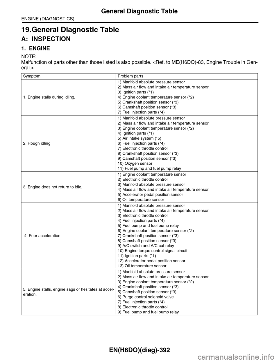
19.General Diagnostic Table
A: INSPECTION
1. ENGINE
NOTE:
Malfunction of parts other than those listed is also possible.
eral.>
Symptom Problem parts
1. Engine stalls during idling.
1) Manifold absolute pressure sensor
2) Mass air flow and intake air temperature sensor
3) Ignition parts (*1)
4) Engine coolant temperature sensor (*2)
5) Crankshaft position sensor (*3)
6) Camshaft position sensor (*3)
7) Fuel injection parts (*4)
2. Rough idling
1) Manifold absolute pressure sensor
2) Mass air flow and intake air temperature sensor
3) Engine coolant temperature sensor (*2)
4) Ignition parts (*1)
5) Air intake system (*5)
6) Fuel injection parts (*4)
7) Electronic throttle control
8) Crankshaft position sensor (*3)
9) Camshaft position sensor (*3)
10) Oxygen sensor
11) Fuel pump and fuel pump relay
3. Engine does not return to idle.
1) Engine coolant temperature sensor
2) Electronic throttle control
3) Manifold absolute pressure sensor
4) Mass air flow and intake air temperature sensor
5) Accelerator pedal position sensor
6) Oil temperature sensor
4. Poor acceleration
1) Manifold absolute pressure sensor
2) Mass air flow and intake air temperature sensor
3) Electronic throttle control
4) Fuel injection parts (*4)
5) Fuel pump and fuel pump relay
6) Engine coolant temperature sensor (*2)
7) Crankshaft position sensor (*3)
8) Camshaft position sensor (*3)
9) A/C switch and A/C cut relay
10) Engine torque control signal circuit
11) Ignition parts (*1)
12) Accelerator pedal position sensor
13) Oil temperature sensor
5. Engine stalls, engine sags or hesitates at accel-
eration.
1) Manifold absolute pressure sensor
2) Mass air flow and intake air temperature sensor
3) Engine coolant temperature sensor (*2)
4) Crankshaft position sensor (*3)
5) Camshaft position sensor (*3)
6) Purge control solenoid valve
7) Fuel injection parts (*4)
8) Electronic throttle control
9) Fuel pump and fuel pump relay
Page 1554 of 2453

EN(H6DO)(diag)-393
General Diagnostic Table
ENGINE (DIAGNOSTICS)
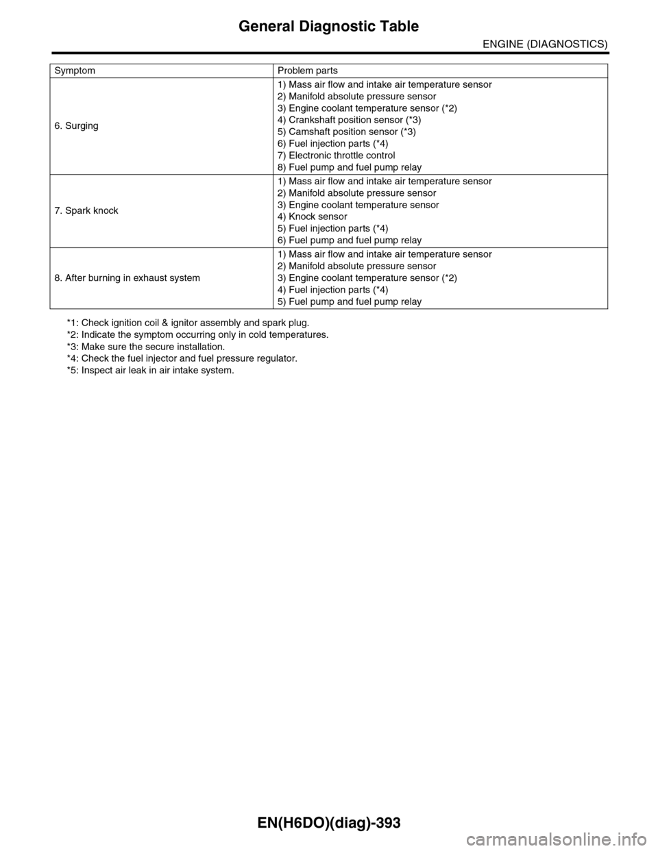
*1: Check ignition coil & ignitor assembly and spark plug.
*2: Indicate the symptom occurring only in cold temperatures.
*3: Make sure the secure installation.
*4: Check the fuel injector and fuel pressure regulator.
*5: Inspect air leak in air intake system.
6. Surging
1) Mass air flow and intake air temperature sensor
2) Manifold absolute pressure sensor
3) Engine coolant temperature sensor (*2)
4) Crankshaft position sensor (*3)
5) Camshaft position sensor (*3)
6) Fuel injection parts (*4)
7) Electronic throttle control
8) Fuel pump and fuel pump relay
7. Spark knock
1) Mass air flow and intake air temperature sensor
2) Manifold absolute pressure sensor
3) Engine coolant temperature sensor
4) Knock sensor
5) Fuel injection parts (*4)
6) Fuel pump and fuel pump relay
8. After burning in exhaust system
1) Mass air flow and intake air temperature sensor
2) Manifold absolute pressure sensor
3) Engine coolant temperature sensor (*2)
4) Fuel injection parts (*4)
5) Fuel pump and fuel pump relay
Symptom Problem parts
Page 1563 of 2453
FU(H6DO)-2
General Description
FUEL INJECTION (FUEL SYSTEMS)
1. General Description
A: SPECIFICATION
Fuel tankCapacity 64 2 (16.9 US gal, 14.1 Imp gal)
Location Rear floor bottom
Fuel pump
Ty p e I m p e l l e r
Shutoff discharge pressure550 — 850 kPa (5.61 — 8.67 kg/cm2, 79.8 — 123.3 psi)
Discharge rate155 2 (41 US gal, 34.1 Imp gal)/h or more
[12 V at 300 kPa (3.06 kg/cm2, 43.5 psi)]
Fuel filterIn-tank type
Page 1569 of 2453
FU(H6DO)-8
General Description
FUEL INJECTION (FUEL SYSTEMS)
(1) Fuel tank (11) Fuel tank protector LH (Rear) (20) Heat shield cover
(2) Fuel tank band RH (12) Clip (21) Fuel tank protector RH (Front)
(3) Fuel tank band LH (13) Evaporation hose (22) Fuel tank protector LH (Front)
(4) Delivery tube (14) Clamp
(5) Jet pump tube (15) Fuel filler hoseTightening torque: N·m (kgf-m, ft-lb)
(6) Retainer (16) Fuel pump upper plateT1: 4.4 (0.45, 3.2)
(7) Fuel sub level sensor gasket (17) Fuel pump ASSYT2: 9 (0.9, 6.6)
(8) Fuel sub level sensor (18) Fuel level sensorT3: 17.5 (1.78, 12.9)
(9) Fuel sub level sensor upper plate (19) Fuel pump gasketT4: 33 (3.4, 25)
(10) Bracket
Page 1576 of 2453
FU(H6DO)-15
Intake Manifold
FUEL INJECTION (FUEL SYSTEMS)
11) Connect the engine coolant hoses to throttle
body.
12) Connect the connector to throttle body.
13) Install the generator.
INSTALLATION, Generator.>
14) Install the air cleaner case and air intake cham-
ber.
Cleaner Case.>
TION, Air Intake Chamber.>
15) Install the fuse of fuel pump to main fuse box.
16) Connect the ground cable to the battery.
17) Install the collector cover.
C: DISASSEMBLY
1) Remove the engine harness from intake mani-
fold.
2) Remove the throttle body.
11, REMOVAL, Throttle Body.>
3) Remove the manifold absolute pressure sensor.
solute Pressure Sensor.>
4) Remove the purge control solenoid valve.
to EC(H6DO)-6, REMOVAL, Purge Control Sole-
noid Valve.>
5) Loosen the clamp which holds fuel injector pipe
to fuel hose, and then disconnect the pipe from fuel
hose.
6) Remove the bolts which install fuel pipes on in-
take manifold.
FU-02114
FU-02487FU-02124
FU-02125
FU-02126
Page 1595 of 2453
FU(H6DO)-34
Fuel Pump Relay
FUEL INJECTION (FUEL SYSTEMS)
18.Fuel Pump Relay
A: REMOVAL
1) Disconnect the ground cable from battery.
2) Remove the glove box.
AL, Glove Box.>
3) Remove the harness cover (A).
4) Disconnect the connector from fuel pump relay.
B: INSTALLATION
Install in the reverse order of removal.
FU-02092
(A)
FU-02407
Page 1597 of 2453
FU(H6DO)-36
Fuel Pump Control Unit
FUEL INJECTION (FUEL SYSTEMS)
20.Fuel Pump Control Unit
A: REMOVAL
1) Disconnect the ground cable from battery.
2) Remove the rear quarter trim.
REMOVAL, Rear Quarter Trim.>
3) Disconnect the connector from fuel pump control
unit.
4) Remove the fuel pump control unit.
B: INSTALLATION
Install in the reverse order of removal.
FU-02680