Page 721 of 2453
BR-7
General Description
BRAKE
4. FRONT BRAKE PIPES AND HOSE
(1) Front brake pipe ASSY (6) GasketTightening torque: N·m (kgf-m, ft-lb)
(2) Two-way connector (7)
VDC control module and hydraulic
control unit (VDCCM&H/U)
T1: 15 (1.5, 10.8)
(3) Front brake hose RHT2: 18 (1.8, 13.0)
(4) Front brake hose LH (8) BracketT3: 19 (1.9, 14.0)
(5) Clamp (9) Master cylinderT4: 33 (3.4, 24.3)
BR-00493
T1
T2
T4
T2
T2
T2
T4
T1
T3
(8)(2)
(3)
(5)
(6)
(4)
(7)
(6)
(5)
T3
T1
T1
(1)
(9)
T1
Page 760 of 2453

BVC(diag)-5
General Description
BRAKE VACUUM CONTROL (BVC) (DIAGNOSTICS)
3. General Description
A: CAUTION
1. SRS AIRBAG SYSTEM
Airbag system wiring harness is routed near the ABS wheel speed sensor and VDCCM&H/U.
CAUTION:
•All airbag system wiring harness and connectors are colored yellow. Do not use the electrical test
equipment on these circuits.
•Be careful not to damage the airbag system wiring harness.
B: INSPECTION
Before performing diagnosis, check the following items which might affect the brake vacuum control.
1. BATTERY
Measure the battery voltage and check electrolyte.
Standard voltage: 12 V or more
Specific gravity: 1.260 or more
2. BRAKE VACUUM HOSE
Make sure the brake vacuum hose is not cracked or loose.
C: PREPARATION TOOL
1. SPECIAL TOOL
2. GENERAL TOOL
ILLUSTRATION TOOL NUMBER DESCRIPTION REMARKS
18482AA010 CARTRIDGE Troubleshooting for the electrical system.
22771AA030 SUBARU SELECT
MONITOR KIT
Tr o u b l e s h o o t i n g f o r t h e e l e c t r i c a l s y s t e m .
TOOL NAME REMARKS
Circuit tester Used for measuring resistance, voltage and current.
Oscilloscope Used for measuring the sensor.
ST18482AA010
ST22771AA030
Page 1001 of 2453

VDC(diag)-9
General Description
VEHICLE DYNAMICS CONTROL (VDC) (DIAGNOSTICS)
3. General Description
A: CAUTION
1. SRS AIRBAG SYSTEM
Airbag system wiring harness is routed near the
ABS wheel speed sensor and VDCCM&H/U.
CAUTION:
•All airbag system wiring harness and con-
nectors are colored yellow. Do not use the elec-
trical test equipment on these circuits.
•Be careful not to damage the airbag system
wiring harness when servicing the ABS wheel
speed sensor and VDCCM&H/U.
B: INSPECTION
Before performing diagnosis, check the following
items which might affect VDC problems.
1. BATTERY
Measure the battery voltage and check electrolyte.
Standard voltage: 12 V or more
Specific gravity: 1.260 or more
2. GROUND
Check the tightening torque of ground (GB-7) bolt
of VDC.
Tightening torque:
13 N·m (1.3 kgf-m, 9.6 ft-lb)
3. BRAKE FLUID
1) Check the brake fluid level.
2) Check the brake fluid for leaks.
4. HYDRAULIC UNIT
Check the hydraulic unit.
•With brake tester
DRAULIC UNIT VDC OPERATION WITH BRAKE
TESTER, INSPECTION, VDC Control Module &
Hydraulic Control Unit (VDCCM&H/U).>
•Without brake tester
ING THE HYDRAULIC UNIT VDC OPERATION
USING A PRESSURE GAUGE, INSPECTION,
VDC Control Module & Hydraulic Control Unit (VD-
CCM&H/U).>
5. BRAKE DRAG
Check for brake drag.
6. BRAKE PAD AND ROTOR
Check the brake pad and rotor.
•Front
Pad.>
Rotor.>
•Rear
Pad.>
Rotor.>
7. TIRE
Check the tire specifications, tire wear and air pres-
sure.
Description.>
Page 1003 of 2453
VDC(diag)-11
Electrical Component Location
VEHICLE DYNAMICS CONTROL (VDC) (DIAGNOSTICS)
4. Electrical Component Location
A: LOCATION
(1) VDC control module & hydraulic
control unit (VDCCM&H/U)
(6) VDC indicator light (11) ABS wheel speed sensor
(7) VDC warning light and TCS OFF
indicator light
(12) Yaw rate & lateral G sensor
(2) Relay box (13) Data link connector
(3) Engine control module (ECM) (8) Steering angle sensor (14) Transmission control module
(TCM)(4) Brake warning light (EBD warning
light)
(9) TCS OFF switch
(10) Magnetic encoder (15) Stop light switch
(5) ABS warning light
(4)(5)(6)(7)
(8)
(1)
(2)
(3)
(15)
(14)
(12)
(13)
(11)(10)
(11)(10)
(9)
VDC00359
Page 1005 of 2453
VDC(diag)-13
Control Module I/O Signal
VEHICLE DYNAMICS CONTROL (VDC) (DIAGNOSTICS)
5. Control Module I/O Signal
A: ELECTRICAL SPECIFICATION
NOTE:
•Terminal numbers in VDCCM&H/U connector are shown in the figure.
•When the connector is removed from VDCCM&H/U, the ABS warning light, VDC warning light and TCS
OFF indicator light illuminate.
VDC00365
B310
2627284344252423
12131411109
201918171615
43218765
2122
40414245463938373433323130293536
Page 1007 of 2453

VDC(diag)-15
Control Module I/O Signal
VEHICLE DYNAMICS CONTROL (VDC) (DIAGNOSTICS)
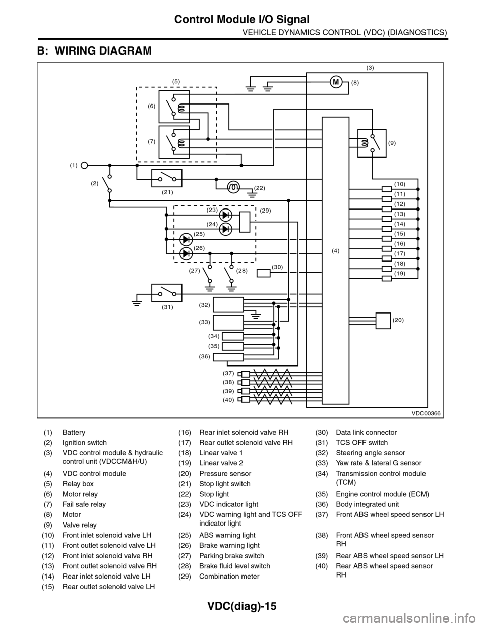
B: WIRING DIAGRAM
(1) Battery (16) Rear inlet solenoid valve RH (30) Data link connector
(2) Ignition switch (17) Rear outlet solenoid valve RH (31) TCS OFF switch
(3) VDC control module & hydraulic
control unit (VDCCM&H/U)
(18) Linear valve 1 (32) Steering angle sensor
(19) Linear valve 2 (33) Yaw rate & lateral G sensor
(4) VDC control module (20) Pressure sensor (34)
Tr a n s m i s s i o n c o n t r o l m o d u l e
(TCM)(5) Relay box (21) Stop light switch
(6) Motor relay (22) Stop light (35) Engine control module (ECM)
(7) Fail safe relay (23) VDC indicator light (36) Body integrated unit
(8) Motor (24) VDC warning light and TCS OFF
indicator light
(37)
Fr o nt A B S w he e l sp ee d se n so r L H
(9) Valve relay
(10) Front inlet solenoid valve LH (25) ABS warning light (38)
Fr o nt A B S w he e l sp e ed se n so r
RH(11) Front outlet solenoid valve LH (26) Brake warning light
(12) Front inlet solenoid valve RH (27) Parking brake switch (39) Rear ABS wheel speed sensor LH
(13) Front outlet solenoid valve RH (28) Brake fluid level switch (40) Rear ABS wheel speed sensor
RH(14) Rear inlet solenoid valve LH (29) Combination meter
(15) Rear outlet solenoid valve LH
VDC00366
M
(17)(4)(16)
(19)
(20)
(18)
(38)
(37)
(32)
(33)
(36)
(34)
(35)
(40)
(39)
(15)
(14)
(13)
(12)
(7)
(22)(21)
(31)
(23)(29)
(24)
(25)
(26)
(27) (28)(30)
(1)
(2)
(6)
(11)
(10)
(9)
(8)
(3)
(5)
Page 1009 of 2453
![SUBARU TRIBECA 2009 1.G Service Workshop Manual VDC(diag)-17
Subaru Select Monitor
VEHICLE DYNAMICS CONTROL (VDC) (DIAGNOSTICS)
2. READ CURRENT DATA
1) On the «Main Menu» display screen, select the {Each System Check} and press the [YES] key.
2) SUBARU TRIBECA 2009 1.G Service Workshop Manual VDC(diag)-17
Subaru Select Monitor
VEHICLE DYNAMICS CONTROL (VDC) (DIAGNOSTICS)
2. READ CURRENT DATA
1) On the «Main Menu» display screen, select the {Each System Check} and press the [YES] key.
2)](/manual-img/17/7322/w960_7322-1008.png)
VDC(diag)-17
Subaru Select Monitor
VEHICLE DYNAMICS CONTROL (VDC) (DIAGNOSTICS)
2. READ CURRENT DATA
1) On the «Main Menu» display screen, select the {Each System Check} and press the [YES] key.
2) On the «System Selection Menu» display screen, select the {Brake Control} and press the [YES] key.
3) Press the [YES] key after {VDC AWD AT} is displayed.
4) On the «Brake Control Diagnosis» display screen, select the {Current Data Display/Save}, and then press
the [YES] key.
5) On the «Display Menu» screen, select the data display method and press the [YES] key.
6) Using a scroll key, scroll the display screen up or down until necessary data is shown.
•A list of the support data is shown in the following table.
NOTE:
For details concerning operation procedure, refer to the “SUBARU SELECT MONITOR OPERATION MAN-
UAL”.
Display Contents to be monitored Unit of measure
FR Wheel SpeedWheel speed detected by front ABS wheel speed sensor RH is dis-
played.km/h or MPH
FL Wheel SpeedWheel speed detected by front ABS wheel speed sensor LH is dis-
played.km/h or MPH
RR Wheel SpeedWheel speed detected by rear ABS wheel speed sensor RH is dis-
played.km/h or MPH
RL Wheel SpeedWheel speed detected by rear ABS wheel speed sensor LH is dis-
played.km/h or MPH
Fr o nt / Re ar G S e ns o r Ve h ic le f r on t / re a r ac ce le ra t io n d e te c te d by G se n so r is d i sp layed .m/s2
Lateral G Sensor Vehicle lateral acceleration detected by G sensor is displayed.m/s2
IG power supply voltage Voltage supplied to VDCCM&H/U is displayed. V
Steering Angle Sensor Steering angle detected by steering angle sensor is displayed. deg
Ya w R a t e S e n s o r V e h i c l e a n g u l a r s p e e d d e t e c t e d b y y a w r a t e s e n s o r i s d i s p l a y e d . d e g / s
Pressure Sensor Brake fluid pressure detected by pressure sensor is displayed. bar
ABS Control Flag ABS control condition is displayed. ON or OFF
EBD Control Flag EBD control condition is displayed. ON or OFF
Brake Switch Brake ON/OFF is displayed. ON or OFF
ABS Warning Light ON operation of the ABS warning light is displayed. ON or OFF
EBD Warning Light ON operation of the EBD warning light is displayed. ON or OFF
Motor Relay Signal Motor relay operation signal is displayed. ON or OFF
Motor Relay Monitor Motor relay monitor signal is displayed. ON or OFF
TCS Control Flag TCS control condition is displayed. ON or OFF
Va l ve R e l ay S i g n a l Va l v e r e l ay o p e r a t i o n s i g n a l i s d i s p l ay e d . O N o r O F F
VDC Control Flag VDC control condition is displayed. ON or OFF
VDC Warning Light ON operation of the VDC warning light is displayed. ON or OFF
OFF Light ON/OFF condition of TCS OFF indicator light is displayed. ON or OFF
E/G Control Prohibited Flag Engine control command signal is displayed. 1 or 0
OFF Switch Signal Operation condition of TCS OFF switch is displayed. ON or OFF
Motor Fail Safe Relay Drive
SignalMotor fail safe relay drive signal is displayed. ON or OFF
Page 1011 of 2453
VDC(diag)-19
Subaru Select Monitor
VEHICLE DYNAMICS CONTROL (VDC) (DIAGNOSTICS)
B: INSPECTION
1. COMMUNICATION FOR INITIALIZING IMPOSSIBLE
DETECTING CONDITION:
Defective harness connector
TROUBLE SYMPTOM:
Communication is impossible between VDC and Subaru Select Monitor.
WIRING DIAGRAM:
MAIN SBF
SBF-6
NO.33
B310
E
E
32431
VDCCM & H/U
B402
12345678
910 11 12 13 14 15 16
BATTERY
IGNITIONSWITCH
DATA LINKCONNECTOR
B402
10
1
B310
1234
1516171819202122232425262728293031323334353637383940414245464344568910 11 12 13 147
VDC00368