Page 2397 of 2453

WI-113
Navigation System
WIRING SYSTEM
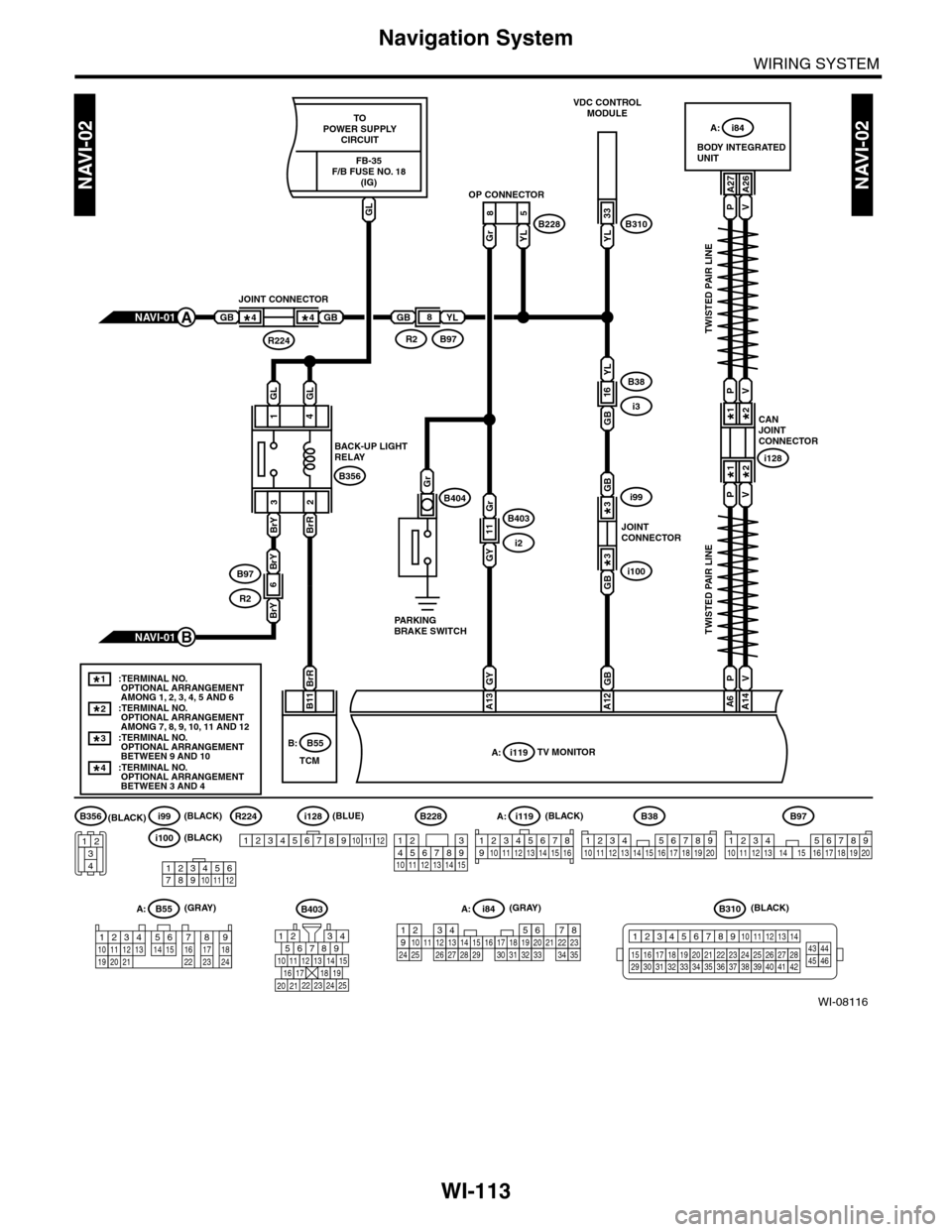
WI-08116
NAVI-02NAVI-02
PV
PV
123456789101112
i100(BLACK)
i99R224(BLACK)(BLACK)
(BLACK)(GRAY)
(BLUE)
YL
33
A27A26
85
GrYL
TWISTED PAIR LINE
TWISTED PAIR LINE
CANJOINTCONNECTOR
i128
1*
1*
2*
2*
B11
BODY INTEGRATEDUNIT
A: i84
VDC CONTROLMODULE
OP CONNECTOR
B310B228
A: i84
A: i119
1234567891011121415161718192021222324252627282930313233343513
PV
PV
A14A6
GB
A12
GYBrR
A13
GB
GBi100
i99
JOINTCONNECTOR
3*
3*
GB
YL
16B38
i3
GY
Gr
GB
11B403
i2
NAVI-01A
NAVI-01B
GB
JOINT CONNECTOR
R224
4*4*GBYL
B97R2
8
:TERMINAL NO. OPTIONAL ARRANGEMENT AMONG 1, 2, 3, 4, 5 AND 6:TERMINAL NO. OPTIONAL ARRANGEMENT AMONG 7, 8, 9, 10, 11 AND 12
1*
:TERMINAL NO. OPTIONAL ARRANGEMENT BETWEEN 9 AND 10
3*
:TERMINAL NO. OPTIONAL ARRANGEMENT BETWEEN 3 AND 4
4*
2*
i119TV MONITORA:B55B:
B38
1234 567891011 1213 14 15 16 17 18 19 20
B310
1234
1516171819202122232425262728293031323334353637383940414245464344568910 11 12 13 147
i128
123456789101112
B97
1234567891011 121316 17 18 19 201415
B228
131415
123456789101112
123 8910412 13 14 15 1656711
567821943
10
2422 23 25
11121314151617181920 21
B403(GRAY)A: B55
123410 11 1219 20 21135614 1578916 17 1822 23 24
(BLACK)B356
34
12
TCM
GLGL
4
BrRBrY 1
32
B356
B404Gr
BACK-UP LIGHTRELAY
PARKINGBRAKE SWITCH
BrY
BrY
6B97
R2
TOPOWER SUPPLYCIRCUIT
GL
FB-35F/B FUSE NO. 18(IG)
Page 2398 of 2453
WI-114
Navigation System
WIRING SYSTEM
WI-08117
NAVI-03NAVI-03
G
B1
i131AUDIO MODULE
1
RY
B2
2
BrW
B3
3
W
B6
6
GOr
B7
7
WL
B10
10
R
B11
11
L
B12
12
P
B17
17
LW
B18
18
YB
B19
19
BrY
GRYBrWWGOrWLRLPLWYBBrYYBr
B20
YBr
B9B8
2098
i112
123456
i112
Y
YJOINT CONNECTOR1*
Br2*
Br2*
1*
i120TV MONITORB:
:TERMINAL NO. OPTIONAL ARRANGEMENT AMONG 1, 2 AND 3
:TERMINAL NO. OPTIONAL ARRANGEMENT AMONG 4, 5 AND 6
1*
2*
i131
123 8910413 14 15 16567111217181920
i120B:
TWISTED PAIR LINE
TWISTED PAIR LINE
(BLACK)
(BLACK)
Page 2399 of 2453
WI-115
Navigation System
WIRING SYSTEM
WI-08118
NAVI-04NAVI-04
i118NAVIGATION SWITCH
W
1
WB
2
WR
3
WG
4
WL
5
BW
6
BR
7
BY
WWBWRWGWLBWBRBY
8
i121NAVIGATION SWITCH
12345678
i121
i118
12345678
(BLACK)
(BLACK)
Page 2443 of 2453

WI-159
Instrument Panel Wiring Harness
WIRING SYSTEM
59.Instrument Panel Wiring Harness
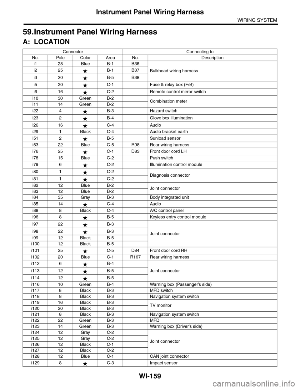
A: LOCATION
Connector Connecting to
No. Pole Color Area No. Description
i1 28 Blue B-1 B36
Bulkhead wiring harnessi2 25 B-1 B37
i3 20 B-5 B38
i5 20 C-1 Fuse & relay box (F/B)
i6 16 C-2 Remote control mirror switch
i10 30 Green B-2Combination meteri11 14 Green B-2
i22 4 B-3 Hazard switch
i23 2 B-4 Glove box illumination
i26 16 C-4 Audio
i29 1 Black C-4 Audio bracket earth
i51 2 B-5 Sunload sensor
i53 22 Blue C-5 R98 Rear wiring harness
i76 25 C-1 D83 Front door cord LH
i78 15 Blue C-2 Push switch
i79 6 C-2 Illumination control module
i80 1 C-2Diagnosis connectori81 1 C-2
i82 12 Blue B-2Joint connectori83 12 Blue B-2
i84 35 Gray B-3 Body integrated unit
i85 14 C-4 Audio
i88 8 Black C-4 A/C control panel
i96 8 B-5 Keyless entry control module
i97 22 B-3
Joint connectori98 22 B-3
i99 12 Black B-5
i100 12 Black B-5
i101 25 C-5 D84 Front door cord RH
i102 20 Blue C-1 R167 Rear wiring harness
i112 6 B-4
Joint connectori113 12 B-5
i114 12 B-5
i116 10 Green B-4 Warning box (Passenger’s side)
i117 8 Black B-3 MFD switch
i118 8 Black B-3 Navigation system switch
i119 16 Black B-3TV monitori120 20 Black B-3
i121 8 Black B-3 Navigation system switch
i122 22 Green B-3 MFD
i123 14 Green B-3 Warning box (Driver’s side)
i124 12 Gray C-2
Joint connectori125 12 Gray C-2
i126 12 Black C-1
i127 12 Black C-2
i128 12 Blue C-1 CAN joint connector
i129 8 C-3 Impact sensor
Page 2448 of 2453

WI-164
Rear Wiring Harness
WIRING SYSTEM
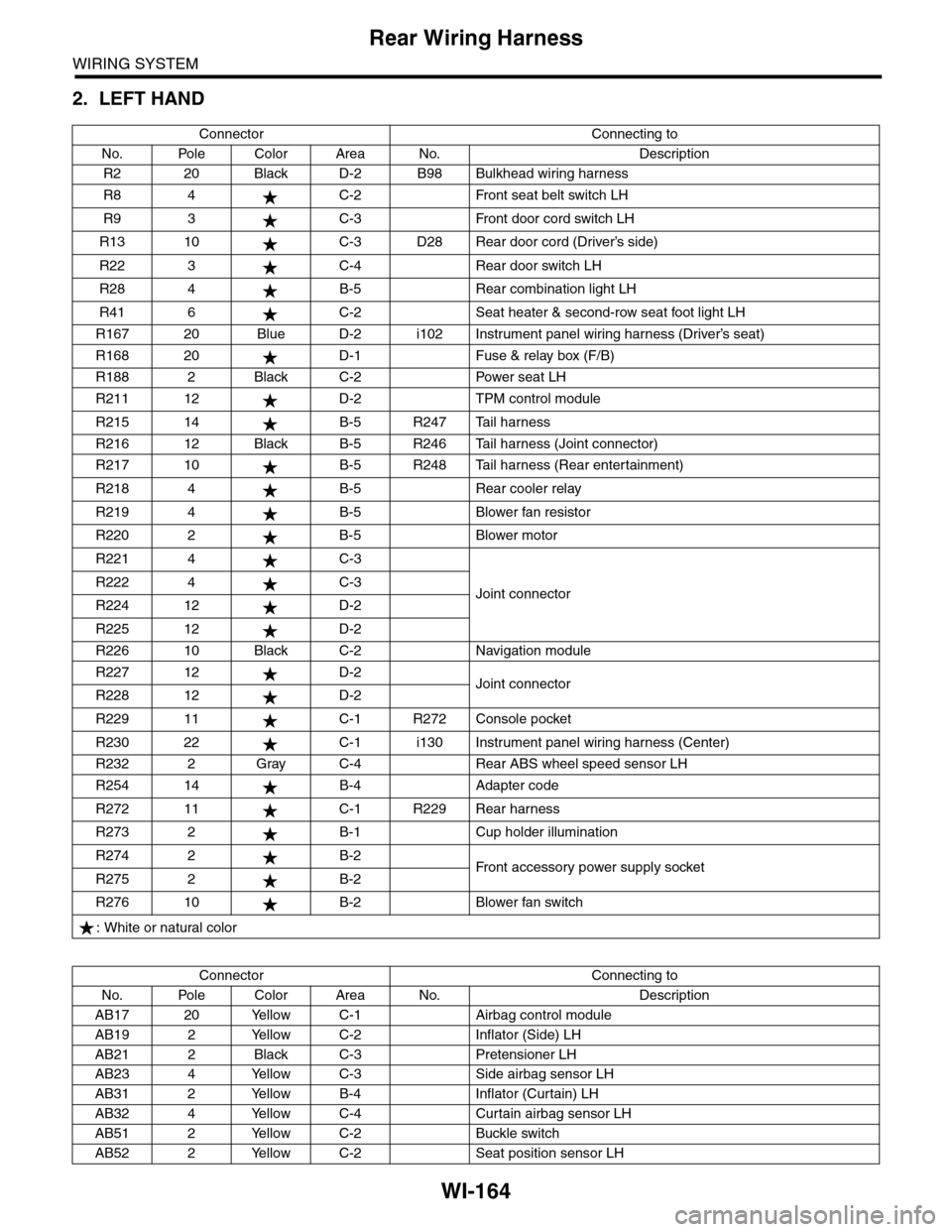
2. LEFT HAND
Connector Connecting to
No. Pole Color Area No. Description
R2 20 Black D-2 B98 Bulkhead wiring harness
R8 4 C-2 Front seat belt switch LH
R9 3 C-3 Front door cord switch LH
R13 10 C-3 D28 Rear door cord (Driver’s side)
R22 3 C-4 Rear door switch LH
R28 4 B-5 Rear combination light LH
R41 6 C-2 Seat heater & second-row seat foot light LH
R167 20 Blue D-2 i102 Instrument panel wiring harness (Driver’s seat)
R168 20 D-1 Fuse & relay box (F/B)
R188 2 Black C-2 Power seat LH
R211 12 D-2 TPM control module
R215 14 B-5 R247 Tail harness
R216 12 Black B-5 R246 Tail harness (Joint connector)
R217 10 B-5 R248 Tail harness (Rear entertainment)
R218 4 B-5 Rear cooler relay
R219 4 B-5 Blower fan resistor
R220 2 B-5 Blower motor
R221 4 C-3
Joint connectorR222 4 C-3
R224 12 D-2
R225 12 D-2
R226 10 Black C-2 Navigation module
R227 12 D-2Joint connectorR228 12 D-2
R229 11 C-1 R272 Console pocket
R230 22 C-1 i130 Instrument panel wiring harness (Center)
R232 2 Gray C-4 Rear ABS wheel speed sensor LH
R254 14 B-4 Adapter code
R272 11 C-1 R229 Rear harness
R273 2 B-1 Cup holder illumination
R274 2 B-2Fr o nt a cc es so r y p ower s up pl y s ocke tR275 2 B-2
R276 10 B-2 Blower fan switch
: White or natural color
Connector Connecting to
No. Pole Color Area No. Description
AB17 20 Yellow C-1 Airbag control module
AB19 2 Yellow C-2 Inflator (Side) LH
AB21 2 Black C-3 Pretensioner LH
AB23 4 Yellow C-3 Side airbag sensor LH
AB31 2 Yellow B-4 Inflator (Curtain) LH
AB32 4 Yellow C-4 Curtain airbag sensor LH
AB51 2 Yellow C-2 Buckle switch
AB52 2 Yellow C-2 Seat position sensor LH
Page:
< prev 1-8 9-16 17-24