2009 SUBARU TRIBECA horn
[x] Cancel search: hornPage 658 of 2453
SL-29
Security System
SECURITY AND LOCKS
NOTE:
Check the function setting of body integrated unit if any of the following symptoms appear.
•The horn does not sound even when the security system operates.
•The horn sounds when setting the security to ON using the keyless transmitter.
2. CHECK SECURITY SYSTEM CONDITION MEMORY
1) Remove the key from ignition switch.
2) Close all doors and the rear gate.
3) Open the front hood.
4) Press the LOCK button of transmitter, and then wait until the security indicator light flashes twice for 0.5
sec at intervals of 2 seconds.
5) Disconnect the ground cable from battery.
6) Connect the ground cable to the battery.
7) Check that the security indicator light blinks twice within 0.5 seconds at 2 seconds intervals. When it does
not blink, replace the body integrated unit.
3. SECURITY SYSTEM ON/OFF SETTING
1) Close all doors and rear gate, and sit down on the driver’s seat. Press the UNLOCK button of the keyless
transmitter.
2) Turn the ignition switch ON.
3) Push the centralized door lock switch down and open the driver’s side door at the same time, and hold in
this condition for 10 seconds.
4) If the security system is ON, it will turn OFF. If OFF, it will turn ON.
Page 661 of 2453

SL-32
Security System
SECURITY AND LOCKS
6. CHECK SECURITY INDICATOR LIGHT CIRCUIT.
7. CHECK HORN
Step Check Yes No
1CHECK SECURITY INDICATOR LIGHT.
1) Turn the ignition switch to OFF.
2) Disconnect the harness connector of body
integrated unit.
3) Connect the resistor (100 Ω) between the
body integrated unit harness connector termi-
nal (i84) No. 33 and chassis ground.
Connector & terminal
(i84) No. 33 — Chassis ground:
Does the security indicator
light illuminate?
Check the body
integrated unit.
Diagnostic Proce-
dure.>
Go to step 2.
2CHECK POWER SUPPLY FOR SECURITY
INDICATOR LIGHT.
1) Disconnect the connector from warning
box.
2) Measure the voltage between warning box
harness connector terminal and chassis
ground.
Connector & terminal
(i116) No. 1 (+) — Chassis ground (–):
Is the voltage more than 10 V? Go to step 3.Check the harness
for open or shor t
circuits between
warning box and
fuse.
3CHECK SECURITY INDICATOR LIGHT CIR-
CUIT.
Measure the resistance between the warning
box harness connector terminal and security
control unit harness connector terminal.
Connector & terminal
(i116) No. 2 — (i84) No. 33:
Is the resistance less than 10
Ω?
Replace the warn-
ing box.
Box.>
Check the harness
for open or shor t
circuits between
warning box and
body integrated
unit.
Step Check Yes No
1CHECK HORN OPERATION.
Check the horn sounds when the horn switch
is pushed.
Does the horn sound? Go to step 2.Check the horn cir-
cuit.
2CHECK OUTPUT TO HORN RELAY.
1) Connect the Subaru Select Monitor to data
link connector.
2) Turn the ignition switch to ON.
3) Select {Integ. unit} from main menu.
4) Select {Function Check}.
5) Select {Horn Output} and execute
Does the horn sound? Horn circuit is OK. Go to step 3.
3CHECK HORN RELAY CIRCUIT.
1) Turn the ignition switch to OFF.
2) Disconnect the harness connector of body
integrated unit.
3) Disconnect the main fuse box harness con-
nector (B186).
4) Measure the resistance between harness
connector terminals.
Connector & terminal
(B280) No. 11 — (B186) No. 1:
Is the resistance less than 10
Ω?
Check the body
integrated unit.
Diagnostic Proce-
dure.>
Repair the har-
ness.
Page 2299 of 2453
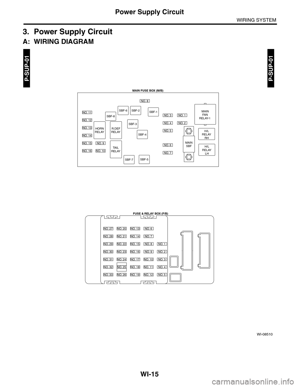
WI-15
Power Supply Circuit
WIRING SYSTEM
3. Power Supply Circuit
A: WIRING DIAGRAM
WI-08510
P-SUP-01P-SUP-01
MAIN FUSE BOX (M/B)
FUSE & RELAY BOX (F/B)
H/LRELAYRH
MAINFANRELAY-1
MAINSBFH/LRELAYLH
NO. 8
NO. 11
NO. 12
NO. 13
NO. 14
NO. 15
NO. 16
NO. 27
NO. 28
NO. 29
NO. 30
NO. 31
NO. 32
NO. 33
NO. 20
NO. 21
NO. 22
NO. 23
NO. 24
NO. 25
NO. 26
NO. 13
NO. 14
NO. 15
NO. 16
NO. 17
NO. 18
NO. 19
NO. 6
NO. 7
NO. 8
NO. 9
NO. 10
NO. 11
NO. 12
NO. 1
NO. 2
NO. 3
NO. 4
NO. 5
NO. 9
NO. 10
NO. 3
NO. 4
NO. 1
NO. 2
NO. 5
NO. 6
NO. 7
SBF-8
SBF-6SBF-2
SBF-3
SBF-4
SBF-7SBF-5
SBF-1
HORNRELAYR.DEFRELAY
TAILRELAY
Page 2301 of 2453
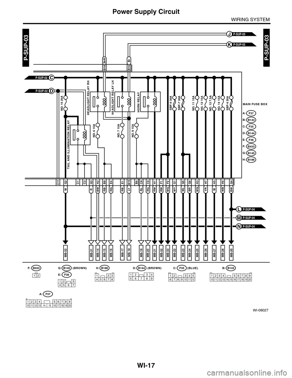
WI-17
Power Supply Circuit
WIRING SYSTEM
WI-08027
P-SUP-03P-SUP-03
WB
H6
W
H5G4
MAIN FUSE BOX
P-SUP-05K
P-SUP-05J
NO. 14 15ANO. 13 7.5ANO. 12 15ANO. 11 15ANO. 15 20A
NO. 6 15A
SBF-4 30ASBF-7 30ASBF-5 30A
BWWG
H3
BR
G6H7
YRWY
G1G5F2F1
WL
BrBrR
B18B16
B145G:B186H:(BROWN)B144D:(BLUE)F35C:
123456781234567891011121234 567891011 12 13 1415 16 17 18 19 20
B:B143
NO. 7 15ANO. 9 15A
TAIL AND ILLUMINATION RELAY
F37A:
B143B:
F35C:
B144D:
F36E:
B433F:
B145G:
B186H:
RW
H1B6
RL
C8
RG
C9B15
RB
E1C1C2
R
G3H2
RB
B8
RG
E4
W
G2C11
1234567
157628349
P-SUP-02C
P-SUP-02D
MB-21MB-22MB-26MB-25MB-24MB-33MB-27MB-32MB-28MB-19MB-14MB-23MB-32
WGRW
MB-31MB-18MB-17MB-16MB-15MB-20MB-30
P-SUP-04N
P-SUP-04M
P-SUP-04L
HEADLIGHT RELAY RHHEADLIGHT RELAY LHHORN RELAY
LYBW
F36E:
A:F37
1234 5678910 11 12 13 14 15 16 17 18 19 20
(BROWN)B433
12
F:
Page 2304 of 2453
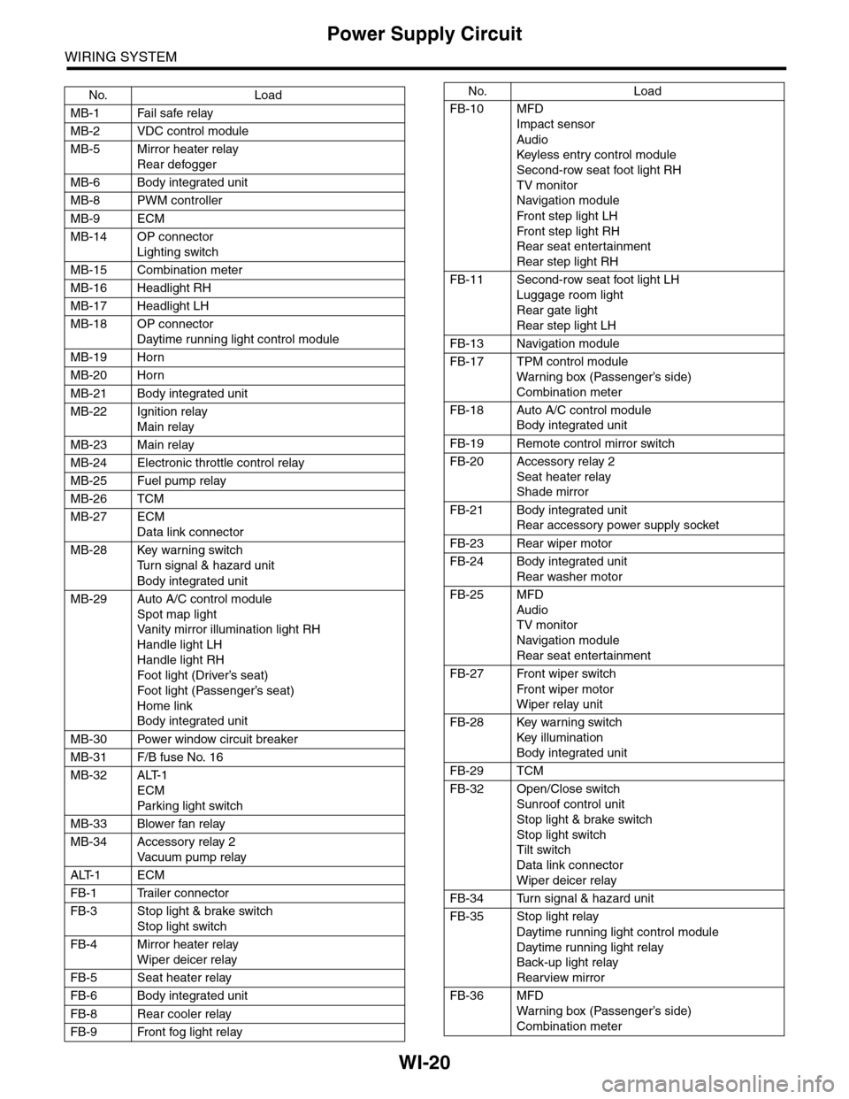
WI-20
Power Supply Circuit
WIRING SYSTEM
No. Load
MB-1 Fail safe relay
MB-2 VDC control module
MB-5 Mirror heater relay
Rear defogger
MB-6 Body integrated unit
MB-8 PWM controller
MB-9 ECM
MB-14 OP connector
Lighting switch
MB-15 Combination meter
MB-16 Headlight RH
MB-17 Headlight LH
MB-18 OP connector
Daytime running light control module
MB-19 Horn
MB-20 Horn
MB-21 Body integrated unit
MB-22 Ignition relay
Main relay
MB-23 Main relay
MB-24 Electronic throttle control relay
MB-25 Fuel pump relay
MB-26 TCM
MB-27 ECM
Data link connector
MB-28 Key warning switch
Tu r n s i g n a l & h a z a r d u n i t
Body integrated unit
MB-29 Auto A/C control module
Spot map light
Va n i t y m i r r o r i l l u m i n a t i o n l i g h t R H
Handle light LH
Handle light RH
Foot light (Driver’s seat)
Foot light (Passenger’s seat)
Home link
Body integrated unit
MB-30 Power window circuit breaker
MB-31 F/B fuse No. 16
MB-32 ALT-1
ECM
Par king light switch
MB-33 Blower fan relay
MB-34 Accessory relay 2
Va c u u m p u m p r e l ay
ALT-1 ECM
FB-1 Trailer connector
FB-3 Stop light & brake switch
Stop light switch
FB-4 Mirror heater relay
Wiper deicer relay
FB-5 Seat heater relay
FB-6 Body integrated unit
FB-8 Rear cooler relay
FB-9 Front fog light relay
FB-10 MFD
Impact sensor
Audio
Keyless entr y control module
Second-row seat foot light RH
TV monitor
Navigation module
Fr o n t s te p li gh t LH
Fr o n t s te p li gh t RH
Rear seat entertainment
Rear step light RH
FB-11 Second-row seat foot light LH
Luggage room light
Rear gate light
Rear step light LH
FB-13 Navigation module
FB-17 TPM control module
War ning box (Passenger’s side)
Combination meter
FB-18 Auto A/C control module
Body integrated unit
FB-19 Remote control mirror switch
FB-20 Accessory relay 2
Seat heater relay
Shade mirror
FB-21 Body integrated unit
Rear accessory power supply socket
FB-23 Rear wiper motor
FB-24 Body integrated unit
Rear washer motor
FB-25 MFD
Audio
TV monitor
Navigation module
Rear seat entertainment
FB-27 Front wiper switch
Fr o n t wi p er mo t or
Wiper relay unit
FB-28 Key warning switch
Key illumination
Body integrated unit
FB-29 TCM
FB-32 Open/Close switch
Sunroof control unit
Stop light & brake switch
Stop light switch
Tilt switch
Data link connector
Wiper deicer relay
FB-34 Turn signal & hazard unit
FB-35 Stop light relay
Daytime running light control module
Daytime running light relay
Back-up light relay
Rearview mirror
FB-36 MFD
War ning box (Passenger’s side)
Combination meter
No. Load
Page 2407 of 2453
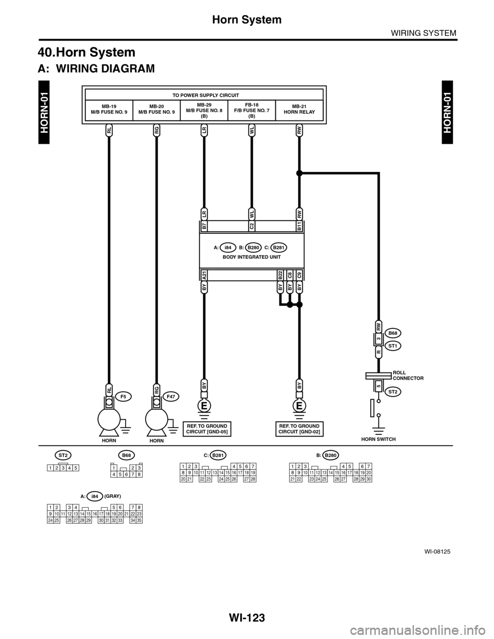
WI-123
Horn System
WIRING SYSTEM
40.Horn System
A: WIRING DIAGRAM
WI-08125
HORN-01HORN-01RLRGLRWL
MB-19M/B FUSE NO. 9MB-20M/B FUSE NO. 9MB-29M/B FUSE NO. 8(B)
FB-18F/B FUSE NO. 7(B)
MB-21HORN RELAY
TO POWER SUPPLY CIRCUIT
B68
ST1
ST2
R
RWWL
BYBYBY
3
5
B11C2C2
C9C8B22
BY
A21
LR
B7
BODY INTEGRATED UNIT
i84A:B280B:B281C:
HORN SWITCH
ROLLCONNECTOR
BY
HORNHORN
RGRLF47F5
A: i84
1234567891011121415161718192021222324252627282930313233343513
B68
32187654567821943102422 23 25111213141526 27 281617181920 21
B281C:
5467821931022 23111213141524 25 26 2716171828 29192021 30
B280B:
REF. TO GROUNDCIRCUIT [GND-05]
BY
REF. TO GROUNDCIRCUIT [GND-02]
RW
ST2
12345
RW
(GRAY)
Page 2425 of 2453
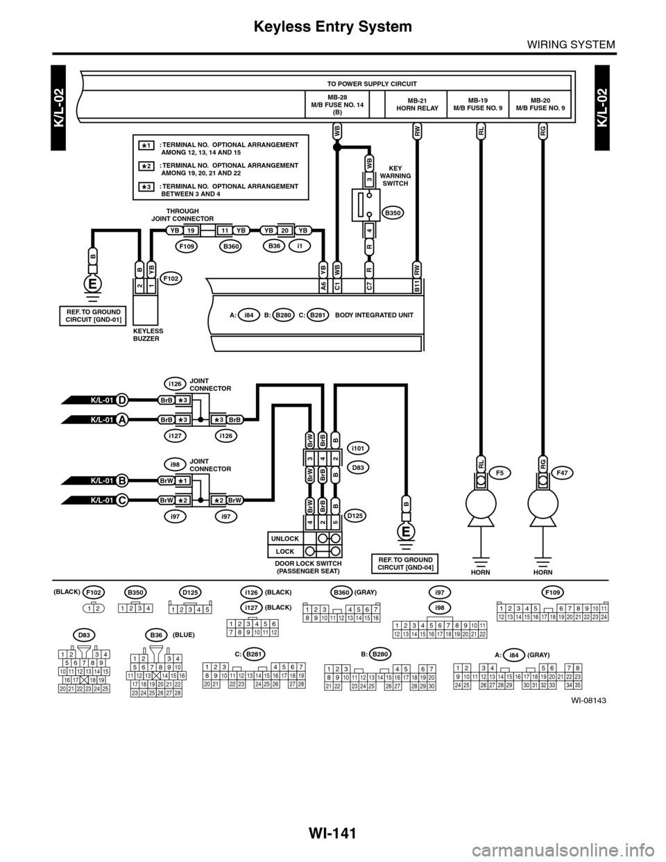
WI-141
Keyless Entry System
WIRING SYSTEM
K/L-02K/L-02
WI-08143
F5F47
RGRL
RW
B11
B: B280
RW
RGRL
5467821931022 23111213141524 25 26 2716171828 29192021 30
B280B:
D125
B
i101
D83
D125
12345
D83
567821943
10
2422 23 25
11121314151617181920 21
K/L-01B
K/L-01C
B350
WB
3
R
4
WB
R
C7
WB
C1F102
B360F109i1B36
2
B
19
1
YB
YBYBYB2011
B350
1234
F102
12
F109
3412 8910 1112 13 14 15 16 17 18 19 20 21 22 23 24567
56782194310
242223 252726 28
11121314151617181920 21
567821943102422 23 25111213141526 27 281617181920 21
B281C:A:i84
1234567891011121415161718192021222324252627282930313233343513
YB
YB
A6
A: i84C: B281
HORN HORN
TO POWER SUPPLY CIRCUIT
MB-19M/B FUSE NO. 9MB-20M/B FUSE NO. 9
BODY INTEGRATED UNIT
MB-21HORN RELAY
REF. TO GROUNDCIRCUIT [GND-04]DOOR LOCK SWITCH(PASSENGER SEAT)
i97i97
i98JOINTCONNECTOR
KEYLESSBUZZER
THROUGHJOINT CONNECTOR
KEYWARNINGSWITCH
MB-28M/B FUSE NO. 14(B)
(GRAY)
(GRAY)
B360
12345678910111213141516
BrW
BrW
BrW2*
1*
2*
K/L-01D
K/L-01A
i127i126
i126JOINTCONNECTOR
BrB
BrB
BrB3*
3*
3*
B
REF. TO GROUNDCIRCUIT [GND-01]
123456789101112
i127(BLACK)
(BLACK)i126(BLACK)
B36(BLUE)
i98
i97
12345678910111213141516171819202122
: TERMINAL NO. OPTIONAL ARRANGEMENT AMONG 12, 13, 14 AND 15
: TERMINAL NO. OPTIONAL ARRANGEMENT AMONG 19, 20, 21 AND 22
1*
2*
: TERMINAL NO. OPTIONAL ARRANGEMENT BETWEEN 3 AND 43*
24
BrWBrB
5
B
BrWBrBB
BrWBrBB
UNLOCK
LOCK
432
Page 2428 of 2453
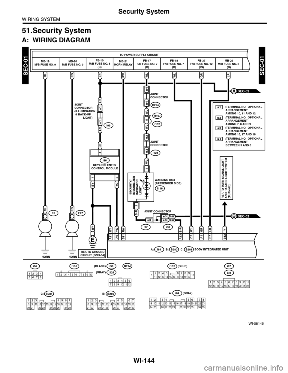
WI-144
Security System
WIRING SYSTEM
51.Security System
A: WIRING DIAGRAM
WI-08146
SEC-01SEC-01
SEC-02B
HORNHORN
F5F47
TO POWER SUPPLY CIRCUIT
MB-19M/B FUSE NO. 9MB-20M/B FUSE NO. 9FB-10M/B FUSE NO. 8(B)
FB-17F/B FUSE NO. 7(B)
FB-18F/B FUSE NO. 7 (B)
FB-37F/B FUSE NO. 12(IG)
MB-29M/B FUSE NO. 8 (B)
RGLRWLWLGRLRRL
73
LR
LR
JOINTCONNECTOR(ILLUMINATION & BACK-UP LIGHT)
KEYLESS ENTRYCONTROL MODULE
i99
LR
4
i96
BY
BYYG
A9
RW
B11
BY
A21
BrR
A33
WL
WL
R167
i102
WL
C2
GR
A1
LR
B7
Y
B12
BrR
2
1
SECURITY/IMMOBILIZERINDICATORLIGHTREF. TO TURN SIGNAL LIGHTAND HAZARD LIGHT SYSTEM[TURN-01]
BODY INTEGRATED UNITA: i84B: B280C: B281
WARNING BOX(PASSENGER SIDE)
i116YG
RW
RGRL
i96
12345678
567821943102422 23 25111213141526 27 281617181920 21
B281C:
5467821931022 23111213141524 25 26 2716171828 29192021 30
B280B:A: i84
1234567891011121415161718192021222324252627282930313233343513
REF. TO GROUNDCIRCUIT [GND-04]
SEC-02A
MB-21HORN RELAY
5
JOINTCONNECTOR
i124
2*
2*
1*
1*
JOINTCONNECTOR
R224
4*
4*
WL
BrWBrW
JOINT CONNECTOR
i97i98
3*
3*3*
: TERMINAL NO. OPTIONAL ARRANGEMENT AMONG 7, 8 AND 9: TERMINAL NO. OPTIONAL ARRANGEMENT AMONG 16, 17 AND 18
2*
: TERMINAL NO. OPTIONAL ARRANGEMENT AMONG 10, 11 AND 12
1*
3*
: TERMINAL NO. OPTIONAL ARRANGEMENT BETWEEN 5 AND 6
4*
1234567891413121110151617181920
i102(BLUE)
123456789101112
R224
i124(GRAY)
(GRAY)
i99(BLACK)i116
12345678910i98
i97
12345678910111213141516171819202122