2009 SUBARU TRIBECA fuel cap
[x] Cancel search: fuel capPage 1602 of 2453
FU(H6DO)-41
Fuel Filler Pipe
FUEL INJECTION (FUEL SYSTEMS)
23.Fuel Filler Pipe
A: REMOVAL
WARNING:
•Place “NO FIRE” signs near the working area.
•Be careful not to spill fuel on the floor.
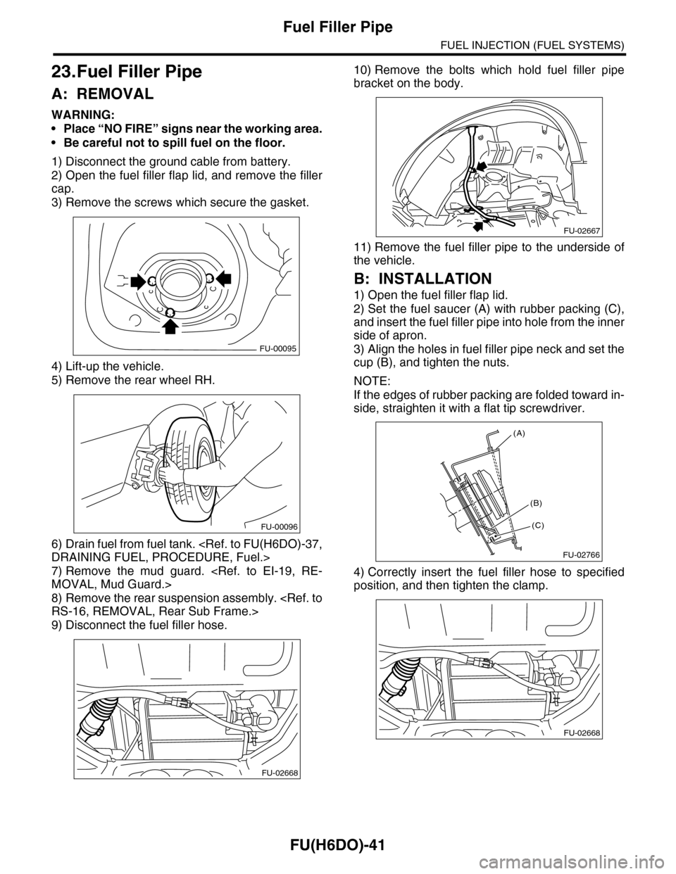
1) Disconnect the ground cable from battery.
2) Open the fuel filler flap lid, and remove the filler
cap.
3) Remove the screws which secure the gasket.
4) Lift-up the vehicle.
5) Remove the rear wheel RH.
6) Drain fuel from fuel tank.
7) Remove the mud guard.
8) Remove the rear suspension assembly.
9) Disconnect the fuel filler hose.
10) Remove the bolts which hold fuel filler pipe
bracket on the body.
11) Remove the fuel filler pipe to the underside of
the vehicle.
B: INSTALLATION
1) Open the fuel filler flap lid.
2) Set the fuel saucer (A) with rubber packing (C),
and insert the fuel filler pipe into hole from the inner
side of apron.
3) Align the holes in fuel filler pipe neck and set the
cup (B), and tighten the nuts.
NOTE:
If the edges of rubber packing are folded toward in-
side, straighten it with a flat tip screwdriver.
4) Correctly insert the fuel filler hose to specified
position, and then tighten the clamp.
FU-00095
FU-00096
FU-02668
FU-02667
FU-02766
(A)
(C)
(B)
FU-02668
Page 1609 of 2453
FU(H6DO)-48
Fuel Delivery, Return and Evaporation Lines
FUEL INJECTION (FUEL SYSTEMS)
28.Fuel Delivery, Return and Evaporation Lines
A: REMOVAL
1) Set the vehicle on a lift.
2) Release the fuel pressure.
3) Open the fuel filler flap lid, and remove the fuel filler cap.
4) Remove the floor mat.
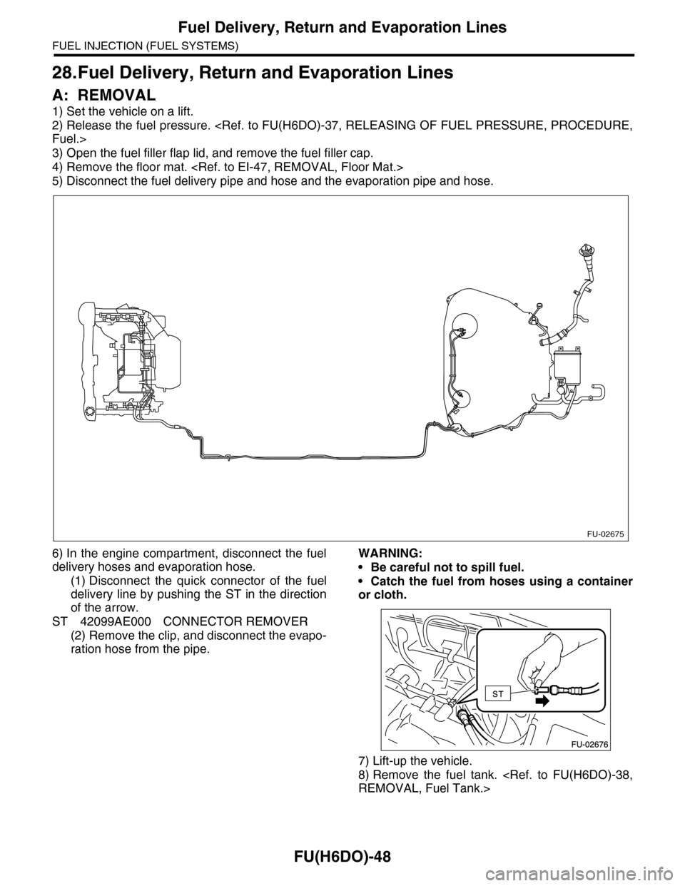
5) Disconnect the fuel delivery pipe and hose and the evaporation pipe and hose.
6) In the engine compartment, disconnect the fuel
delivery hoses and evaporation hose.
(1) Disconnect the quick connector of the fuel
delivery line by pushing the ST in the direction
of the arrow.
ST 42099AE000 CONNECTOR REMOVER
(2) Remove the clip, and disconnect the evapo-
ration hose from the pipe.
WARNING:
•Be careful not to spill fuel.
•Catch the fuel from hoses using a container
or cloth.
7) Lift-up the vehicle.
8) Remove the fuel tank.
FU-02675
Page 1618 of 2453
GD(H6DO)-6
List of Diagnostic Trouble Code (DTC)
GENERAL DESCRIPTION
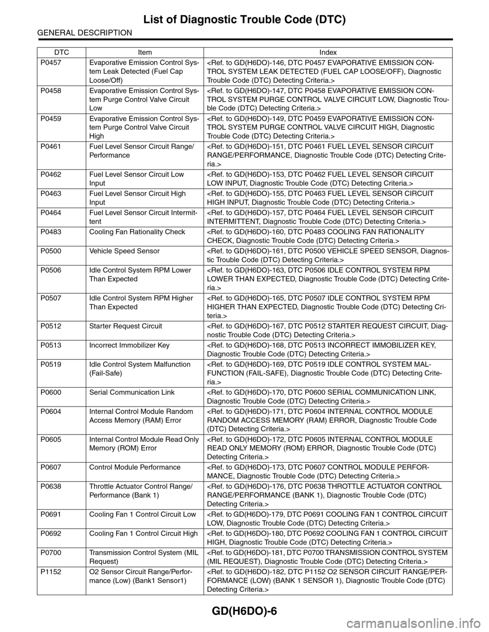
P0457 Evaporative Emission Control Sys-
tem Leak Detected (Fuel Cap
Loose/Off)
Tr o u b l e C o d e ( D T C ) D e t e c t i n g C r i t e r i a . >
P0458 Evaporative Emission Control Sys-
tem Purge Control Valve Circuit
Low
ble Code (DTC) Detecting Criteria.>
P0459 Evaporative Emission Control Sys-
tem Purge Control Valve Circuit
High
Tr o u b l e C o d e ( D T C ) D e t e c t i n g C r i t e r i a . >
P0461 Fuel Level Sensor Circuit Range/
Per fo r m an ce
ria.>
P0462 Fuel Level Sensor Circuit Low
Input
P0463 Fuel Level Sensor Circuit High
Input
P0464 Fuel Level Sensor Circuit Intermit-
tent
P0483 Cooling Fan Rationality Check
P0500 Vehicle Speed Sensor
P0506 Idle Control System RPM Lower
Than Expected
ria.>
P0507 Idle Control System RPM Higher
Than Expected
teria.>
P0512 Starter Request Circuit
P0513 Incorrect Immobilizer Key
P0519 Idle Control System Malfunction
(Fail-Safe)
ria.>
P0600 Serial Communication Link
P0604 Internal Control Module Random
Access Memory (RAM) Error
(DTC) Detecting Criteria.>
P0605 Internal Control Module Read Only
Memory (ROM) Error
Detecting Criteria.>
P0607 Control Module Performance
P0638 Throttle Actuator Control Range/
Per fo r m an ce ( B an k 1 )
Detecting Criteria.>
P0691 Cooling Fan 1 Control Circuit Low
P0692 Cooling Fan 1 Control Circuit High
P0700 Transmission Control System (MIL
Request)
P1152 O2 Sensor Circuit Range/Perfor-
mance (Low) (Bank1 Sensor1)
Detecting Criteria.>
DTC Item Index
Page 1741 of 2453
GD(H6DO)-129
Diagnostic Trouble Code (DTC) Detecting Criteria
GENERAL DESCRIPTION
3. GENERAL DRIVING CYCLE
0.04-inch Diagnosis
Perform the diagnosis only once in 851 seconds or more after starting the engine, at a constant speed of 32
km/h (20 MPH) or more.
Pay attention to the fuel temperature and fuel level.
0.02-inch Diagnosis
Perform the diagnosis after 120 seconds or more after starting the engine, at a constant engine RPM of 30
km/h (19 MPH) or higher, to judge as NG or OK.
If OK/NG judgment is not possible, repeat the diagnosis.
Pay attention to the fuel temperature and fuel level.
4. DIAGNOSTIC METHOD
0.04-inch Diagnosis
Mode Z: (Purge control solenoid valve opening failure diagnosis)
When performing the leakage diagnosis of the EVAP system, the purge control solenoid valve must operate
properly. Therefore, mode Z is used to diagnose a stuck open condition of the purge control solenoid valve
by monitoring the tank pressure.
Note that if a purge control solenoid valve stuck open fault is detected, the EVAP system leakage diagnosis
is cancelled.
Purge Control Solenoid Valve Stuck Open Diagnosis
DTC
P0457 Evaporative Emission Control System Leak Detected (Fuel Cap Loose/Off)
Diagnostic method
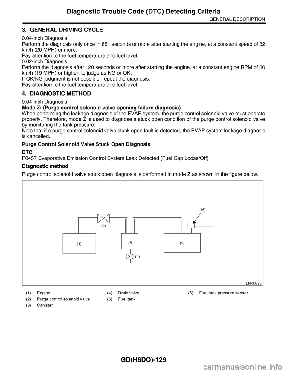
Purge control solenoid valve stuck open diagnosis is performed in mode Z as shown in the figure below.
(1) Engine (4) Drain valve (6) Fuel tank pressure sensor
(2) Purge control solenoid valve (5) Fuel tank
(3) Canister
EN-03723
(2)
(1)(3)
(4)
(5)
(6)
Page 1742 of 2453
GD(H6DO)-130
Diagnostic Trouble Code (DTC) Detecting Criteria
GENERAL DESCRIPTION
Purge Control Solenoid Valve Function Diagnosis
DTC
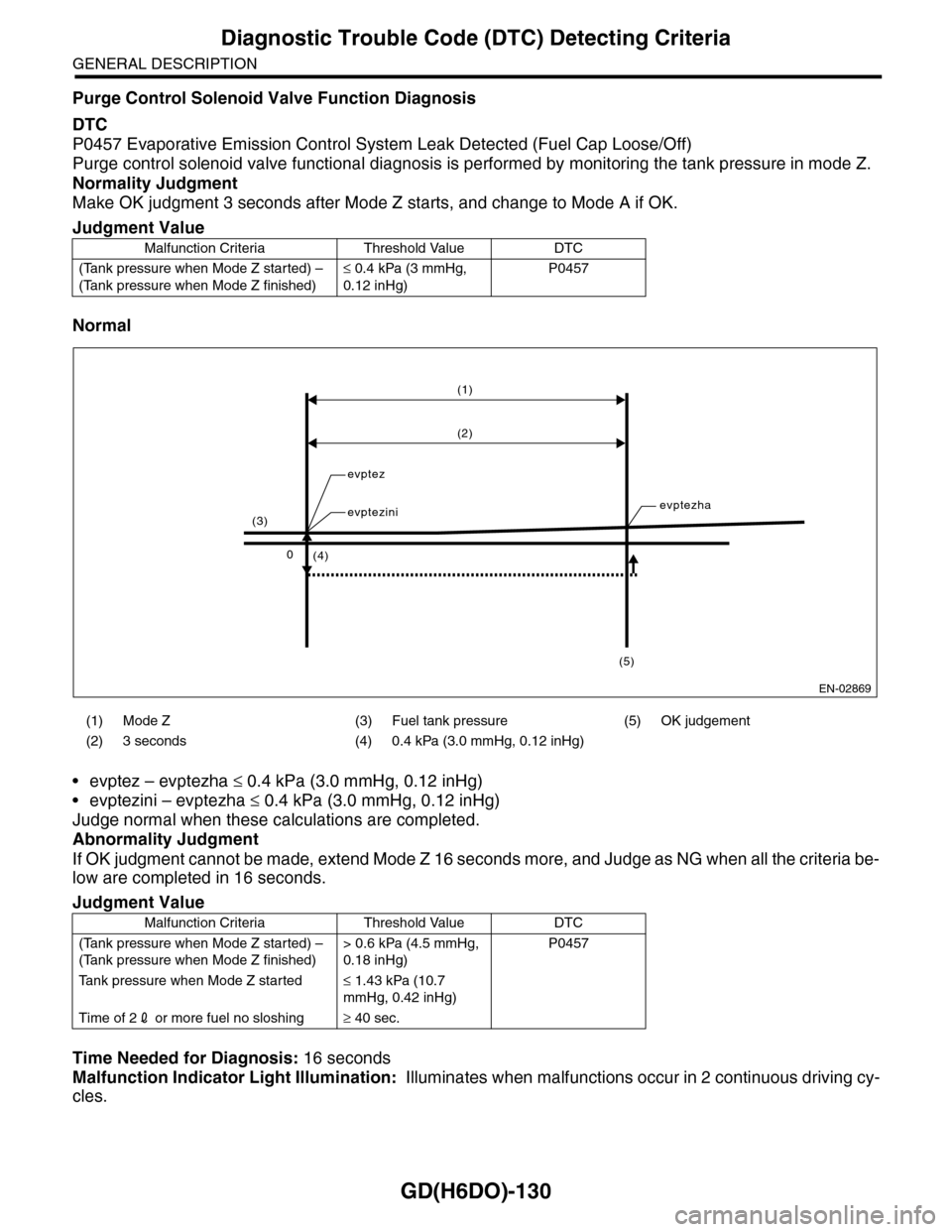
P0457 Evaporative Emission Control System Leak Detected (Fuel Cap Loose/Off)
Purge control solenoid valve functional diagnosis is performed by monitoring the tank pressure in mode Z.
Normality Judgment
Make OK judgment 3 seconds after Mode Z starts, and change to Mode A if OK.
Normal
•evptez – evptezha ≤ 0.4 kPa (3.0 mmHg, 0.12 inHg)
•evptezini – evptezha ≤ 0.4 kPa (3.0 mmHg, 0.12 inHg)
Judge normal when these calculations are completed.
Abnormality Judgment
If OK judgment cannot be made, extend Mode Z 16 seconds more, and Judge as NG when all the criteria be-
low are completed in 16 seconds.
Time Needed for Diagnosis: 16 seconds
Malfunction Indicator Light Illumination: Illuminates when malfunctions occur in 2 continuous driving cy-
cles.
Judgment Value
Malfunction Criteria Threshold Value DTC
(Tank pressure when Mode Z started) –
(Tank pressure when Mode Z finished)
≤ 0.4 kPa (3 mmHg,
0.12 inHg)
P0457
(1) Mode Z (3) Fuel tank pressure (5) OK judgement
(2) 3 seconds (4) 0.4 kPa (3.0 mmHg, 0.12 inHg)
Judgment Value
Malfunction Criteria Threshold Value DTC
(Tank pressure when Mode Z started) –
(Tank pressure when Mode Z finished)
> 0.6 kPa (4.5 mmHg,
0.18 inHg)
P0457
Ta n k p r e s s u r e w h e n M o d e Z s t a r t e d≤ 1.43 kPa (10.7
mmHg, 0.42 inHg)
Time of 22 or more fuel no sloshing≥ 40 sec.
EN-02869
(1)
(2)
(4)
evptez
evptezinievptezha
0
(3)
(5)
Page 1744 of 2453
GD(H6DO)-132
Diagnostic Trouble Code (DTC) Detecting Criteria
GENERAL DESCRIPTION
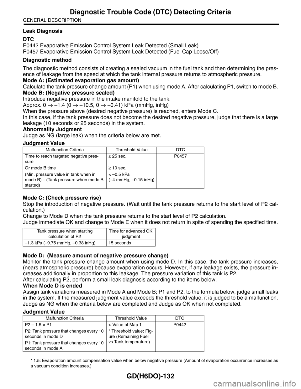
Leak Diagnosis
DTC
P0442 Evaporative Emission Control System Leak Detected (Small Leak)
P0457 Evaporative Emission Control System Leak Detected (Fuel Cap Loose/Off)
Diagnostic method
The diagnostic method consists of creating a sealed vacuum in the fuel tank and then determining the pres-
ence of leakage from the speed at which the tank internal pressure returns to atmospheric pressure.
Mode A: (Estimated evaporation gas amount)
Calculate the tank pressure change amount (P1) when using mode A. After calculating P1, switch to mode B.
Mode B: (Negative pressure sealed)
Introduce negative pressure in the intake manifold to the tank.
Approx. 0 → –1.4 (0 → –10.5, 0 → –0.41) kPa (mmHg, inHg)
When the pressure above (desired negative pressure) is reached, enters Mode C.
In this case, if the tank pressure does not become the desired negative pressure, judge that there is a large
leakage (10 seconds or 25 seconds) in the system.
Abnormality Judgment
Judge as NG (large leak) when the criteria below are met.
Mode C: (Check pressure rise)
Stop the introduction of negative pressure. (Wait until the tank pressure returns to the start level of P2 cal-
culation.)
Change to Mode D when the tank pressure returns to the start level of P2 calculation.
Judge immediate OK and change to Mode E when it does not return in spite of spending the specified time.
Mode D: (Measure amount of negative pressure change)
Monitor the tank pressure change amount when using mode D. In this case, the tank pressure increases,
(nears atmospheric pressure) because evaporation occurs. However, if any leakage exists, the pressure in-
creases additionally in proportion to this leakage. The pressure variation of this tank is P2.
After calculating P2, perform a small leak diagnosis according to the items below.
When Mode D is ended
Assign tank variations measured in Mode A and Mode B; P1 and P2, to the formula below, judge small leaks
in the system. If the measured judgment value exceeds the threshold value, it is judged to be a malfunction.
Judge as NG when the criteria below are completed and Judge as OK when not completed.
* 1.5: Evaporation amount compensation value when below negative pressure (Amount of evaporation occurrence increases as
a vacuum condition increases.)
Judgment Value
Malfunction Criteria Threshold Value DTC
Time to reach targeted negative pres-
sure
≥ 25 sec. P0457
Or mode B time≥ 10 sec.
(Min. pressure value in tank when in
mode B) – (Tank pressure when mode B
started)
< –0.5 kPa
(–4 mmHg, –0.15 inHg)
Ta n k p r e s s u r e w h e n s t a r t i n g
calculation of P2
Time for advanced OK
judgment
–1.3 kPa (–9.75 mmHg, –0.38 inHg) 15 seconds
Judgment Value
Malfunction Criteria Threshold Value DTC
P2 – 1.5 × P1 > Value of Map 1 P0442
P2: Tank pressure that changes every 10
seconds in mode D
* Threshold value: Fig-
ure (Remaining Fuel
vs Tank temperature)
P1: Tank pressure that changes every 10
seconds in mode A
Page 1758 of 2453
GD(H6DO)-146
Diagnostic Trouble Code (DTC) Detecting Criteria
GENERAL DESCRIPTION
CI: DTC P0456 EVAPORATIVE EMISSION CONTROL SYSTEM LEAK DETECT-
ED (VERY SMALL LEAK)
1. OUTLINE OF DIAGNOSIS
For the detection conditions, refer to DTC P0442 Evaporative system (Small leak).
tic Trouble Code (DTC) Detecting Criteria.>
CJ:DTC P0457 EVAPORATIVE EMISSION CONTROL SYSTEM LEAK DETECT-
ED (FUEL CAP LOOSE/OFF)
1. OUTLINE OF DIAGNOSIS
For the detection conditions, refer to DTC P0442 Evaporative system (Small leak).
tic Trouble Code (DTC) Detecting Criteria.>
Page 1951 of 2453
ME(H6DO)-85
Engine Trouble in General
MECHANICAL
2. Rough idle and engine
stall
Engine control system
Intake system Loosened or cracked intake duct A
Loosened or cracked PCV hose A
Loosened or cracked vacuum hose A
Defective intake manifold gasket B
Defective throttle body gasket B
Defective PCV valve C
Loosened oil filler cap B
Dirty air cleaner element C
Fuel line Defective fuel pump and relay C
Clogged fuel line C
Lack of or insufficient fuel B
Chain Defective timing C
Compression Incorrect valve clearance B
Loosened spark plug or defective gasket B
Loosened cylinder head bolt or defective gasket B
Improper valve sealing B
Defective valve stem C
Wor n or broken valve spr ing B
Wor n or stuck piston r ings, cylinder and piston B
Incorrect valve timing A
Improper engine oil (low viscosity) B
Tr o u b l e o f t a p p e t C
Tr o u b l e o f t a p p e t . I n c a s e n o i s e o c c u r s w i t h v a l v e m o v -
ing. Or the harness involved to oil switching solenoid
valve, variable valve lift diagnosis oil pressure switch
and variable valve lift has trouble in a past.
B
Lubrication system Incorrect oil pressure B
Defective rocker cover gasket C
Cooling system Over-heating C
Others Evaporative emission control system malfunction A
Stuck or damaged throttle valve B
Symptom Problem parts etc. Possible cause RANK