Page 1446 of 2453
EN(H6DO)(diag)-285
Diagnostic Procedure with Diagnostic Trouble Code (DTC)
ENGINE (DIAGNOSTICS)
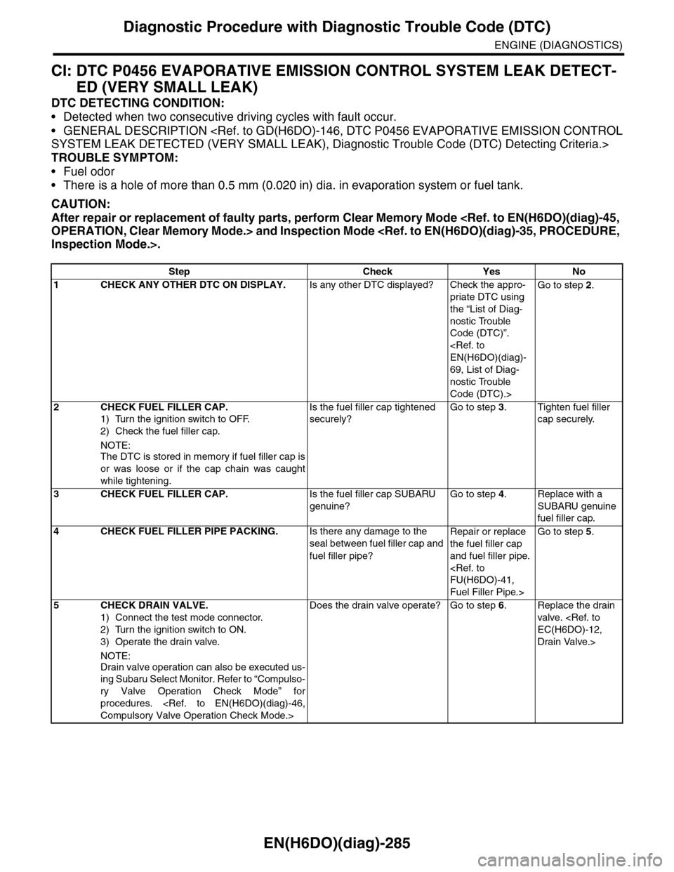
CI: DTC P0456 EVAPORATIVE EMISSION CONTROL SYSTEM LEAK DETECT-
ED (VERY SMALL LEAK)
DTC DETECTING CONDITION:
•Detected when two consecutive driving cycles with fault occur.
•GENERAL DESCRIPTION
SYSTEM LEAK DETECTED (VERY SMALL LEAK), Diagnostic Trouble Code (DTC) Detecting Criteria.>
TROUBLE SYMPTOM:
•Fuel odor
•There is a hole of more than 0.5 mm (0.020 in) dia. in evaporation system or fuel tank.
CAUTION:
After repair or replacement of faulty parts, perform Clear Memory Mode
OPERATION, Clear Memory Mode.> and Inspection Mode
Inspection Mode.>.
Step Check Yes No
1CHECK ANY OTHER DTC ON DISPLAY.Is any other DTC displayed? Check the appro-
priate DTC using
the “List of Diag-
nostic Trouble
Code (DTC)”.
EN(H6DO)(diag)-
69, List of Diag-
nostic Trouble
Code (DTC).>
Go to step 2.
2CHECK FUEL FILLER CAP.
1) Turn the ignition switch to OFF.
2) Check the fuel filler cap.
NOTE:
The DTC is stored in memory if fuel filler cap is
or was loose or if the cap chain was caught
while tightening.
Is the fuel filler cap tightened
securely?
Go to step 3.Tighten fuel filler
cap securely.
3CHECK FUEL FILLER CAP.Is the fuel filler cap SUBARU
genuine?
Go to step 4.Replace with a
SUBARU genuine
fuel filler cap.
4CHECK FUEL FILLER PIPE PACKING.Is there any damage to the
seal between fuel filler cap and
fuel filler pipe?
Repair or replace
the fuel filler cap
and fuel filler pipe.
FU(H6DO)-41,
Fuel Filler Pipe.>
Go to step 5.
5CHECK DRAIN VALVE.
1) Connect the test mode connector.
2) Turn the ignition switch to ON.
3) Operate the drain valve.
NOTE:
Drain valve operation can also be executed us-
ing Subaru Select Monitor. Refer to “Compulso-
ry Valve Operation Check Mode” for
procedures.
Compulsory Valve Operation Check Mode.>
Does the drain valve operate? Go to step 6.Replace the drain
valve.
EC(H6DO)-12,
Drain Valve.>
Page 1448 of 2453
EN(H6DO)(diag)-287
Diagnostic Procedure with Diagnostic Trouble Code (DTC)
ENGINE (DIAGNOSTICS)
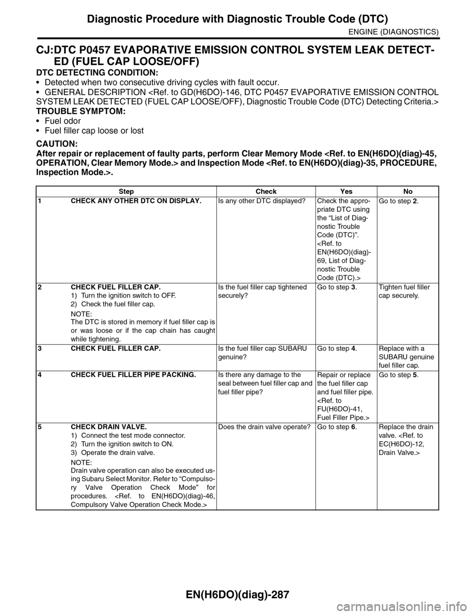
CJ:DTC P0457 EVAPORATIVE EMISSION CONTROL SYSTEM LEAK DETECT-
ED (FUEL CAP LOOSE/OFF)
DTC DETECTING CONDITION:
•Detected when two consecutive driving cycles with fault occur.
•GENERAL DESCRIPTION
SYSTEM LEAK DETECTED (FUEL CAP LOOSE/OFF), Diagnostic Trouble Code (DTC) Detecting Criteria.>
TROUBLE SYMPTOM:
•Fuel odor
•Fuel filler cap loose or lost
CAUTION:
After repair or replacement of faulty parts, perform Clear Memory Mode
OPERATION, Clear Memory Mode.> and Inspection Mode
Inspection Mode.>.
Step Check Yes No
1CHECK ANY OTHER DTC ON DISPLAY.Is any other DTC displayed? Check the appro-
priate DTC using
the “List of Diag-
nostic Trouble
Code (DTC)”.
EN(H6DO)(diag)-
69, List of Diag-
nostic Trouble
Code (DTC).>
Go to step 2.
2CHECK FUEL FILLER CAP.
1) Turn the ignition switch to OFF.
2) Check the fuel filler cap.
NOTE:
The DTC is stored in memory if fuel filler cap is
or was loose or if the cap chain has caught
while tightening.
Is the fuel filler cap tightened
securely?
Go to step 3.Tighten fuel filler
cap securely.
3CHECK FUEL FILLER CAP.Is the fuel filler cap SUBARU
genuine?
Go to step 4.Replace with a
SUBARU genuine
fuel filler cap.
4CHECK FUEL FILLER PIPE PACKING.Is there any damage to the
seal between fuel filler cap and
fuel filler pipe?
Repair or replace
the fuel filler cap
and fuel filler pipe.
FU(H6DO)-41,
Fuel Filler Pipe.>
Go to step 5.
5CHECK DRAIN VALVE.
1) Connect the test mode connector.
2) Turn the ignition switch to ON.
3) Operate the drain valve.
NOTE:
Drain valve operation can also be executed us-
ing Subaru Select Monitor. Refer to “Compulso-
ry Valve Operation Check Mode” for
procedures.
Compulsory Valve Operation Check Mode.>
Does the drain valve operate? Go to step 6.Replace the drain
valve.
EC(H6DO)-12,
Drain Valve.>
Page 1563 of 2453
FU(H6DO)-2
General Description
FUEL INJECTION (FUEL SYSTEMS)
1. General Description
A: SPECIFICATION
Fuel tankCapacity 64 2 (16.9 US gal, 14.1 Imp gal)
Location Rear floor bottom
Fuel pump
Ty p e I m p e l l e r
Shutoff discharge pressure550 — 850 kPa (5.61 — 8.67 kg/cm2, 79.8 — 123.3 psi)
Discharge rate155 2 (41 US gal, 34.1 Imp gal)/h or more
[12 V at 300 kPa (3.06 kg/cm2, 43.5 psi)]
Fuel filterIn-tank type
Page 1570 of 2453
FU(H6DO)-9
General Description
FUEL INJECTION (FUEL SYSTEMS)
6. FUEL LINE
(1) Clamp (8) Fuel pipe ASSY (15) Ring
(2) Evaporation hose A (9) Grommet (16) Fuel filler cap
(3) Fuel delivery hose A (10) Drain valve (17) Fuel tank pressure sensor
(4) Fuel pipe ASSY (11) Canister
(5) Evaporation hose B (12) ClampTightening torque: N·m (kgf-m, ft-lb)
(6) Fuel delivery hose B (13) Fuel filler pipeT1: 7.5 (0.76, 5.5)
(7) Clamp (14) Packing
C
C
A
AB
B
(15)
(13)(17)
(16)
(14)
T1
T2
(5)
(6)
(4)
(7)(7)
(8)
(9)
(11)
(12)
(12)
(10)
(2)
(3)(1)
FU-02678
Page 1571 of 2453
FU(H6DO)-10
General Description
FUEL INJECTION (FUEL SYSTEMS)
C: CAUTION
•Wear work clothing, including a cap, protective goggles and protective shoes during operation.
•Remove contamination including dirt and corrosion before removal, installation or disassembly.
•Keep the disassembled parts in order and protect them from dust and dirt.
•Before removal, installation or disassembly, be sure to clarify the failure. Avoid unnecessary removal, in-
stallation, disassembly and replacement.
•Be careful not to burn yourself, because each part on the vehicle is hot after running.
•Be sure to tighten fasteners including bolts and nuts to the specified torque.
•Place shop jacks or rigid racks at the specified points.
•Before disconnecting connectors of sensors or units, be sure to disconnect the ground cable from the bat-
tery.
•Place “NO FIRE” signs near the working area.
•Be careful not to spill fuel on the floor.
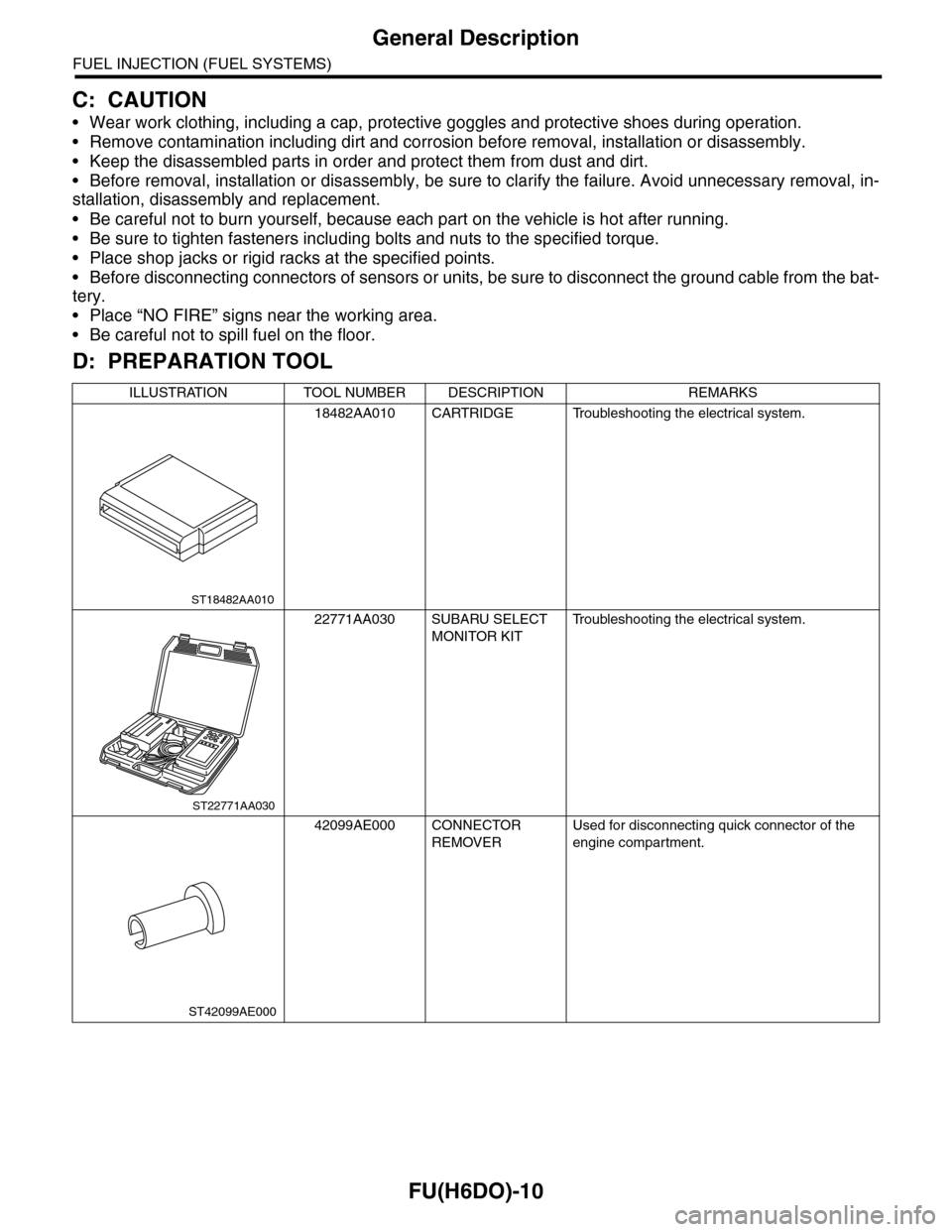
D: PREPARATION TOOL
ILLUSTRATION TOOL NUMBER DESCRIPTION REMARKS
18482AA010 CARTRIDGE Troubleshooting the electrical system.
22771AA030 SUBARU SELECT
MONITOR KIT
Tr o u b l e s h o o t i n g t h e e l e c t r i c a l s y s t e m .
42099AE000 CONNECTOR
REMOVER
Used for disconnecting quick connector of the
engine compartment.
ST18482AA010
ST22771AA030
ST42099AE000
Page 1573 of 2453
FU(H6DO)-12
Intake Manifold
FUEL INJECTION (FUEL SYSTEMS)
3. Intake Manifold
A: REMOVAL
1) Remove the collector cover.
2) Release the fuel pressure.
37, RELEASING OF FUEL PRESSURE, PROCE-
DURE, Fuel.>
3) Disconnect the ground cable from battery.
4) Open the fuel filler flap lid, and remove the fuel
filler cap.
5) Remove the air cleaner case and air intake
chamber.
Cleaner Case.>
Air Intake Chamber.>
6) Remove the generator.
REMOVAL, Generator.>
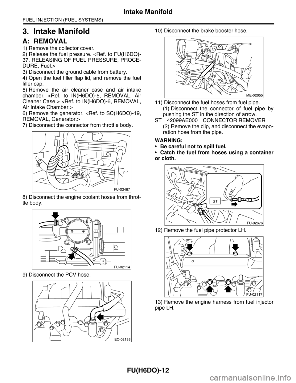
7) Disconnect the connector from throttle body.
8) Disconnect the engine coolant hoses from throt-
tle body.
9) Disconnect the PCV hose.
10) Disconnect the brake booster hose.
11) Disconnect the fuel hoses from fuel pipe.
(1) Disconnect the connector of fuel pipe by
pushing the ST in the direction of arrow.
ST 42099AE000 CONNECTOR REMOVER
(2) Remove the clip, and disconnect the evapo-
ration hose from the pipe.
WARNING:
•Be careful not to spill fuel.
•Catch the fuel from hoses using a container
or cloth.
12) Remove the fuel pipe protector LH.
13) Remove the engine harness from fuel injector
pipe LH.
FU-02487
FU-02114
EC-02133
ME-02655
FU-02117
Page 1585 of 2453
FU(H6DO)-24
Fuel Injector
FUEL INJECTION (FUEL SYSTEMS)
11.Fuel Injector
A: REMOVAL
1. RH SIDE
1) Remove the collector cover.
2) Release the fuel pressure.
37, RELEASING OF FUEL PRESSURE, PROCE-
DURE, Fuel.>
3) Disconnect the ground cable from battery.
4) Open the fuel filler flap lid, and remove the fuel
filler cap.
5) Remove the air cleaner case.
IN(H6DO)-5, REMOVAL, Air Cleaner Case.>
6) Remove the fuel pipe protector RH.
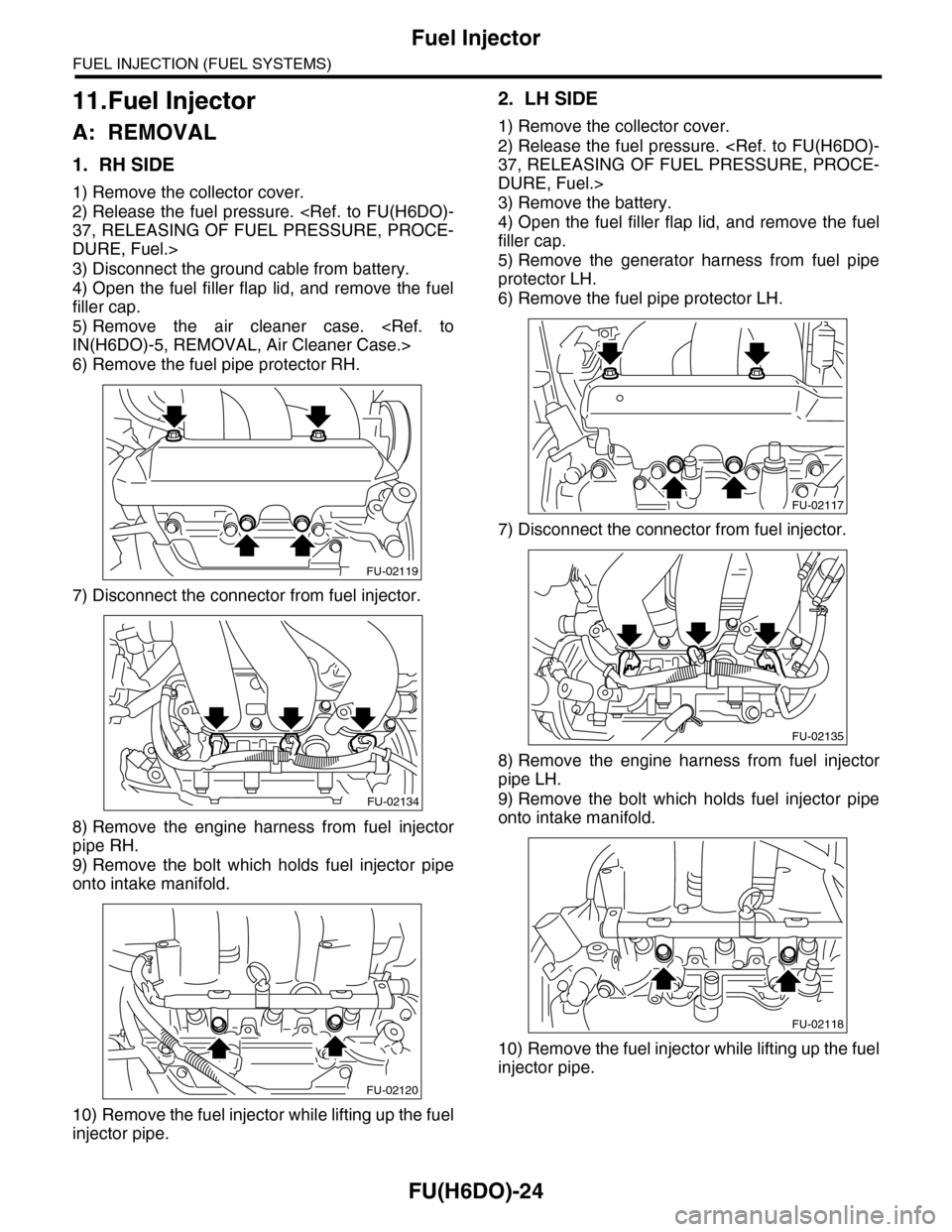
7) Disconnect the connector from fuel injector.
8) Remove the engine harness from fuel injector
pipe RH.
9) Remove the bolt which holds fuel injector pipe
onto intake manifold.
10) Remove the fuel injector while lifting up the fuel
injector pipe.
2. LH SIDE
1) Remove the collector cover.
2) Release the fuel pressure.
37, RELEASING OF FUEL PRESSURE, PROCE-
DURE, Fuel.>
3) Remove the battery.
4) Open the fuel filler flap lid, and remove the fuel
filler cap.
5) Remove the generator harness from fuel pipe
protector LH.
6) Remove the fuel pipe protector LH.
7) Disconnect the connector from fuel injector.
8) Remove the engine harness from fuel injector
pipe LH.
9) Remove the bolt which holds fuel injector pipe
onto intake manifold.
10) Remove the fuel injector while lifting up the fuel
injector pipe.
FU-02119
FU-02134
FU-02120
FU-02117
FU-02135
FU-02118
Page 1598 of 2453
FU(H6DO)-37
Fuel
FUEL INJECTION (FUEL SYSTEMS)
21.Fuel
A: PROCEDURE
1. RELEASING OF FUEL PRESSURE
WARNING:
•Place “NO FIRE” signs near the working area.
•Be careful not to spill fuel on the floor.
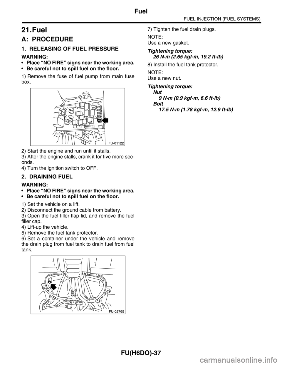
1) Remove the fuse of fuel pump from main fuse
box.
2) Start the engine and run until it stalls.
3) After the engine stalls, crank it for five more sec-
onds.
4) Turn the ignition switch to OFF.
2. DRAINING FUEL
WARNING:
•Place “NO FIRE” signs near the working area.
•Be careful not to spill fuel on the floor.
1) Set the vehicle on a lift.
2) Disconnect the ground cable from battery.
3) Open the fuel filler flap lid, and remove the fuel
filler cap.
4) Lift-up the vehicle.
5) Remove the fuel tank protector.
6) Set a container under the vehicle and remove
the drain plug from fuel tank to drain fuel from fuel
tank.
7) Tighten the fuel drain plugs.
NOTE:
Use a new gasket.
Tightening torque:
26 N·m (2.65 kgf-m, 19.2 ft-lb)
8) Install the fuel tank protector.
NOTE:
Use a new nut.
Tightening torque:
Nut
9 N·m (0.9 kgf-m, 6.6 ft-lb)
Bolt
17.5 N·m (1.78 kgf-m, 12.9 ft-lb)
FU-01122
FU-02765