Page 1554 of 2453
EN(H6DO)(diag)-393
General Diagnostic Table
ENGINE (DIAGNOSTICS)
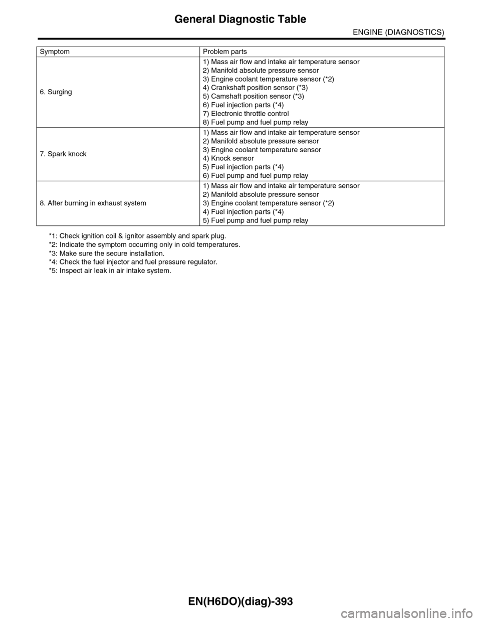
*1: Check ignition coil & ignitor assembly and spark plug.
*2: Indicate the symptom occurring only in cold temperatures.
*3: Make sure the secure installation.
*4: Check the fuel injector and fuel pressure regulator.
*5: Inspect air leak in air intake system.
6. Surging
1) Mass air flow and intake air temperature sensor
2) Manifold absolute pressure sensor
3) Engine coolant temperature sensor (*2)
4) Crankshaft position sensor (*3)
5) Camshaft position sensor (*3)
6) Fuel injection parts (*4)
7) Electronic throttle control
8) Fuel pump and fuel pump relay
7. Spark knock
1) Mass air flow and intake air temperature sensor
2) Manifold absolute pressure sensor
3) Engine coolant temperature sensor
4) Knock sensor
5) Fuel injection parts (*4)
6) Fuel pump and fuel pump relay
8. After burning in exhaust system
1) Mass air flow and intake air temperature sensor
2) Manifold absolute pressure sensor
3) Engine coolant temperature sensor (*2)
4) Fuel injection parts (*4)
5) Fuel pump and fuel pump relay
Symptom Problem parts
Page 1567 of 2453
FU(H6DO)-6
General Description
FUEL INJECTION (FUEL SYSTEMS)
4. CRANKSHAFT POSITION, CAMSHAFT POSITION AND KNOCK SENSORS
(1) Crankshaft position sensor (6) Variable valve lift diagnosis oil
pressure switch RH
Tightening torque: N·m (kgf-m, ft-lb)
(2) Knock sensor RHT1: 6.4 (0.65, 4.7)
(3) Knock sensor LH (7) Variable valve lift diagnosis oil
pressure switch LH
T2: 17 (1.7, 12.5)
(4) Camshaft position sensor RHT3: 18 (1.8, 13.3)
(5) Camshaft position sensor LH (8) Oil temperature sensorT4: 25 (2.5, 18)
FU-02110
(6)
(4)
T2
T1
(3)
T4
(1)
(8)
T1
T3
(5)
T1
(2)
T4
(7)
T2
Page 1581 of 2453
FU(H6DO)-20
Knock Sensor
FUEL INJECTION (FUEL SYSTEMS)
7. Knock Sensor
A: REMOVAL
1) Remove the collector cover.
2) Disconnect the ground cable from battery.
3) Remove the intake manifold.
fold.>
4) Disconnect the knock sensor connector.
5) Remove the knock sensor from cylinder block.
B: INSTALLATION
1) Install the knock sensor to cylinder block.
Tightening torque:
25 N·m (2.5 kgf-m, 18 ft-lb)
NOTE:
For the knock sensor installation angle, refer to the
figure below.
2) Connect the knock sensor connector.
3) Install the intake manifold.
13, INSTALLATION, Intake Manifold.>
4) Connect the battery ground cable to the battery.
5) Install the collector cover.
(A) Front side of vehicle
FU-00577
45˚30˚10˚
(A)FU-00578
Page 1617 of 2453
GD(H6DO)-5
List of Diagnostic Trouble Code (DTC)
GENERAL DESCRIPTION
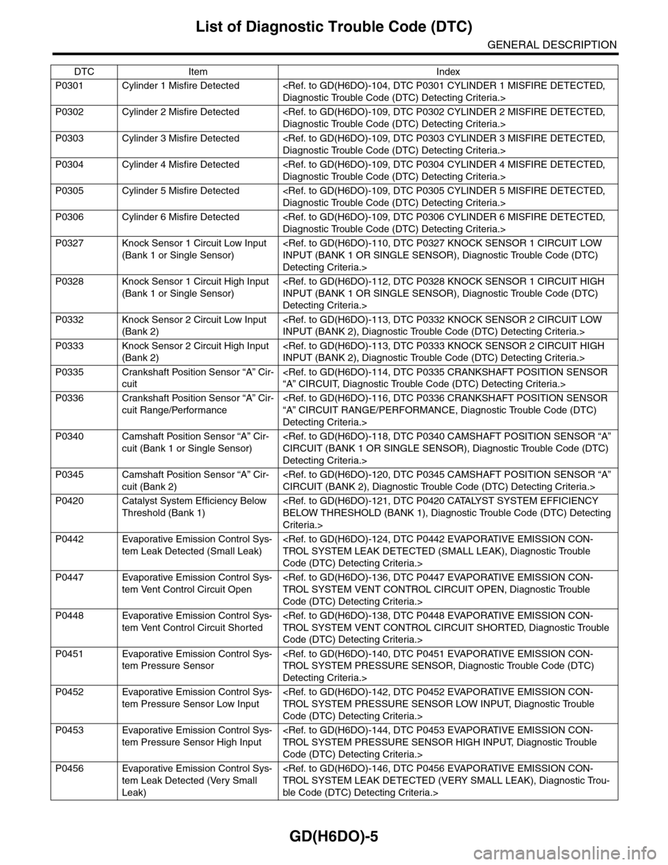
P0301 Cylinder 1 Misfire Detected
Diagnostic Trouble Code (DTC) Detecting Criteria.>
P0302 Cylinder 2 Misfire Detected
Diagnostic Trouble Code (DTC) Detecting Criteria.>
P0303 Cylinder 3 Misfire Detected
Diagnostic Trouble Code (DTC) Detecting Criteria.>
P0304 Cylinder 4 Misfire Detected
Diagnostic Trouble Code (DTC) Detecting Criteria.>
P0305 Cylinder 5 Misfire Detected
Diagnostic Trouble Code (DTC) Detecting Criteria.>
P0306 Cylinder 6 Misfire Detected
Diagnostic Trouble Code (DTC) Detecting Criteria.>
P0327 Knock Sensor 1 Circuit Low Input
(Bank 1 or Single Sensor)
INPUT (BANK 1 OR SINGLE SENSOR), Diagnostic Trouble Code (DTC)
Detecting Criteria.>
P0328 Knock Sensor 1 Circuit High Input
(Bank 1 or Single Sensor)
INPUT (BANK 1 OR SINGLE SENSOR), Diagnostic Trouble Code (DTC)
Detecting Criteria.>
P0332 Knock Sensor 2 Circuit Low Input
(Bank 2)
INPUT (BANK 2), Diagnostic Trouble Code (DTC) Detecting Criteria.>
P0333 Knock Sensor 2 Circuit High Input
(Bank 2)
INPUT (BANK 2), Diagnostic Trouble Code (DTC) Detecting Criteria.>
P0335 Crankshaft Position Sensor “A” Cir-
cuit
“A” CIRCUIT, Diagnostic Trouble Code (DTC) Detecting Criteria.>
P0336 Crankshaft Position Sensor “A” Cir-
cuit Range/Performance
“A” CIRCUIT RANGE/PERFORMANCE, Diagnostic Trouble Code (DTC)
Detecting Criteria.>
P0340 Camshaft Position Sensor “A” Cir-
cuit (Bank 1 or Single Sensor)
CIRCUIT (BANK 1 OR SINGLE SENSOR), Diagnostic Trouble Code (DTC)
Detecting Criteria.>
P0345 Camshaft Position Sensor “A” Cir-
cuit (Bank 2)
CIRCUIT (BANK 2), Diagnostic Trouble Code (DTC) Detecting Criteria.>
P0420 Catalyst System Efficiency Below
Threshold (Bank 1)
BELOW THRESHOLD (BANK 1), Diagnostic Trouble Code (DTC) Detecting
Criteria.>
P0442 Evaporative Emission Control Sys-
tem Leak Detected (Small Leak)
TROL SYSTEM LEAK DETECTED (SMALL LEAK), Diagnostic Trouble
Code (DTC) Detecting Criteria.>
P0447 Evaporative Emission Control Sys-
tem Vent Control Circuit Open
TROL SYSTEM VENT CONTROL CIRCUIT OPEN, Diagnostic Trouble
Code (DTC) Detecting Criteria.>
P0448 Evaporative Emission Control Sys-
tem Vent Control Circuit Shorted
TROL SYSTEM VENT CONTROL CIRCUIT SHORTED, Diagnostic Trouble
Code (DTC) Detecting Criteria.>
P0451 Evaporative Emission Control Sys-
tem Pressure Sensor
TROL SYSTEM PRESSURE SENSOR, Diagnostic Trouble Code (DTC)
Detecting Criteria.>
P0452 Evaporative Emission Control Sys-
tem Pressure Sensor Low Input
TROL SYSTEM PRESSURE SENSOR LOW INPUT, Diagnostic Trouble
Code (DTC) Detecting Criteria.>
P0453 Evaporative Emission Control Sys-
tem Pressure Sensor High Input
TROL SYSTEM PRESSURE SENSOR HIGH INPUT, Diagnostic Trouble
Code (DTC) Detecting Criteria.>
P0456 Evaporative Emission Control Sys-
tem Leak Detected (Very Small
Leak)
TROL SYSTEM LEAK DETECTED (VERY SMALL LEAK), Diagnostic Trou-
ble Code (DTC) Detecting Criteria.>
DTC Item Index
Page 1722 of 2453
GD(H6DO)-110
Diagnostic Trouble Code (DTC) Detecting Criteria
GENERAL DESCRIPTION
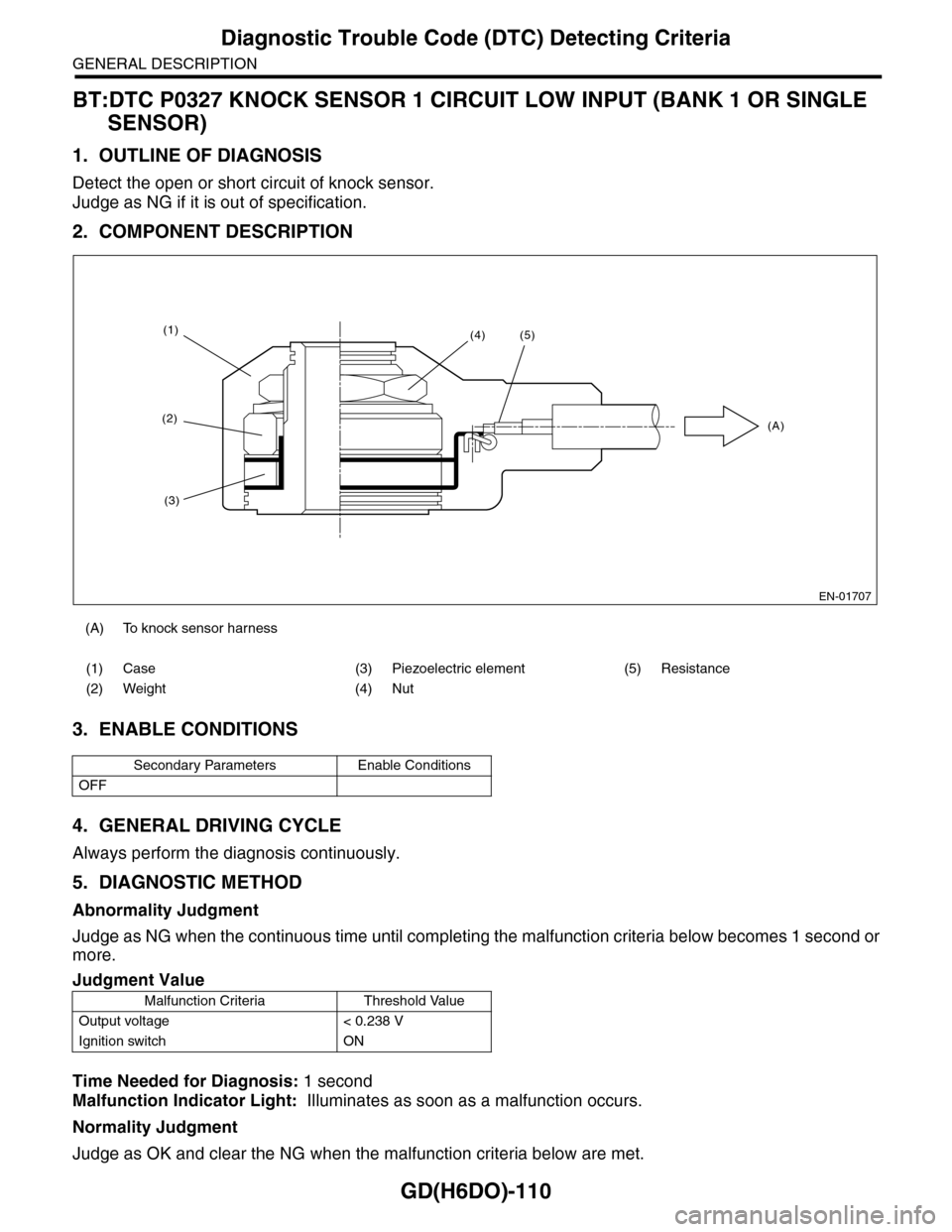
BT:DTC P0327 KNOCK SENSOR 1 CIRCUIT LOW INPUT (BANK 1 OR SINGLE
SENSOR)
1. OUTLINE OF DIAGNOSIS
Detect the open or short circuit of knock sensor.
Judge as NG if it is out of specification.
2. COMPONENT DESCRIPTION
3. ENABLE CONDITIONS
4. GENERAL DRIVING CYCLE
Always perform the diagnosis continuously.
5. DIAGNOSTIC METHOD
Abnormality Judgment
Judge as NG when the continuous time until completing the malfunction criteria below becomes 1 second or
more.
Time Needed for Diagnosis: 1 second
Malfunction Indicator Light: Illuminates as soon as a malfunction occurs.
Normality Judgment
Judge as OK and clear the NG when the malfunction criteria below are met.
(A) To knock sensor harness
(1) Case (3) Piezoelectric element (5) Resistance
(2) Weight (4) Nut
Secondary Parameters Enable Conditions
OFF
Judgment Value
Malfunction Criteria Threshold Value
Output voltage < 0.238 V
Ignition switch ON
EN-01707
(1)
(2)
(3)
(4)(5)
(A)
Page 1724 of 2453
GD(H6DO)-112
Diagnostic Trouble Code (DTC) Detecting Criteria
GENERAL DESCRIPTION
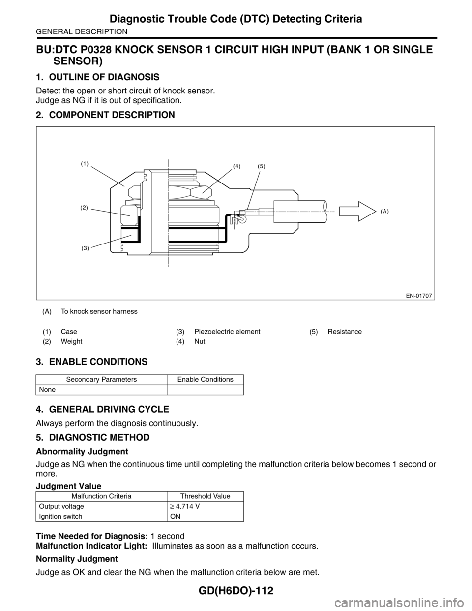
BU:DTC P0328 KNOCK SENSOR 1 CIRCUIT HIGH INPUT (BANK 1 OR SINGLE
SENSOR)
1. OUTLINE OF DIAGNOSIS
Detect the open or short circuit of knock sensor.
Judge as NG if it is out of specification.
2. COMPONENT DESCRIPTION
3. ENABLE CONDITIONS
4. GENERAL DRIVING CYCLE
Always perform the diagnosis continuously.
5. DIAGNOSTIC METHOD
Abnormality Judgment
Judge as NG when the continuous time until completing the malfunction criteria below becomes 1 second or
more.
Time Needed for Diagnosis: 1 second
Malfunction Indicator Light: Illuminates as soon as a malfunction occurs.
Normality Judgment
Judge as OK and clear the NG when the malfunction criteria below are met.
(A) To knock sensor harness
(1) Case (3) Piezoelectric element (5) Resistance
(2) Weight (4) Nut
Secondary Parameters Enable Conditions
None
Judgment Value
Malfunction Criteria Threshold Value
Output voltage≥ 4.714 V
Ignition switch ON
EN-01707
(1)
(2)
(3)
(4)(5)
(A)
Page 1725 of 2453
GD(H6DO)-113
Diagnostic Trouble Code (DTC) Detecting Criteria
GENERAL DESCRIPTION
6. DTC CLEAR CONDITION
•When the OK idling cycle is completed 40 times in a row
•When “Clear Memory” is performed
7. MALFUNCTION INDICATOR LIGHT CLEAR CONDITIONS
•When the OK driving cycle is completed 3 times in a row
•When “Clear Memory” is performed
8. FAIL SAFE
Knocking compensation
When normal: Learning ignition advance angle value = knock F/B advance angle + entire learning advance
angle value + portional learning advance angle value
Failure: Learning ignition advance angle value = –5.0°CA
Knock F/B advancing angle = 0°CA
Whole learning prohibited
Portional learning prohibited
9. ECM OPERATION AT DTC SETTING
Memorize the freeze frame data. (For test mode $02)
BV:DTC P0332 KNOCK SENSOR 2 CIRCUIT LOW INPUT (BANK 2)
1. OUTLINE OF DIAGNOSIS
NOTE:
For the diagnostic procedure, refer to DTC P0327.
1 CIRCUIT LOW INPUT (BANK 1 OR SINGLE SENSOR), Diagnostic Trouble Code (DTC) Detecting Crite-
ria.>
BW:DTC P0333 KNOCK SENSOR 2 CIRCUIT HIGH INPUT (BANK 2)
1. OUTLINE OF DIAGNOSIS
NOTE:
For the diagnostic procedure, refer to DTC P0328.
1 CIRCUIT HIGH INPUT (BANK 1 OR SINGLE SENSOR), Diagnostic Trouble Code (DTC) Detecting Crite-
ria.>
Judgment Value
Malfunction Criteria Threshold Value
Output voltage < 4.714 V
Ignition switch ON
Page 1906 of 2453
ME(H6DO)-40
Preparation for Overhaul
MECHANICAL
12.Preparation for Overhaul
A: REMOVAL
1) Remove the engine assembly from the body.
sembly.>
2) Set the engine on ST.
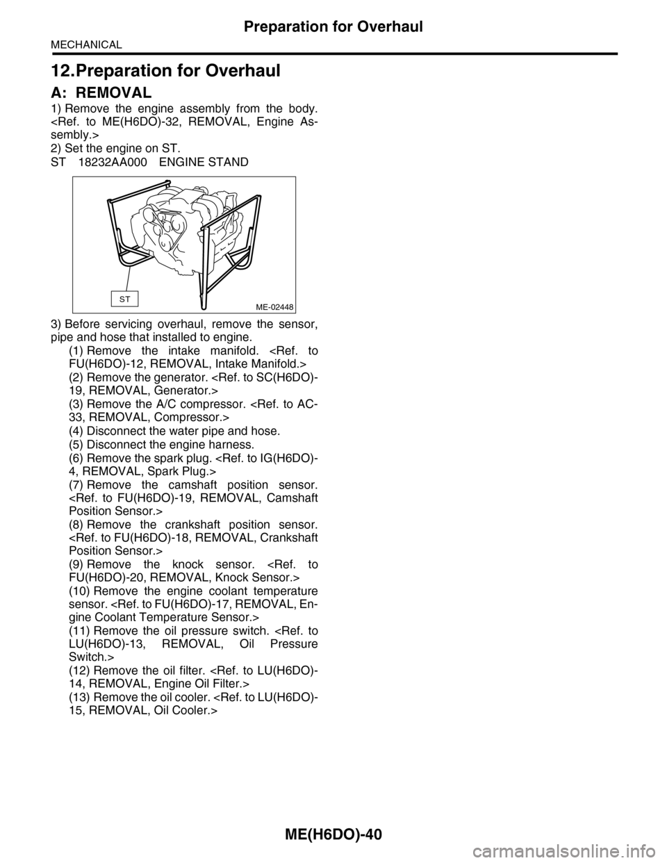
ST 18232AA000 ENGINE STAND
3) Before servicing overhaul, remove the sensor,
pipe and hose that installed to engine.
(1) Remove the intake manifold.
FU(H6DO)-12, REMOVAL, Intake Manifold.>
(2) Remove the generator.
19, REMOVAL, Generator.>
(3) Remove the A/C compressor.
33, REMOVAL, Compressor.>
(4) Disconnect the water pipe and hose.
(5) Disconnect the engine harness.
(6) Remove the spark plug.
4, REMOVAL, Spark Plug.>
(7) Remove the camshaft position sensor.
Position Sensor.>
(8) Remove the crankshaft position sensor.
Position Sensor.>
(9) Remove the knock sensor.
FU(H6DO)-20, REMOVAL, Knock Sensor.>
(10) Remove the engine coolant temperature
sensor.
gine Coolant Temperature Sensor.>
(11) Remove the oil pressure switch.
LU(H6DO)-13, REMOVAL, Oil Pressure
Switch.>
(12) Remove the oil filter.
14, REMOVAL, Engine Oil Filter.>
(13) Remove the oil cooler.
15, REMOVAL, Oil Cooler.>
STME-02448