2009 SUBARU TRIBECA B135 - 30
[x] Cancel search: B135 - 30Page 783 of 2453

BVC(diag)-28
Diagnostic Procedure with Diagnostic Trouble Code (DTC)
BRAKE VACUUM CONTROL (BVC) (DIAGNOSTICS)
F: DTC 23 PUMP CONTINUOUS OPERATION
DTC DETECTING CONDITION:
Brake vacuum pump malfunction
TROUBLE SYMPTOM:
Break vacuum pump operates continuously.
WIRING DIAGRAM:
BR-00528
2
1
B25B
B422
1234
B432
2
1
4
36
5
8
7
B432
SBF HOLDER
3
7
14
21
53
43
VC2
VC3
B422
B422
VC3
RELAY BOX(VACUUMPUMP RELAY)
B417
VAC U U MPUMP
26
41
B47
MAINRELAY
B411
VAC U U M S E N S O RECM
A: B134B: B135C: B136
C23B30B22A27C8312
JOINT CONNECTOR
B424
**
B417B411
213
B: C:B135
5672134
29
101112131415252416
30
98171819202821222332312627333435
B136
16101112131415252430
9871718192028212223293231
123456
2726333435
VC2
A:B134
85610 11 12 13 14 157213416
3019 20 2228 29
91718252123 24323126 2733 34
B424
34561278
(BROWN)
21
5436
B47
* : TERMINAL NO. OPTIONAL ARRANGEMENT
21
SBF-7BATTERY
30A
3412
5
8967
10131211
14
Page 784 of 2453

BVC(diag)-29
Diagnostic Procedure with Diagnostic Trouble Code (DTC)
BRAKE VACUUM CONTROL (BVC) (DIAGNOSTICS)
Step Check Yes No
1CHECK BRAKE VACUUM HOSE.
1) Turn the ignition switch to OFF.
2) Check that status of the brake vacuum
hose connection.
Is the brake vacuum hose con-
nected firmly?
Go to step 2.Connect the brake
vacuum hose.
2CHECK BRAKE VACUUM HOSE.
1) Turn the ignition switch to ON and start
engine.
2) Check for leakage from the brake vacuum
hose.
Is there a leak from the brake
vacuum hose?
Replace the brake
vacuum hose.
Go to step 3.
3CHECK BRAKE VACUUM PUMP RELAY.
1) Turn the ignition switch to OFF.
2) Remove the brake vacuum pump relay from
the relay box.
3) Connect the battery to terminals No. 1 and
No. 3 of the brake vacuum pump relay.
4) Measure the resistance between the brake
vacuum pump relay terminals.
Te r m i n a l s
No. 4 — No. 5:
Is the resistance less than 1
Ω?
Go to step 4.Replace the brake
vacuum pump
relay.
4CHECK BRAKE VACUUM PUMP RELAY
POWER SUPPLY.
1) Turn the ignition switch to ON.
2) Measure the voltage between brake vac-
uum pump relay connector and chassis
ground.
Connector & terminal
(VC2) No. 1 (+) — Chassis ground (–):
(VC2) No. 4 (+) — Chassis ground (–):
Is the voltage more than 10 V? Go to step 5.Repair the open or
ground short cir-
cuit of power sup-
ply circuit.
5CHECK HARNESS BETWEEN ECM AND
BRAKE VACUUM PUMP RELAY CONNEC-
TOR.
1) Turn the ignition switch to OFF.
2) Disconnect the connector of ECM.
3) Measure the resistance of the harness
between ECM and the brake vacuum pump
relay connector.
Connector & terminal
(B136) No. 8 — (VC2) No. 3:
(B135) No. 25 — (VC2) No. 5:
Is the resistance less than 1
Ω?
Go to step 6.Repair the open
circuit of harness
between ECM and
the brake vacuum
pump relay con-
nector.
6CHECK HARNESS BETWEEN THE BRAKE
VACUUM PUMP AND BRAKE VACUUM
PUMP RELAY CONNECTOR.
1) Turn the ignition switch to OFF.
2) Disconnect the brake vacuum pump con-
nector.
3) Measure the resistance of the harness
between the brake vacuum pump and brake
vacuum pump relay connector.
Connector & terminal
(VC2) No. 5 — (B417) No. 1:
Is the resistance less than 1
Ω?
Go to step 7.Repair the open
circuit of the har-
ness between the
brake vacuum
pump and the
brake vacuum
pump relay con-
nector.
7CHECK ECM.
1) Connect the brake vacuum pump relay.
2) Connect the connectors to the brake vac-
uum pump and ECM.
3) Turn the ignition switch to ON.
4) Measure the voltage between ECM and
chassis ground.
Connector & terminal
(B136) No. 8 — Chassis ground (–):
Is the voltage more than 10 V? Replace the ECM.
Engine Control
Module (ECM).>
Te m p o r a r y p o o r
contact occurs.
Page 1177 of 2453
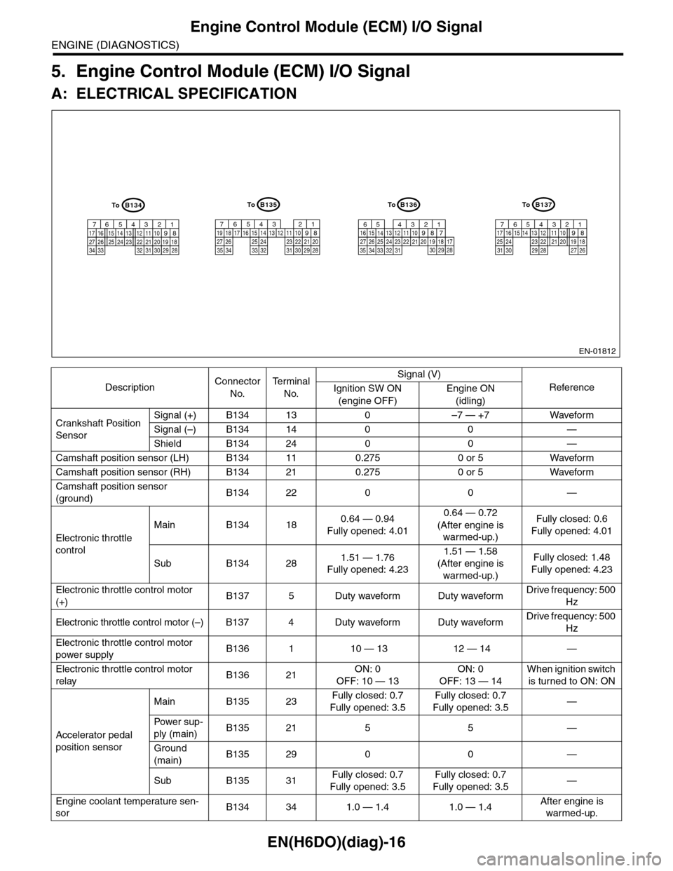
EN(H6DO)(diag)-16
Engine Control Module (ECM) I/O Signal
ENGINE (DIAGNOSTICS)
5. Engine Control Module (ECM) I/O Signal
A: ELECTRICAL SPECIFICATION
DescriptionConnector
No.
Te r m i n a l
No.
Signal (V)
ReferenceIgnition SW ON
(engine OFF)
Engine ON
(idling)
Crankshaft Position
Sensor
Signal (+) B134 13 0 –7 — +7 Waveform
Signal (–) B134 14 0 0 —
Shield B134 24 0 0 —
Camshaft position sensor (LH) B134 11 0.275 0 or 5 Waveform
Camshaft position sensor (RH) B134 21 0.275 0 or 5 Waveform
Camshaft position sensor
(ground)B134 22 0 0 —
Electronic throttle
control
Main B134 180.64 — 0.94
Fully opened: 4.01
0.64 — 0.72
(After engine is
warmed-up.)
Fully closed: 0.6
Fully opened: 4.01
Sub B134 281.51 — 1.76
Fully opened: 4.23
1.51 — 1.58
(After engine is
warmed-up.)
Fully closed: 1.48
Fully opened: 4.23
Electronic throttle control motor
(+)B137 5 Duty waveform Duty waveformDrive frequency: 500
Hz
Electronic throttle control motor (–) B137 4 Duty waveform Duty waveformDrive frequency: 500
Hz
Electronic throttle control motor
power supplyB136 1 10 — 13 12 — 14 —
Electronic throttle control motor
relayB136 21ON: 0
OFF: 10 — 13
ON: 0
OFF: 13 — 14
When ignition switch
is turned to ON: ON
Accelerator pedal
position sensor
Main B135 23Fully closed: 0.7
Fully opened: 3.5
Fully closed: 0.7
Fully opened: 3.5—
Powe r s up -
ply (main)B135 21 5 5 —
Ground
(main)B135 29 0 0 —
Sub B135 31Fully closed: 0.7
Fully opened: 3.5
Fully closed: 0.7
Fully opened: 3.5—
Engine coolant temperature sen-
sorB134 34 1.0 — 1.4 1.0 — 1.4After engine is
warmed-up.
EN-01812
B134
5678219431024 2223251112131415262728
1617181920213334 2932 3031
B136
5678219431024 2223251112131415262728
16171819202133342932303135
B135
5678219431024 2223251112131415262728
16171819202129303132333435
B137
5678219431022231112131415242526
1617181920212728293031
ToToToTo
Page 1178 of 2453
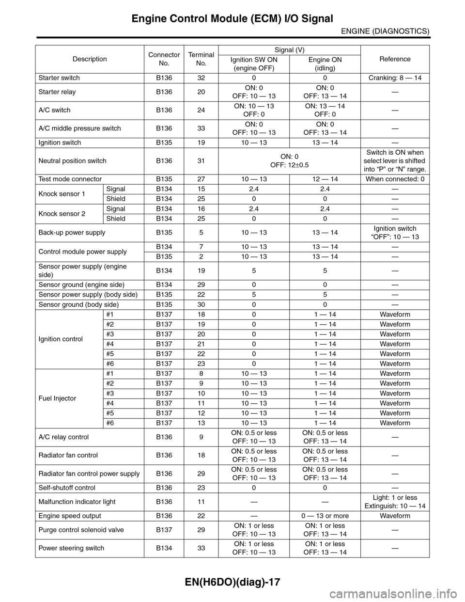
EN(H6DO)(diag)-17
Engine Control Module (ECM) I/O Signal
ENGINE (DIAGNOSTICS)
Starter switch B136 32 0 0 Cranking: 8 — 14
Starter relay B136 20ON: 0
OFF: 10 — 13
ON: 0
OFF: 13 — 14—
A/C switch B136 24ON: 10 — 13
OFF: 0
ON: 13 — 14
OFF: 0—
A/C middle pressure switch B136 33ON: 0
OFF: 10 — 13
ON: 0
OFF: 13 — 14—
Ignition switch B135 19 10 — 13 13 — 14 —
Neutral position switch B136 31ON: 0
OFF: 12±0.5
Switch is ON when
select lever is shifted
into “P” or “N” range.
Te s t m o d e c o n n e c t o r B 1 3 5 2 7 1 0 — 1 3 1 2 — 1 4 W h e n c o n n e c t e d : 0
Knock sensor 1Signal B134 15 2.4 2.4 —
Shield B134 25 0 0 —
Knock sensor 2Signal B134 16 2.4 2.4 —
Shield B134 25 0 0 —
Back-up power supply B135 5 10 — 13 13 — 14Ignition switch
“OFF”: 10 — 13
Control module power supplyB134 7 10 — 13 13 — 14 —
B135 2 10 — 13 13 — 14 —
Sensor power supply (engine
side)B134 19 5 5 —
Sensor ground (engine side) B134 29 0 0 —
Sensor power supply (body side) B135 22 5 5 —
Sensor ground (body side) B135 30 0 0 —
Ignition control
#1 B137 18 0 1 — 14 Waveform
#2 B137 19 0 1 — 14 Waveform
#3 B137 20 0 1 — 14 Waveform
#4 B137 21 0 1 — 14 Waveform
#5 B137 22 0 1 — 14 Waveform
#6 B137 23 0 1 — 14 Waveform
Fuel Injector
#1 B137 8 10 — 13 1 — 14 Waveform
#2 B137 9 10 — 13 1 — 14 Waveform
#3 B137 10 10 — 13 1 — 14 Waveform
#4 B137 11 10 — 13 1 — 14 Waveform
#5 B137 12 10 — 13 1 — 14 Waveform
#6 B137 13 10 — 13 1 — 14 Waveform
A/C relay control B136 9ON: 0.5 or less
OFF: 10 — 13
ON: 0.5 or less
OFF: 13 — 14—
Radiator fan control B136 18ON: 0.5 or less
OFF: 10 — 13
ON: 0.5 or less
OFF: 13 — 14—
Radiator fan control power supply B136 29ON: 0.5 or less
OFF: 10 — 13
ON: 0.5 or less
OFF: 13 — 14—
Self-shutoff control B136 23 0 0 —
Malfunction indicator light B136 11 — —Light: 1 or less
Extinguish: 10 — 14
Engine speed output B136 22 — 0 — 13 or more Waveform
Purge control solenoid valve B137 29ON: 1 or less
OFF: 10 — 13
ON: 1 or less
OFF: 13 — 14—
Pow er s te e r in g sw it c h B 1 3 4 33ON: 1 or less
OFF: 10 — 13
ON: 1 or less
OFF: 13 — 14—
DescriptionConnector
No.
Te r m i n a l
No.
Signal (V)
ReferenceIgnition SW ON
(engine OFF)
Engine ON
(idling)
Page 1179 of 2453
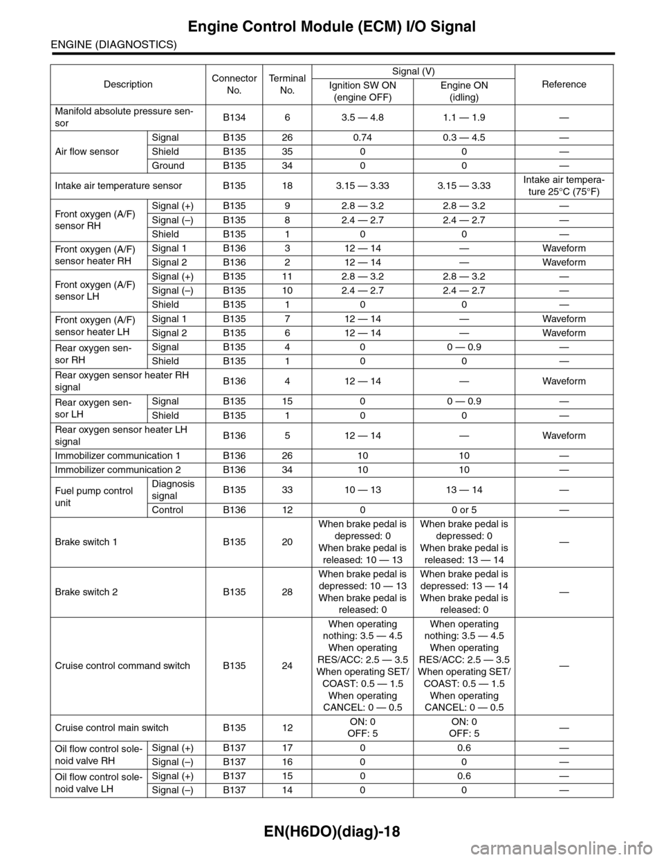
EN(H6DO)(diag)-18
Engine Control Module (ECM) I/O Signal
ENGINE (DIAGNOSTICS)
Manifold absolute pressure sen-
sorB134 6 3.5 — 4.8 1.1 — 1.9 —
Air flow sensor
Signal B135 26 0.74 0.3 — 4.5 —
Shield B135 35 0 0 —
Ground B135 34 0 0 —
Intake air temperature sensor B135 18 3.15 — 3.33 3.15 — 3.33Intake air tempera-
ture 25°C (75°F)
Fr o nt ox yg e n ( A / F)
sensor RH
Signal (+) B135 9 2.8 — 3.2 2.8 — 3.2 —
Signal (–) B135 8 2.4 — 2.7 2.4 — 2.7 —
Shield B135 1 0 0 —
Fr o nt ox yg e n ( A / F)
sensor heater RH
Signal 1 B136 3 12 — 14 — Waveform
Signal 2 B136 2 12 — 14 — Waveform
Fr o nt ox yg e n ( A / F)
sensor LH
Signal (+) B135 11 2.8 — 3.2 2.8 — 3.2 —
Signal (–) B135 10 2.4 — 2.7 2.4 — 2.7 —
Shield B135 1 0 0 —
Fr o nt ox yg e n ( A / F)
sensor heater LH
Signal 1 B135 7 12 — 14 — Waveform
Signal 2 B135 6 12 — 14 — Waveform
Rear oxygen sen-
sor RH
Signal B135 4 0 0 — 0.9 —
Shield B135 1 0 0 —
Rear oxygen sensor heater RH
signalB136 4 12 — 14 — Waveform
Rear oxygen sen-
sor LH
Signal B135 15 0 0 — 0.9 —
Shield B135 1 0 0 —
Rear oxygen sensor heater LH
signalB136 5 12 — 14 — Waveform
Immobilizer communication 1 B136 26 10 10 —
Immobilizer communication 2 B136 34 10 10 —
Fuel pump control
unit
Diagnosis
signalB135 33 10 — 13 13 — 14 —
Control B136 12 0 0 or 5 —
Brake switch 1 B135 20
When brake pedal is
depressed: 0
When brake pedal is
released: 10 — 13
When brake pedal is
depressed: 0
When brake pedal is
released: 13 — 14
—
Brake switch 2 B135 28
When brake pedal is
depressed: 10 — 13
When brake pedal is
released: 0
When brake pedal is
depressed: 13 — 14
When brake pedal is
released: 0
—
Cruise control command switch B135 24
When operating
nothing: 3.5 — 4.5
When operating
RES/ACC: 2.5 — 3.5
When operating SET/
COAST: 0.5 — 1.5
When operating
CANCEL: 0 — 0.5
When operating
nothing: 3.5 — 4.5
When operating
RES/ACC: 2.5 — 3.5
When operating SET/
COAST: 0.5 — 1.5
When operating
CANCEL: 0 — 0.5
—
Cruise control main switch B135 12ON: 0
OFF: 5
ON: 0
OFF: 5—
Oil flow control sole-
noid valve RH
Signal (+) B137 17 0 0.6 —
Signal (–) B137 16 0 0 —
Oil flow control sole-
noid valve LH
Signal (+) B137 15 0 0.6 —
Signal (–) B137 14 0 0 —
DescriptionConnector
No.
Te r m i n a l
No.
Signal (V)
ReferenceIgnition SW ON
(engine OFF)
Engine ON
(idling)
Page 1180 of 2453
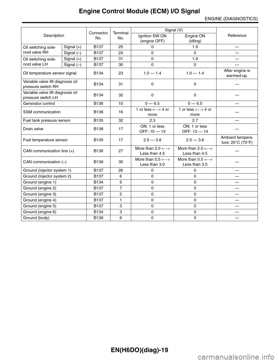
EN(H6DO)(diag)-19
Engine Control Module (ECM) I/O Signal
ENGINE (DIAGNOSTICS)
Oil switching sole-
noid valve RH
Signal (+) B137 25 0 1.9 —
Signal (–) B137 24 0 0 —
Oil switching sole-
noid valve LH
Signal (+) B137 31 0 1.9 —
Signal (–) B137 30 0 0 —
Oil temperature sensor signal B134 23 1.0 — 1.4 1.0 — 1.4After engine is
warmed-up.
Va r i a b l e va l v e l i f t d i a g n o s i s o i l
pressure switch RHB134 31 0 0 —
Va r i a b l e va l v e l i f t d i a g n o s i s o i l
pressure switch LHB134 32 0 0 —
Generator control B136 10 0 — 6.5 0 — 6.5 —
SSM communication B136 161 or less ←→ 4 or
more
1 or less ←→ 4 or
more—
Fuel tank pressure sensor B135 32 2.3 2.7 —
Drain valve B136 17ON: 1 or less
OFF: 10 — 13
ON: 1 or less
OFF: 13 — 14—
Fuel temperature sensor B135 17 2.5 — 3.8 2.5 — 3.8Ambient tempera-
ture: 25°C (75°F)
CAN communication line (+) B136 27More than 2.0 ←→
Less than 4.5
More than 2.0 ←→
Less than 4.5—
CAN communication (–) B136 35More than 0.5 ←→
Less than 3.0
More than 0.5 ←→
Less than 3.0—
Ground (injector system 1) B137 26 0 0 —
Ground (injector system 2) B137 6 0 0 —
Ground (engine 1) B134 5 0 0 —
Ground (engine 2) B137 7 0 0 —
Ground (engine 3) B137 2 0 0 —
Ground (engine 4) B137 1 0 0 —
Ground (engine 5) B137 3 0 0 —
Ground (engine 6) B134 3 0 0 —
Ground (body) B136 6 0 0 —
DescriptionConnector
No.
Te r m i n a l
No.
Signal (V)
ReferenceIgnition SW ON
(engine OFF)
Engine ON
(idling)
Page 1214 of 2453
EN(H6DO)(diag)-53
Malfunction Indicator Light
ENGINE (DIAGNOSTICS)
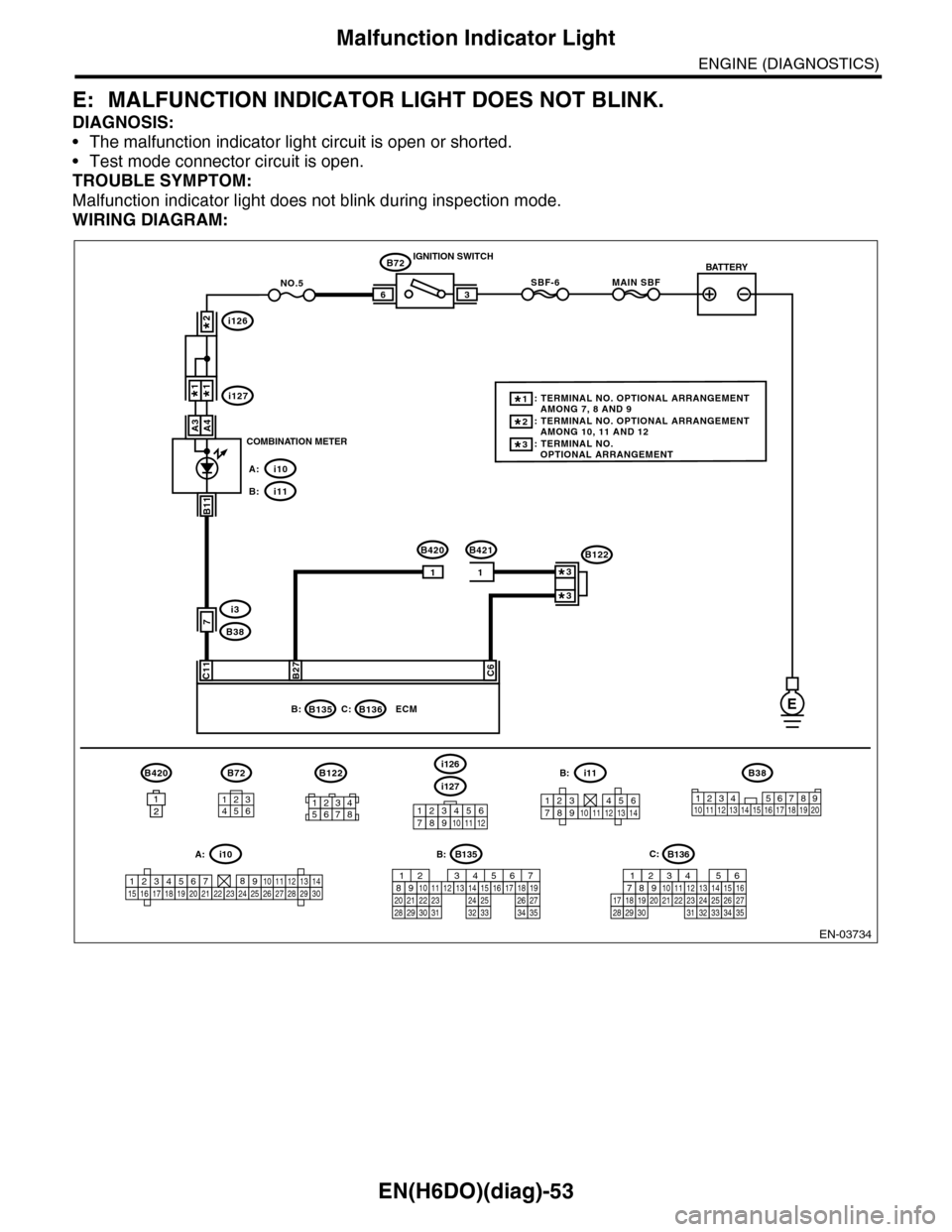
E: MALFUNCTION INDICATOR LIGHT DOES NOT BLINK.
DIAGNOSIS:
•The malfunction indicator light circuit is open or shorted.
•Test mode connector circuit is open.
TROUBLE SYMPTOM:
Malfunction indicator light does not blink during inspection mode.
WIRING DIAGRAM:
EN-03734
i126
i1271*1*
2*
i10A:
i11B:
BATTERY
3
B72
B420B421
IGNITION SWITCH
COMBINATION METER
B135B:
SBF-66
C11B27C6
ECM
B72
7
MAIN SBFNO.5
11
B420
1212
B11
i3
B38
E
A4A3
B136C:
134562
B38
1234 5678910 11 12 13 14 15 16 17 18 19 2012345678
B122
3*: TERMINAL NO. OPTIONAL ARRANGEMENT
2*: TERMINAL NO. OPTIONAL ARRANGEMENT AMONG 10, 11 AND 12
1*: TERMINAL NO. OPTIONAL ARRANGEMENT AMONG 7, 8 AND 9
B122
3*
3*
i127
i126
123456789101112
1234567891011121314
i11B:
123456789101112131415161718192021222324252627282930
i10A:B135
5672134
29
101112131415252416
30
98171819202821222332312627333435
B:B136
16101112131415252430
9871718192028212223293231
123456
2726333435
C:
Page 1215 of 2453
EN(H6DO)(diag)-54
Malfunction Indicator Light
ENGINE (DIAGNOSTICS)
Step Check Yes No
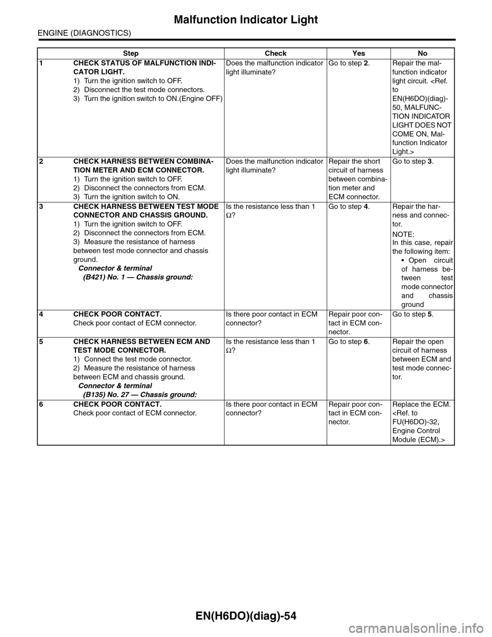
1CHECK STATUS OF MALFUNCTION INDI-
CATOR LIGHT.
1) Turn the ignition switch to OFF.
2) Disconnect the test mode connectors.
3) Turn the ignition switch to ON.(Engine OFF)
Does the malfunction indicator
light illuminate?
Go to step 2.Repair the mal-
function indicator
light circuit.
EN(H6DO)(diag)-
50, MALFUNC-
TION INDICATOR
LIGHT DOES NOT
COME ON, Mal-
function Indicator
Light.>
2CHECK HARNESS BETWEEN COMBINA-
TION METER AND ECM CONNECTOR.
1) Turn the ignition switch to OFF.
2) Disconnect the connectors from ECM.
3) Turn the ignition switch to ON.
Does the malfunction indicator
light illuminate?
Repair the short
circuit of harness
between combina-
tion meter and
ECM connector.
Go to step 3.
3CHECK HARNESS BETWEEN TEST MODE
CONNECTOR AND CHASSIS GROUND.
1) Turn the ignition switch to OFF.
2) Disconnect the connectors from ECM.
3) Measure the resistance of harness
between test mode connector and chassis
ground.
Connector & terminal
(B421) No. 1 — Chassis ground:
Is the resistance less than 1
Ω?
Go to step 4.Repair the har-
ness and connec-
tor.
NOTE:
In this case, repair
the following item:
•Open circuit
of harness be-
tween test
mode connector
and chassis
ground
4CHECK POOR CONTACT.
Check poor contact of ECM connector.
Is there poor contact in ECM
connector?
Repair poor con-
tact in ECM con-
nector.
Go to step 5.
5CHECK HARNESS BETWEEN ECM AND
TEST MODE CONNECTOR.
1) Connect the test mode connector.
2) Measure the resistance of harness
between ECM and chassis ground.
Connector & terminal
(B135) No. 27 — Chassis ground:
Is the resistance less than 1
Ω?
Go to step 6.Repair the open
circuit of harness
between ECM and
test mode connec-
tor.
6CHECK POOR CONTACT.
Check poor contact of ECM connector.
Is there poor contact in ECM
connector?
Repair poor con-
tact in ECM con-
nector.
Replace the ECM.
Engine Control
Module (ECM).>