2009 SUBARU TRIBECA Intake
[x] Cancel search: IntakePage 1915 of 2453
ME(H6DO)-49
Cam Sprocket
MECHANICAL
16.Cam Sprocket
A: REMOVAL
1) Remove the crank pulley.
2) Remove the front chain cover.
3) Remove the timing chain assembly.
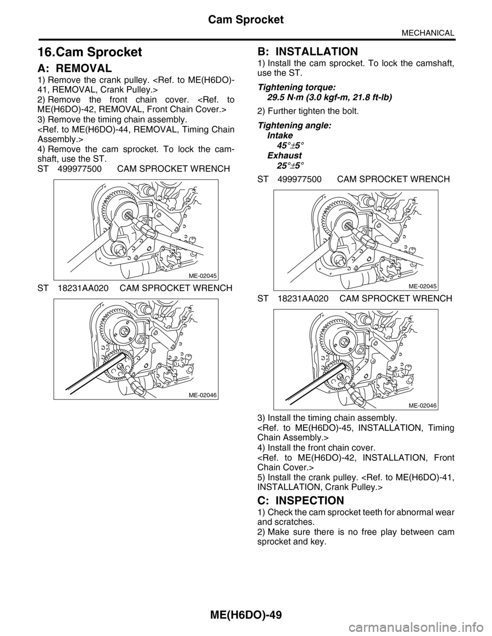
4) Remove the cam sprocket. To lock the cam-
shaft, use the ST.
ST 499977500 CAM SPROCKET WRENCH
ST 18231AA020 CAM SPROCKET WRENCH
B: INSTALLATION
1) Install the cam sprocket. To lock the camshaft,
use the ST.
Tightening torque:
29.5 N·m (3.0 kgf-m, 21.8 ft-lb)
2) Further tighten the bolt.
Tightening angle:
Intake
45°±5°
Exhaust
25°±5°
ST 499977500 CAM SPROCKET WRENCH
ST 18231AA020 CAM SPROCKET WRENCH
3) Install the timing chain assembly.
4) Install the front chain cover.
5) Install the crank pulley.
C: INSPECTION
1) Check the cam sprocket teeth for abnormal wear
and scratches.
2) Make sure there is no free play between cam
sprocket and key.
ME-02045
ME-02046
ME-02045
ME-02046
Page 1922 of 2453
ME(H6DO)-56
Camshaft
MECHANICAL
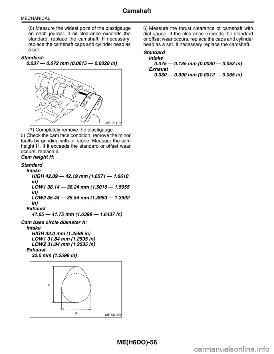
(6) Measure the widest point of the plastigauge
on each journal. If oil clearance exceeds the
standard, replace the camshaft. If necessary,
replace the camshaft caps and cylinder head as
a set.
Standard:
0.037 — 0.072 mm (0.0015 — 0.0028 in)
(7) Completely remove the plastigauge.
5) Check the cam face condition; remove the minor
faults by grinding with oil stone. Measure the cam
height H. If it exceeds the standard or offset wear
occurs, replace it.
Cam height H:
Standard
Intake
HIGH 42.09 — 42.19 mm (1.6571 — 1.6610
in)
LOW1 38.14 — 38.24 mm (1.5016 — 1.5055
in)
LOW2 35.44 — 35.54 mm (1.3953 — 1.3992
in)
Exhaust
41.65 — 41.75 mm (1.6398 — 1.6437 in)
Cam base circle diameter A:
Intake
HIGH 32.0 mm (1.2598 in)
LOW1 31.84 mm (1.2535 in)
LOW2 31.84 mm (1.2535 in)
Exhaust
32.0 mm (1.2598 in)
6) Measure the thrust clearance of camshaft with
dial gauge. If the clearance exceeds the standard
or offset wear occurs, replace the caps and cylinder
head as a set. If necessary replace the camshaft.
Standard
Intake
0.075 — 0.135 mm (0.0030 — 0.053 in)
Exhaust
0.030 — 0.090 mm (0.0012 — 0.035 in)
ME-00119
ME-00120
H
A
Page 1924 of 2453
ME(H6DO)-58
Cylinder Head
MECHANICAL
8) Install the front chain cover.
9) Install the crank pulley.
C: DISASSEMBLY
1) Set the cylinder head on ST.
ST 18250AA010 CYLINDER HEAD TABLE
2) Remove the valve lifter.
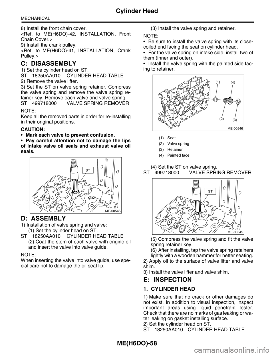
3) Set the ST on valve spring retainer. Compress
the valve spring and remove the valve spring re-
tainer key. Remove each valve and valve spring.
ST 499718000 VALVE SPRING REMOVER
NOTE:
Keep all the removed parts in order for re-installing
in their original positions.
CAUTION:
•Mark each valve to prevent confusion.
•Pay careful attention not to damage the lips
of intake valve oil seals and exhaust valve oil
seals.
D: ASSEMBLY
1) Installation of valve spring and valve:
(1) Set the cylinder head on ST.
ST 18250AA010 CYLINDER HEAD TABLE
(2) Coat the stem of each valve with engine oil
and insert the valve into valve guide.
NOTE:
When inserting the valve into valve guide, use spe-
cial care not to damage the oil seal lip.
(3) Install the valve spring and retainer.
NOTE:
•Be sure to install the valve spring with its close-
coiled end facing the seat on cylinder head.
•For the valve spring on intake side, install two of
them (inner and outer).
•Install the valve spring with the painted side fac-
ing to retainer.
(4) Set the ST on valve spring.
ST 499718000 VALVE SPRING REMOVER
(5) Compress the valve spring and fit the valve
spring retainer key.
(6) After installing, tap the valve spring retainers
lightly with a wooden hammer for better seating.
2) Apply oil to the surface of valve lifter and valve
shim.
3) Install the valve lifter and valve shim.
E: INSPECTION
1. CYLINDER HEAD
1) Make sure that no crack or other damages do
not exist. In addition to visual inspection, inspect
important areas using liquid penetrant tester.
Check that there are no marks of gas leaking or wa-
ter leaking on gasket installing surface.
2) Set the cylinder head on ST.
ST 18250AA010 CYLINDER HEAD TABLE
ST
ME-00545
(1) Seat
(2) Valve spring
(3) Retainer
(4) Painted face
(1)
(2)(3)
(4)
ME-00546
ST
ME-00545
Page 1925 of 2453
ME(H6DO)-59
Cylinder Head
MECHANICAL
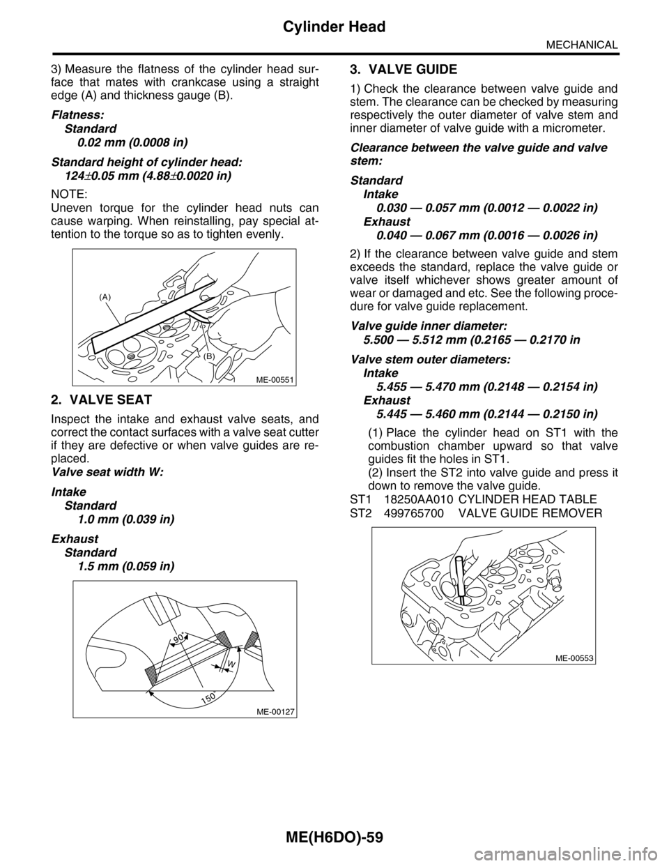
3) Measure the flatness of the cylinder head sur-
face that mates with crankcase using a straight
edge (A) and thickness gauge (B).
Flatness:
Standard
0.02 mm (0.0008 in)
Standard height of cylinder head:
124±0.05 mm (4.88±0.0020 in)
NOTE:
Uneven torque for the cylinder head nuts can
cause warping. When reinstalling, pay special at-
tention to the torque so as to tighten evenly.
2. VALVE SEAT
Inspect the intake and exhaust valve seats, and
correct the contact surfaces with a valve seat cutter
if they are defective or when valve guides are re-
placed.
Valve seat width W:
Intake
Standard
1.0 mm (0.039 in)
Exhaust
Standard
1.5 mm (0.059 in)
3. VALVE GUIDE
1) Check the clearance between valve guide and
stem. The clearance can be checked by measuring
respectively the outer diameter of valve stem and
inner diameter of valve guide with a micrometer.
Clearance between the valve guide and valve
stem:
Standard
Intake
0.030 — 0.057 mm (0.0012 — 0.0022 in)
Exhaust
0.040 — 0.067 mm (0.0016 — 0.0026 in)
2) If the clearance between valve guide and stem
exceeds the standard, replace the valve guide or
valve itself whichever shows greater amount of
wear or damaged and etc. See the following proce-
dure for valve guide replacement.
Valve guide inner diameter:
5.500 — 5.512 mm (0.2165 — 0.2170 in
Valve stem outer diameters:
Intake
5.455 — 5.470 mm (0.2148 — 0.2154 in)
Exhaust
5.445 — 5.460 mm (0.2144 — 0.2150 in)
(1) Place the cylinder head on ST1 with the
combustion chamber upward so that valve
guides fit the holes in ST1.
(2) Insert the ST2 into valve guide and press it
down to remove the valve guide.
ST1 18250AA010 CYLINDER HEAD TABLE
ST2 499765700 VALVE GUIDE REMOVER
(A)
(B)
ME-00551
ME-00127
WME-00553
Page 1926 of 2453
ME(H6DO)-60
Cylinder Head
MECHANICAL
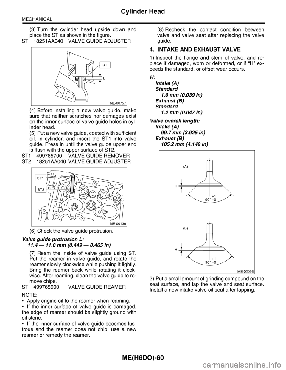
(3) Turn the cylinder head upside down and
place the ST as shown in the figure.
ST 18251AA040 VALVE GUIDE ADJUSTER
(4) Before installing a new valve guide, make
sure that neither scratches nor damages exist
on the inner surface of valve guide holes in cyl-
inder head.
(5) Put a new valve guide, coated with sufficient
oil, in cylinder, and insert the ST1 into valve
guide. Press in until the valve guide upper end
is flush with the upper surface of ST2.
ST1 499765700 VALVE GUIDE REMOVER
ST2 18251AA040 VALVE GUIDE ADJUSTER
(6) Check the valve guide protrusion.
Valve guide protrusion L:
11.4 — 11.8 mm (0.449 — 0.465 in)
(7) Ream the inside of valve guide using ST.
Put the reamer in valve guide, and rotate the
reamer slowly clockwise while pushing it lightly.
Bring the reamer back while rotating it clock-
wise. After reaming, clean the valve guide to re-
move chips.
ST 499765900 VALVE GUIDE REAMER
NOTE:
•Apply engine oil to the reamer when reaming.
•If the inner surface of valve guide is damaged,
the edge of reamer should be slightly ground with
oil stone.
•If the inner surface of valve guide becomes lus-
trous and the reamer does not chip, use a new
reamer or remedy the reamer.
(8) Recheck the contact condition between
valve and valve seat after replacing the valve
guide.
4. INTAKE AND EXHAUST VALVE
1) Inspect the flange and stem of valve, and re-
place if damaged, worn or deformed, or if “H” ex-
ceeds the standard, or offset wear occurs.
H:
Intake (A)
Standard
1.0 mm (0.039 in)
Exhaust (B)
Standard
1.2 mm (0.047 in)
Valve overall length:
Intake (A)
99.7 mm (3.925 in)
Exhaust (B)
105.2 mm (4.142 in)
2) Put a small amount of grinding compound on the
seat surface, and lap the valve and seat surface.
Install a new intake valve oil seal after lapping.
ME-00757
ST
L
ME-00130
ST1
ST2
ME-02096
H
H
(B)
(A)
90 0+1
90 0+1
Page 1927 of 2453
ME(H6DO)-61
Cylinder Head
MECHANICAL
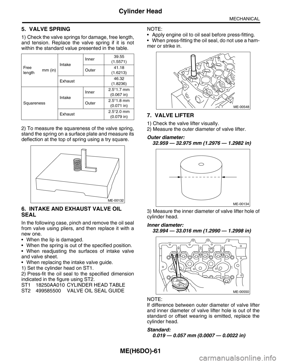
5. VALVE SPRING
1) Check the valve springs for damage, free length,
and tension. Replace the valve spring if it is not
within the standard value presented in the table.
2) To measure the squareness of the valve spring,
stand the spring on a surface plate and measure its
deflection at the top of spring using a try square.
6. INTAKE AND EXHAUST VALVE OIL
SEAL
In the following case, pinch and remove the oil seal
from valve using pliers, and then replace it with a
new one.
•When the lip is damaged.
•When the spring is out of the specified position.
•When readjusting the surfaces of intake valve
and valve sheet.
•When replacing the intake valve guide.
1) Set the cylinder head on ST1.
2) Press-fit the oil seal to the specified dimension
indicated in the figure using ST2.
ST1 18250AA010 CYLINDER HEAD TABLE
ST2 499585500 VALVE OIL SEAL GUIDE
NOTE:
•Apply engine oil to oil seal before press-fitting.
•When press-fitting the oil seal, do not use a ham-
mer or strike in.
7. VALVE LIFTER
1) Check the valve lifter visually.
2) Measure the outer diameter of valve lifter.
Outer diameter:
32.959 — 32.975 mm (1.2976 — 1.2982 in)
3) Measure the inner diameter of valve lifter hole of
cylinder head.
Inner diameter:
32.994 — 33.016 mm (1.2990 — 1.2998 in)
NOTE:
If difference between outer diameter of valve lifter
and inner diameter of valve lifter hole is out of the
standard or offset wearing is emitted, replace the
cylinder head.
Standard:
0.019 — 0.057 mm (0.0007 — 0.0022 in)
Fr e e
lengthmm (in)
Intake
Inner39.55
(1.5571)
Outer41.18
(1.6213)
Exhaust46.32
(1.8236)
Squareness
Intake
Inner2.5°1.7 mm
(0.067 in)
Outer2.5°1.8 mm
(0.071 in)
Exhaust2.5°2.0 mm
(0.079 in)
ME-00132
ME-00548
ME-00134
ME-00550
Page 1944 of 2453
ME(H6DO)-78
Oil Switching Solenoid Valve
MECHANICAL
23.Oil Switching Solenoid Valve
A: REMOVAL
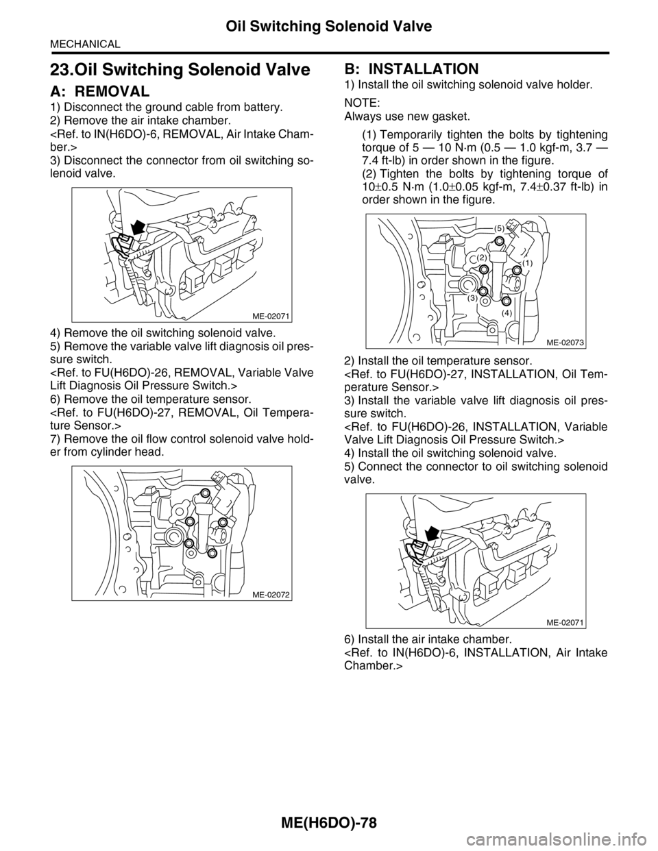
1) Disconnect the ground cable from battery.
2) Remove the air intake chamber.
3) Disconnect the connector from oil switching so-
lenoid valve.
4) Remove the oil switching solenoid valve.
5) Remove the variable valve lift diagnosis oil pres-
sure switch.
6) Remove the oil temperature sensor.
7) Remove the oil flow control solenoid valve hold-
er from cylinder head.
B: INSTALLATION
1) Install the oil switching solenoid valve holder.
NOTE:
Always use new gasket.
(1) Temporarily tighten the bolts by tightening
torque of 5 — 10 N·m (0.5 — 1.0 kgf-m, 3.7 —
7.4 ft-lb) in order shown in the figure.
(2) Tighten the bolts by tightening torque of
10±0.5 N·m (1.0±0.05 kgf-m, 7.4±0.37 ft-lb) in
order shown in the figure.
2) Install the oil temperature sensor.
3) Install the variable valve lift diagnosis oil pres-
sure switch.
4) Install the oil switching solenoid valve.
5) Connect the connector to oil switching solenoid
valve.
6) Install the air intake chamber.
ME-02071
ME-02072
ME-02073
(2)(1)
(5)
(4)
(3)
ME-02071
Page 1945 of 2453
ME(H6DO)-79
Intake and Exhaust Valve
MECHANICAL
24.Intake and Exhaust Valve
A: SPECIFICATION
Refer to “Cylinder Head” for removal and installa-
tion procedures of intake and exhaust valves