2009 SUBARU TRIBECA engine coolant
[x] Cancel search: engine coolantPage 455 of 2453
IDI-16
Engine Coolant Temperature Gauge
INSTRUMENTATION/DRIVER INFO
7. Engine Coolant Temperature
Gauge
A: SPECIFICATION
Since the meter case assembly cannot be disas-
sembled, do not remove or inspect the temperature
gauge alone. (Do not remove the cover on the back
side.)
Page 459 of 2453

LAN(diag)-3
Check List for Interview
LAN SYSTEM (DIAGNOSTICS)
2. Check List for Interview
A: CHECK
Inspect the following item about the vehicle’s state.
1. DISPLAY OF COMMUNICATION ERROR
2. DISPLAY IN COMBINATION METER
Communication error is
displayed in odo/trip meter.
When and how often are they displayed?
Always
Sometimes
Only once
Which communication error is displayed? (Record them all)
Er IU (Fail in the body integrated unit)
Er HC (Fail of high-speed CAN)
Er LC (Fail of low-speed CAN)
Er –– (Fails of both high-speed and low-speed CAN)
Er EG (Fail of EGI communication data)
Er TC (fail of TCM communication data)
Er Ab (Fail of vehicle dynamics control (VDC)/ABS communication data)
Er bb (Fail of brake vacuum system)
Ignition key position OFF
ACC
ON (Before starting engine)
START
ON (After starting Engine, engine is running)
ON (After starting Engine, engine is at a standstill)
Timing Immediately after turning the ignition to ON.
Immediately after turning the ignition to START.
Display in combination
meter
a) Display of engine coolant temperature gauge OK / NG
b) Display of fuel gauge OK / NG
Display of other indicators c) Malfunction indicator light ON / OFF
d) SPORT indicator light (AT warning light) ON / OFF
e) ABS warning light/Vehicle dynamics control (VDC) warning
light ON / OFF
f) Security indicator light ON / Blink / OFF
g) Seat belt warning light (Driver’s seat) ON / OFF
h) Seat belt warning light (Passenger’s seat) ON / OFF
Page 532 of 2453

LAN(diag)-76
General Diagnostic Table
LAN SYSTEM (DIAGNOSTICS)
13.General Diagnostic Table
A: INSPECTION
Read the DTC or inspect and diagnose the following data in the current data display using Subaru Select
Monitor.
1. LAN SYSTEM
Item OperationSpecificationsNoteYES NO
Diagnostic codeDTC is not displayed when inspect-
ing all DTCs.
DTC is not dis-
played.
Perfor m the diag-
nosis according to
DTC.
Refer to the DTC table
when there are trouble
codes of the CAN commu-
nication system for a mul-
tiple of modules.
TION CHECK, DTC
TA B L E , L i s t o f D i a g n o s t i c
Tr o u b l e C o d e ( D T C ) . >
Coolant Temp.
Check the current data display of
ECM, TCM and body integrated
unit. Three data value are the
same.
Same valuesInspect LAN sys-
tem.
If engine coolant tempera-
ture sensor is not OK,
inspect the sensor circuit.
R defogger SWIt turns to ON when pressing
switch. (Low-speed CAN is OK)Tu r n s t o O N .Inspect rear defog-
ger switch.
Rear defogger switch is
connected with Low-
speed CAN.
R defogger output When switch input, it is output. OutputReplace the body
integrated unit.
If not operating with out-
put, check the rear defog-
ger relay.
Door lock SWWhen locked with door lock switch,
it turns to ON.Tu r n s t o O N .Inspect door lock
switch.
Door lock actuatorWhen locked with door lock switch,
it is output.OutputReplace the body
integrated unit.—
Page 1017 of 2453
VDC(diag)-25
Warning Light Illumination Pattern
VEHICLE DYNAMICS CONTROL (VDC) (DIAGNOSTICS)
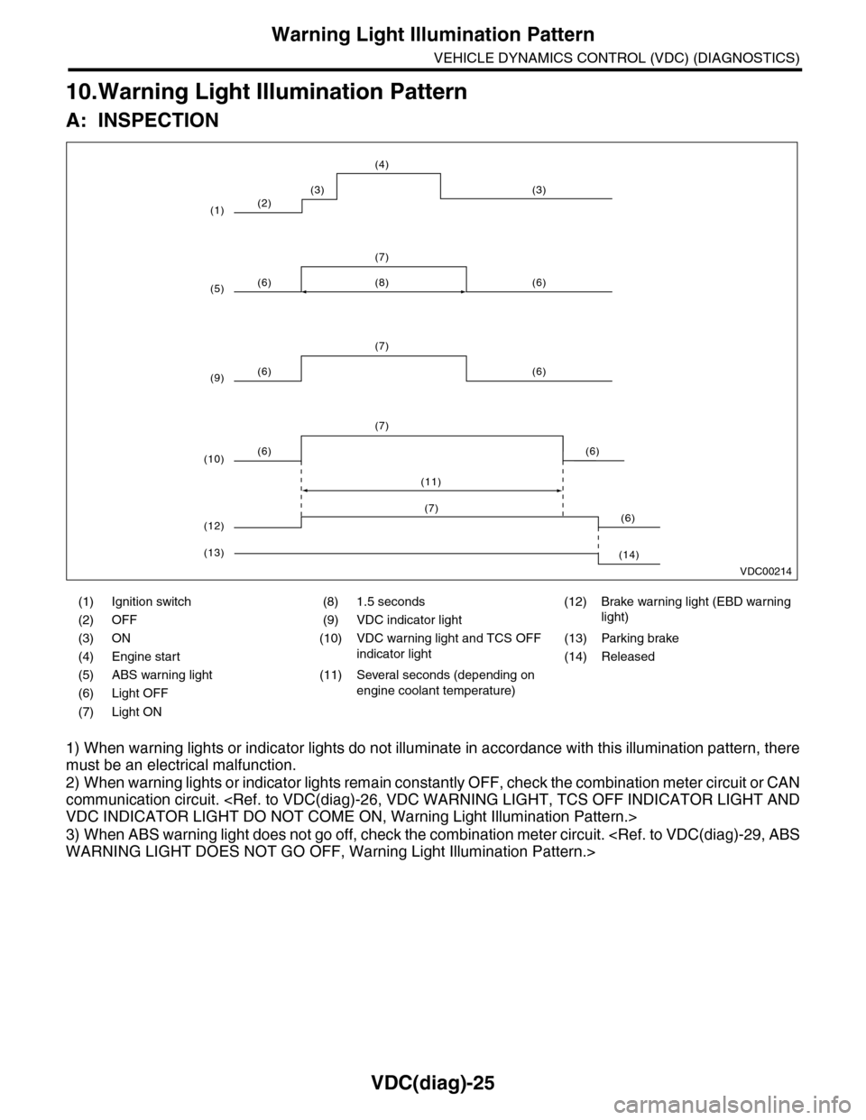
10.Warning Light Illumination Pattern
A: INSPECTION
1) When warning lights or indicator lights do not illuminate in accordance with this illumination pattern, there
must be an electrical malfunction.
2) When warning lights or indicator lights remain constantly OFF, check the combination meter circuit or CAN
communication circuit.
3) When ABS warning light does not go off, check the combination meter circuit.
(1) Ignition switch (8) 1.5 seconds (12) Brake warning light (EBD warning
light)(2) OFF (9) VDC indicator light
(3) ON (10) VDC warning light and TCS OFF
indicator light
(13) Parking brake
(4) Engine start (14) Released
(5) ABS warning light (11) Several seconds (depending on
engine coolant temperature)(6) Light OFF
(7) Light ON
VDC00214
(2)
(6) (6)
(7)
(6) (6)
(7)
(8)
(6) (6)
(7)
(11)
(3) (3)
(4)
(1)
(5)
(9)
(10)
(6)(7)
(12)
(14)(13)
Page 1018 of 2453
VDC(diag)-26
Warning Light Illumination Pattern
VEHICLE DYNAMICS CONTROL (VDC) (DIAGNOSTICS)
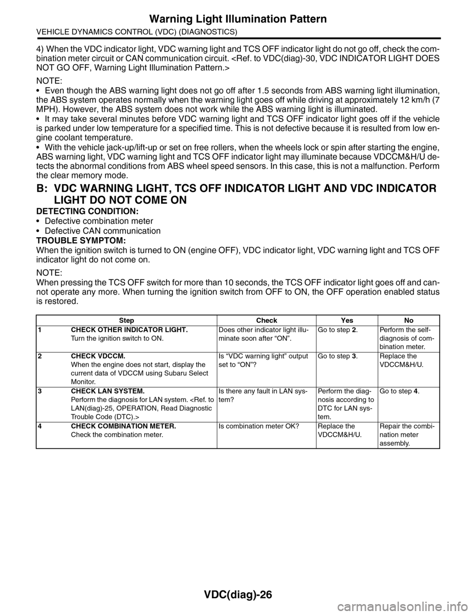
4) When the VDC indicator light, VDC warning light and TCS OFF indicator light do not go off, check the com-
bination meter circuit or CAN communication circuit.
NOTE:
•Even though the ABS warning light does not go off after 1.5 seconds from ABS warning light illumination,
the ABS system operates normally when the warning light goes off while driving at approximately 12 km/h (7
MPH). However, the ABS system does not work while the ABS warning light is illuminated.
•It may take several minutes before VDC warning light and TCS OFF indicator light goes off if the vehicle
is parked under low temperature for a specified time. This is not defective because it is resulted from low en-
gine coolant temperature.
•With the vehicle jack-up/lift-up or set on free rollers, when the wheels lock or spin after starting the engine,
ABS warning light, VDC warning light and TCS OFF indicator light may illuminate because VDCCM&H/U de-
tects the abnormal conditions from ABS wheel speed sensors. In this case, this is not a malfunction. Perform
the clear memory mode.
B: VDC WARNING LIGHT, TCS OFF INDICATOR LIGHT AND VDC INDICATOR
LIGHT DO NOT COME ON
DETECTING CONDITION:
•Defective combination meter
•Defective CAN communication
TROUBLE SYMPTOM:
When the ignition switch is turned to ON (engine OFF), VDC indicator light, VDC warning light and TCS OFF
indicator light do not come on.
NOTE:
When pressing the TCS OFF switch for more than 10 seconds, the TCS OFF indicator light goes off and can-
not operate any more. When turning the ignition switch from OFF to ON, the OFF operation enabled status
is restored.
Step Check Yes No
1CHECK OTHER INDICATOR LIGHT.
Tu r n t h e i g n i t i o n s w i t c h t o O N .
Does other indicator light illu-
minate soon after “ON”.
Go to step 2.Perform the self-
diagnosis of com-
bination meter.
2CHECK VDCCM.
When the engine does not start, display the
current data of VDCCM using Subaru Select
Monitor.
Is “VDC warning light” output
set to “ON”?
Go to step 3.Replace the
VDCCM&H/U.
3CHECK LAN SYSTEM.
Perfor m the diagnosis for LAN system.
Tr o u b l e C o d e ( D T C ) . >
Is there any fault in LAN sys-
tem?
Pe r for m t h e d ia g -
nosis according to
DTC for LAN sys-
tem.
Go to step 4.
4CHECK COMBINATION METER.
Check the combination meter.
Is combination meter OK? Replace the
VDCCM&H/U.
Repair the combi-
nation meter
assembly.
Page 1023 of 2453
VDC(diag)-31
Warning Light Illumination Pattern
VEHICLE DYNAMICS CONTROL (VDC) (DIAGNOSTICS)
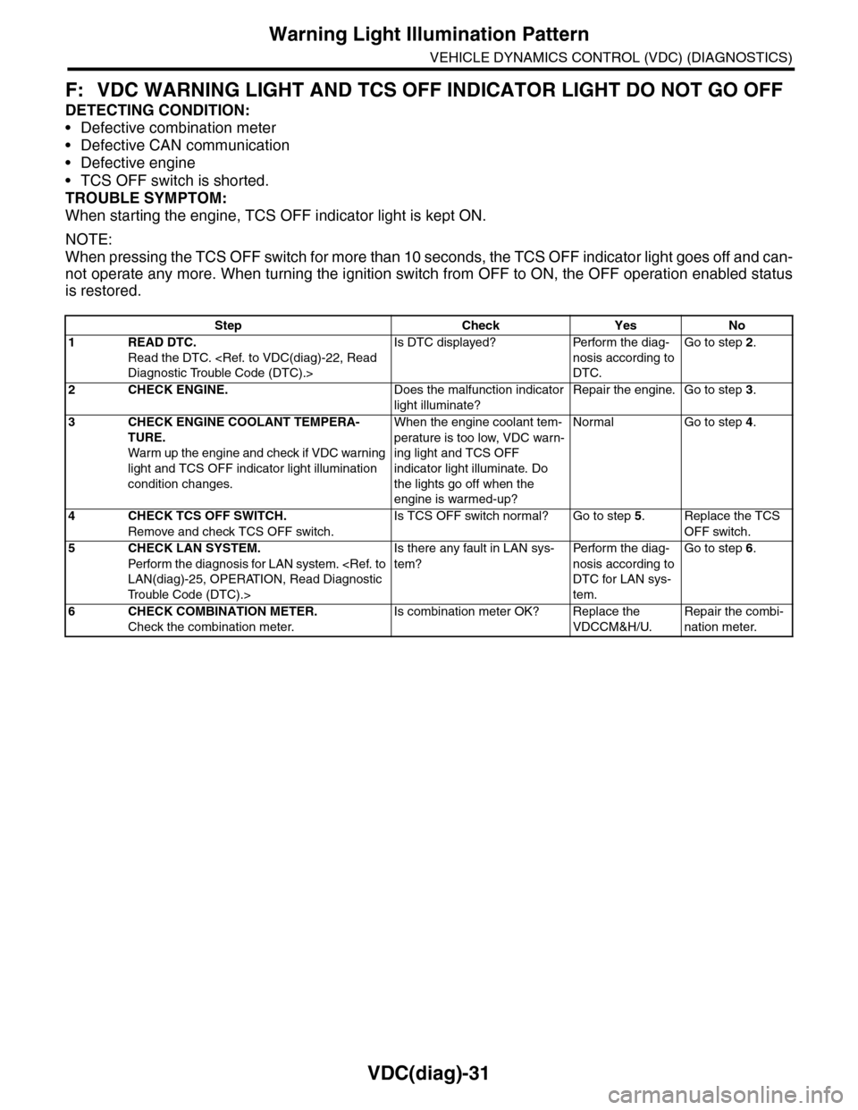
F: VDC WARNING LIGHT AND TCS OFF INDICATOR LIGHT DO NOT GO OFF
DETECTING CONDITION:
•Defective combination meter
•Defective CAN communication
•Defective engine
•TCS OFF switch is shorted.
TROUBLE SYMPTOM:
When starting the engine, TCS OFF indicator light is kept ON.
NOTE:
When pressing the TCS OFF switch for more than 10 seconds, the TCS OFF indicator light goes off and can-
not operate any more. When turning the ignition switch from OFF to ON, the OFF operation enabled status
is restored.
Step Check Yes No
1READ DTC.
Read the DTC.
Is DTC displayed? Perform the diag-
nosis according to
DTC.
Go to step 2.
2CHECK ENGINE.Does the malfunction indicator
light illuminate?
Repair the engine. Go to step 3.
3CHECK ENGINE COOLANT TEMPERA-
TURE.
War m up the engine and check if VDC war ning
light and TCS OFF indicator light illumination
condition changes.
When the engine coolant tem-
perature is too low, VDC warn-
ing light and TCS OFF
indicator light illuminate. Do
the lights go off when the
engine is warmed-up?
Normal Go to step 4.
4CHECK TCS OFF SWITCH.
Remove and check TCS OFF switch.
Is TCS OFF switch normal? Go to step 5.Replace the TCS
OFF switch.
5CHECK LAN SYSTEM.
Perfor m the diagnosis for LAN system.
Tr o u b l e C o d e ( D T C ) . >
Is there any fault in LAN sys-
tem?
Pe r for m t h e d ia g -
nosis according to
DTC for LAN sys-
tem.
Go to step 6.
6CHECK COMBINATION METER.
Check the combination meter.
Is combination meter OK? Replace the
VDCCM&H/U.
Repair the combi-
nation meter.
Page 1121 of 2453
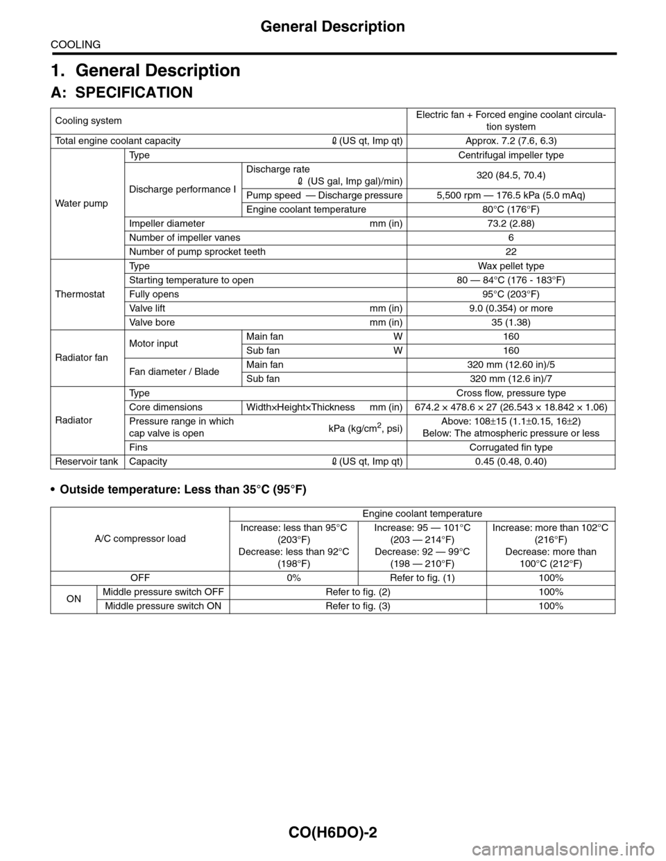
CO(H6DO)-2
General Description
COOLING
1. General Description
A: SPECIFICATION
•Outside temperature: Less than 35°C (95°F)
Cooling systemElectric fan + Forced engine coolant circula-
tion system
To t a l e n g i n e c o o l a n t c a p a c i t y2(US qt, Imp qt) Approx. 7.2 (7.6, 6.3)
Wa t er p u mp
Ty p e C e n t r i f u g a l i m p e l l e r t y p e
Discharge performance I
Discharge rate
2 (US gal, Imp gal)/min)320 (84.5, 70.4)
Pump speed — Discharge pressure 5,500 rpm — 176.5 kPa (5.0 mAq)
Engine coolant temperature 80°C (176°F)
Impeller diameter mm (in) 73.2 (2.88)
Number of impeller vanes 6
Number of pump sprocket teeth 22
Thermostat
Ty p eWa x p el l et t yp e
Starting temperature to open 80 — 84°C (176 - 183°F)
Fully opens 95°C (203°F)
Va l ve l i f t m m ( i n ) 9 . 0 ( 0 . 3 5 4 ) o r m o r e
Va l ve b o r e m m ( i n ) 3 5 ( 1 . 3 8 )
Radiator fan
Motor inputMain fan W 160
Sub fan W 160
Fan di a me t er / B la deMain fan 320 mm (12.60 in)/5
Sub fan 320 mm (12.6 in)/7
Radiator
Ty p e C r o s s f l o w , p r e s s u r e t y p e
Core dimensions Width×Height×Thickness mm (in) 674.2 × 478.6 × 27 (26.543 × 18.842 × 1.06)
Pressure range in which
cap valve is openkPa (kg/cm2, psi)Above: 108±15 (1.1±0.15, 16±2)
Below: The atmospheric pressure or less
FinsCorrugated fin type
Reservoir tank Capacity2(US qt, Imp qt) 0.45 (0.48, 0.40)
A/C compressor load
Engine coolant temperature
Increase: less than 95°C
(203°F)
Decrease: less than 92°C
(198°F)
Increase: 95 — 101°C
(203 — 214°F)
Decrease: 92 — 99°C
(198 — 210°F)
Increase: more than 102°C
(216°F)
Decrease: more than
100°C (212°F)
OFF 0% Refer to fig. (1) 100%
ONMiddle pressure switch OFF Refer to fig. (2) 100%
Middle pressure switch ON Refer to fig. (3) 100%
Page 1122 of 2453
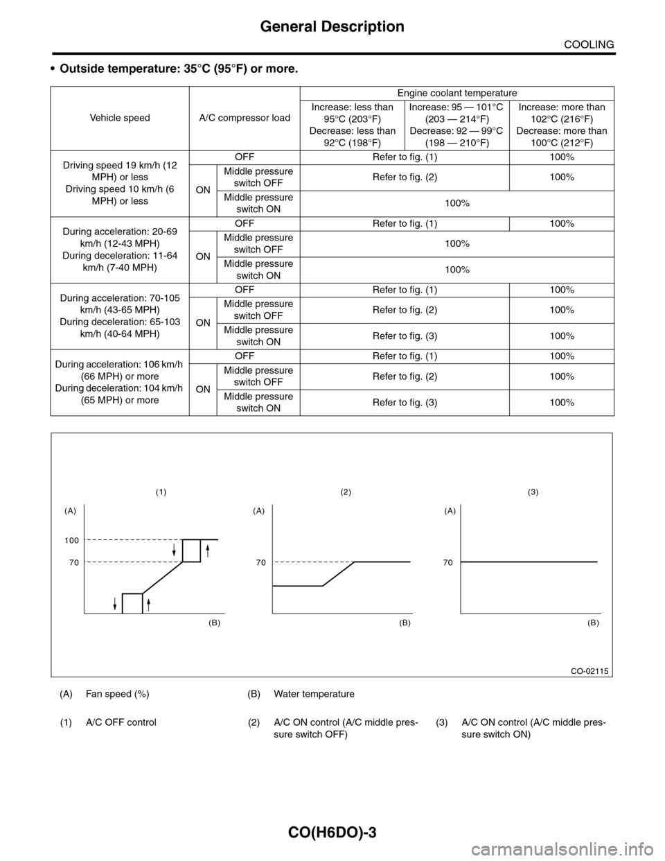
CO(H6DO)-3
General Description
COOLING
•Outside temperature: 35°C (95°F) or more.
Ve h i c l e s p e e d A / C c o m p r e s s o r l o a d
Engine coolant temperature
Increase: less than
95°C (203°F)
Decrease: less than
92°C (198°F)
Increase: 95 — 101°C
(203 — 214°F)
Decrease: 92 — 99°C
(198 — 210°F)
Increase: more than
102°C (216°F)
Decrease: more than
100°C (212°F)
Driving speed 19 km/h (12
MPH) or less
Driving speed 10 km/h (6
MPH) or less
OFF Refer to fig. (1) 100%
ON
Middle pressure
switch OFFRefer to fig. (2) 100%
Middle pressure
switch ON100%
During acceleration: 20-69
km/h (12-43 MPH)
During deceleration: 11-64
km/h (7-40 MPH)
OFF Refer to fig. (1) 100%
ON
Middle pressure
switch OFF100%
Middle pressure
switch ON100%
During acceleration: 70-105
km/h (43-65 MPH)
During deceleration: 65-103
km/h (40-64 MPH)
OFF Refer to fig. (1) 100%
ON
Middle pressure
switch OFFRefer to fig. (2) 100%
Middle pressure
switch ONRefer to fig. (3) 100%
During acceleration: 106 km/h
(66 MPH) or more
During deceleration: 104 km/h
(65 MPH) or more
OFF Refer to fig. (1) 100%
ON
Middle pressure
switch OFFRefer to fig. (2) 100%
Middle pressure
switch ONRefer to fig. (3) 100%
(A) Fan speed (%) (B) Water temperature
(1) A/C OFF control (2) A/C ON control (A/C middle pres-
sure switch OFF)
(3) A/C ON control (A/C middle pres-
sure switch ON)
CO-02115
100
(1)
70
(A)
(B)
(2)
70
(A)
(B)
(3)
70
(A)
(B)