Page 1904 of 2453

ME(H6DO)-38
Engine Assembly
MECHANICAL
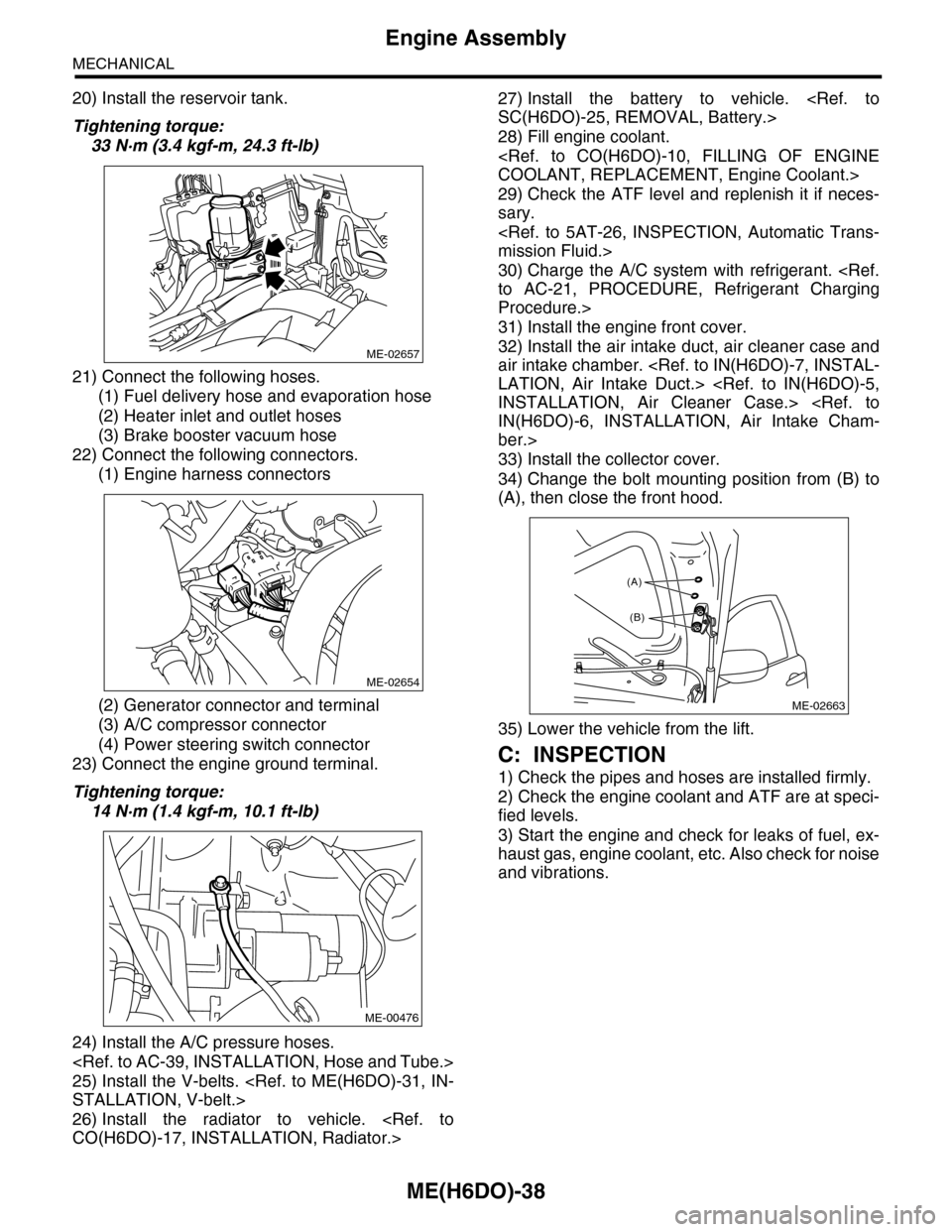
20) Install the reservoir tank.
Tightening torque:
33 N·m (3.4 kgf-m, 24.3 ft-lb)
21) Connect the following hoses.
(1) Fuel delivery hose and evaporation hose
(2) Heater inlet and outlet hoses
(3) Brake booster vacuum hose
22) Connect the following connectors.
(1) Engine harness connectors
(2) Generator connector and terminal
(3) A/C compressor connector
(4) Power steering switch connector
23) Connect the engine ground terminal.
Tightening torque:
14 N·m (1.4 kgf-m, 10.1 ft-lb)
24) Install the A/C pressure hoses.
25) Install the V-belts.
STALLATION, V-belt.>
26) Install the radiator to vehicle.
CO(H6DO)-17, INSTALLATION, Radiator.>
27) Install the battery to vehicle.
SC(H6DO)-25, REMOVAL, Battery.>
28) Fill engine coolant.
COOLANT, REPLACEMENT, Engine Coolant.>
29) Check the ATF level and replenish it if neces-
sary.
mission Fluid.>
30) Charge the A/C system with refrigerant.
to AC-21, PROCEDURE, Refrigerant Charging
Procedure.>
31) Install the engine front cover.
32) Install the air intake duct, air cleaner case and
air intake chamber.
LATION, Air Intake Duct.>
INSTALLATION, Air Cleaner Case.>
IN(H6DO)-6, INSTALLATION, Air Intake Cham-
ber.>
33) Install the collector cover.
34) Change the bolt mounting position from (B) to
(A), then close the front hood.
35) Lower the vehicle from the lift.
C: INSPECTION
1) Check the pipes and hoses are installed firmly.
2) Check the engine coolant and ATF are at speci-
fied levels.
3) Start the engine and check for leaks of fuel, ex-
haust gas, engine coolant, etc. Also check for noise
and vibrations.
ME-02657
ME-02654
ME-00476
ME-02663
(A)
(B)
Page 1949 of 2453

ME(H6DO)-83
Engine Trouble in General
MECHANICAL
28.Engine Trouble in General
A: INSPECTION
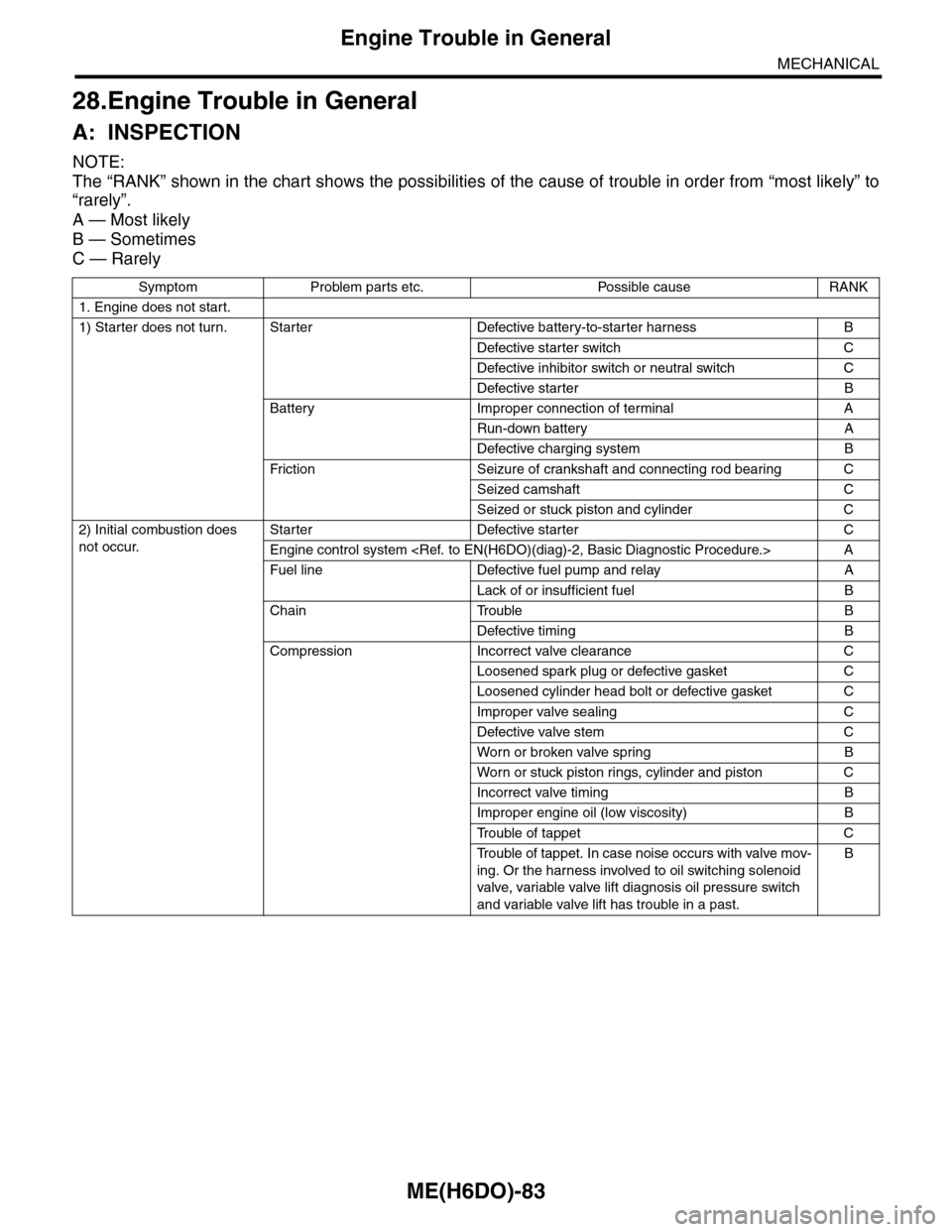
NOTE:
The “RANK” shown in the chart shows the possibilities of the cause of trouble in order from “most likely” to
“rarely”.
A — Most likely
B — Sometimes
C — Rarely
Symptom Problem parts etc. Possible cause RANK
1. Engine does not start.
1) Starter does not turn. Starter Defective battery-to-starter harness B
Defective starter switch C
Defective inhibitor switch or neutral switch C
Defective starter B
Battery Improper connection of terminal A
Run-down battery A
Defective charging system B
Fr iction Seizure of crankshaft and connecting rod bear ing C
Seized camshaft C
Seized or stuck piston and cylinder C
2) Initial combustion does
not occur.
Starter Defective starter C
Engine control system A
Fuel line Defective fuel pump and relay A
Lack of or insufficient fuel B
Chain Trouble B
Defective timing B
Compression Incorrect valve clearance C
Loosened spark plug or defective gasket C
Loosened cylinder head bolt or defective gasket C
Improper valve sealing C
Defective valve stem C
Wor n or broken valve spr ing B
Wor n or stuck piston r ings, cylinder and piston C
Incorrect valve timing B
Improper engine oil (low viscosity) B
Tr o u b l e o f t a p p e t C
Tr o u b l e o f t a p p e t . I n c a s e n o i s e o c c u r s w i t h v a l v e m o v -
ing. Or the harness involved to oil switching solenoid
valve, variable valve lift diagnosis oil pressure switch
and variable valve lift has trouble in a past.
B
Page 1960 of 2453

SC(H6DO)-2
General Description
STARTING/CHARGING SYSTEMS
1. General Description
A: SPECIFICATION
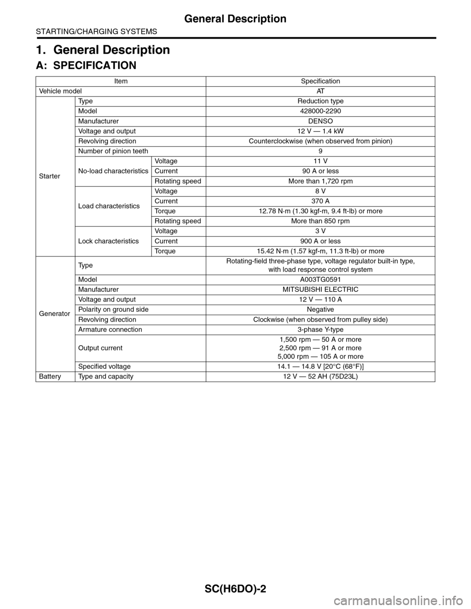
Item Specification
Ve h i c l e m o d e lAT
Starter
Ty p e R e d u c t i o n t y p e
Model 428000-2290
Manufacturer DENSO
Vo l t a g e a n d o u t p u t 1 2 V — 1 . 4 k W
Revolving direction Counterclockwise (when observed from pinion)
Number of pinion teeth 9
No-load characteristics
Vo l t a g e 1 1 V
Current 90 A or less
Rotating speed More than 1,720 rpm
Load characteristics
Vo l t a g e 8 V
Current 370 A
To r q u e 1 2 . 7 8 N · m ( 1 . 3 0 k g f - m , 9 . 4 f t - l b ) o r m o r e
Rotating speed More than 850 rpm
Lock characteristics
Vo l t a g e 3 V
Current 900 A or less
To r q u e 1 5 . 4 2 N · m ( 1 . 5 7 k g f - m , 1 1 . 3 f t - l b ) o r m o r e
Generator
Ty p eRotating-field three-phase type, voltage regulator built-in type,
with load response control system
Model A003TG0591
Manufacturer MITSUBISHI ELECTRIC
Vo l t a g e a n d o u t p u t 1 2 V — 1 1 0 A
Po la r i t y on gr ou n d s id e N e g at i ve
Revolving direction Clockwise (when observed from pulley side)
Armature connection 3-phase Y-type
Output current
1,500 rpm — 50 A or more
2,500 rpm — 91 A or more
5,000 rpm — 105 A or more
Specified voltage 14.1 — 14.8 V [20°C (68°F)]
Battery Type and capacity 12 V — 52 AH (75D23L)
Page 1961 of 2453
SC(H6DO)-3
General Description
STARTING/CHARGING SYSTEMS
B: COMPONENT
1. STARTER
(1) Front bracket (12) Wave washer (23) Space ring
(2) Front bearing (13) Internal gear (24) Snap ring
(3) Plunger (14) Washer (25) End frame cover
(4) Snap ring (15) Shaft (26) Plunger spring
(5) Stopper (16) Planetary gear (27) Magnet switch
(6) Overrunning clutch (17) Armature plate
(7) Snap ring (18) YokeTightening torque: N·m (kgf-m, ft-lb)
(8) Washer (19) ArmatureT1: 1.4 (0.14, 1.03)
(9) Lever (20) Brush holder ASSYT2: 6 (0.6, 4.4)
(10) Oilless bearing (21) End frameT3: 7.5 (0.8, 5.5)
(11) Shock absorber bearing (22) Rear bearingT4: 10 (1.0, 7.4)
SC-02108
T3
T1
T2
(1)
(2)
T4
(4)(21)
(22)
(23)
(24)
(25)(5)(6)
(7)
(8)
(15)
(14)(13)
(12)(11)
(10)(9)
(3)
(26)
(27)
(16)(17)
(18)
(19)
(20)
Page 1962 of 2453
SC(H6DO)-4
General Description
STARTING/CHARGING SYSTEMS
2. GENERATOR
(1) Pulley nut (7) Bearing (13) Terminals
(2) Pulley (8) Stator coil
(3) Front cover (9) IC regulator with brushTightening torque: N·m (kgf-m, ft-lb)
(4) Ball bearing (10) BrushT1: 3.9 (0.4, 2.9)
(5) Bearing retainer (11) RectifierT2: 4.6 (0.47, 3.4)
(6) Rotor (12) Rear coverT3: 103 (10.5, 76)
Page 1963 of 2453
SC(H6DO)-5
General Description
STARTING/CHARGING SYSTEMS
C: CAUTION
•Wear work clothing, including a cap, protective
goggles and protective shoes during operation.
•Remove contamination including dirt and corro-
sion before removal, installation or disassembly.
•Keep the disassembled parts in order and pro-
tect them from dust and dirt.
•Before removal, installation or disassembly, be
sure to clarify the failure. Avoid unnecessary re-
moval, installation, disassembly and replacement.
•Be careful not to burn yourself, because each
part on the vehicle is hot after running.
•Be sure to tighten fasteners including bolts and
nuts to the specified torque.
•Place shop jacks or rigid racks at the specified
points.
•Before disconnecting connectors of sensors or
units, be sure to disconnect the ground cable from
battery.
Page 1964 of 2453

SC(H6DO)-6
Starter
STARTING/CHARGING SYSTEMS
2. Starter
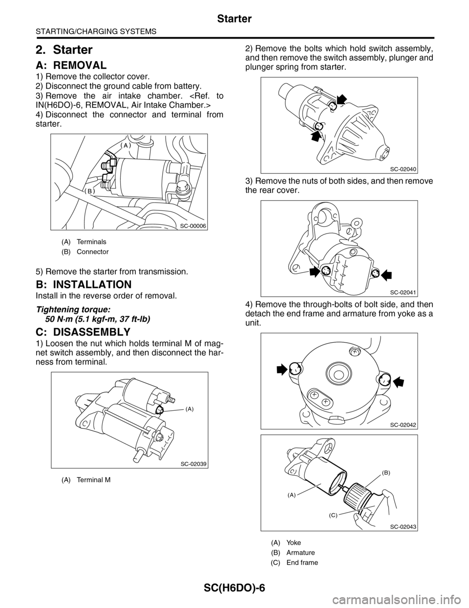
A: REMOVAL
1) Remove the collector cover.
2) Disconnect the ground cable from battery.
3) Remove the air intake chamber.
IN(H6DO)-6, REMOVAL, Air Intake Chamber.>
4) Disconnect the connector and terminal from
starter.
5) Remove the starter from transmission.
B: INSTALLATION
Install in the reverse order of removal.
Tightening torque:
50 N·m (5.1 kgf-m, 37 ft-lb)
C: DISASSEMBLY
1) Loosen the nut which holds terminal M of mag-
net switch assembly, and then disconnect the har-
ness from terminal.
2) Remove the bolts which hold switch assembly,
and then remove the switch assembly, plunger and
plunger spring from starter.
3) Remove the nuts of both sides, and then remove
the rear cover.
4) Remove the through-bolts of bolt side, and then
detach the end frame and armature from yoke as a
unit.
(A) Terminals
(B) Connector
(A) Terminal M
SC-00006
(A)
SC-02039
(A) Yoke
(B) Armature
(C) End frame
SC-02040
SC-02041
SC-02042
SC-02043
(A)
(C)
(B)
Page 1965 of 2453
SC(H6DO)-7
Starter
STARTING/CHARGING SYSTEMS
5) Remove the end frame cover.
6) Remove the snap ring.
7) Remove the space ring.
8) Remove the armature from end frame.
9) Remove the screws.
10) Remove the brush holder assembly from end
frame.
11) Remove the yoke from front bracket.
12) Remove the armature plate from the yoke.
13) Remove the rubber seal and planetary gear.
(A) End frame cover
(A) Snap ring
(B) Space ring
(A)
SC-02044
SC-02045
SC-02046
(A)
(B)
SC-02047
(A) Rubber seal
(B) Planetary gear
SC-02048
SC-02049
SC-02050
SC-02051
(A)
(B)