2009 SUBARU TRIBECA automatic
[x] Cancel search: automaticPage 2139 of 2453
5AT(diag)-22
SPORT Indicator Light Display
AUTOMATIC TRANSMISSION (DIAGNOSTICS)
11.SPORT Indicator Light Display
A: OPERATION
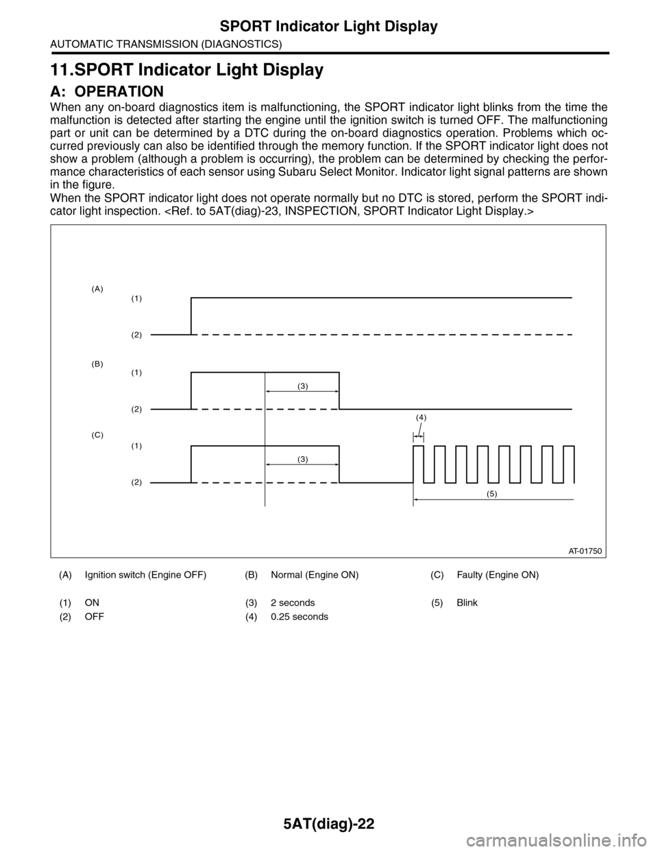
When any on-board diagnostics item is malfunctioning, the SPORT indicator light blinks from the time the
malfunction is detected after starting the engine until the ignition switch is turned OFF. The malfunctioning
part or unit can be determined by a DTC during the on-board diagnostics operation. Problems which oc-
curred previously can also be identified through the memory function. If the SPORT indicator light does not
show a problem (although a problem is occurring), the problem can be determined by checking the perfor-
mance characteristics of each sensor using Subaru Select Monitor. Indicator light signal patterns are shown
in the figure.
When the SPORT indicator light does not operate normally but no DTC is stored, perform the SPORT indi-
cator light inspection.
(A) Ignition switch (Engine OFF) (B) Normal (Engine ON) (C) Faulty (Engine ON)
(1) ON (3) 2 seconds (5) Blink
(2) OFF (4) 0.25 seconds
AT-01750
(4)
(3)
(1)
(2)
(1)
(2)
(1)
(2)
(3)
(5)
(A)
(B)
(C)
Page 2140 of 2453
5AT(diag)-23
SPORT Indicator Light Display
AUTOMATIC TRANSMISSION (DIAGNOSTICS)
B: INSPECTION
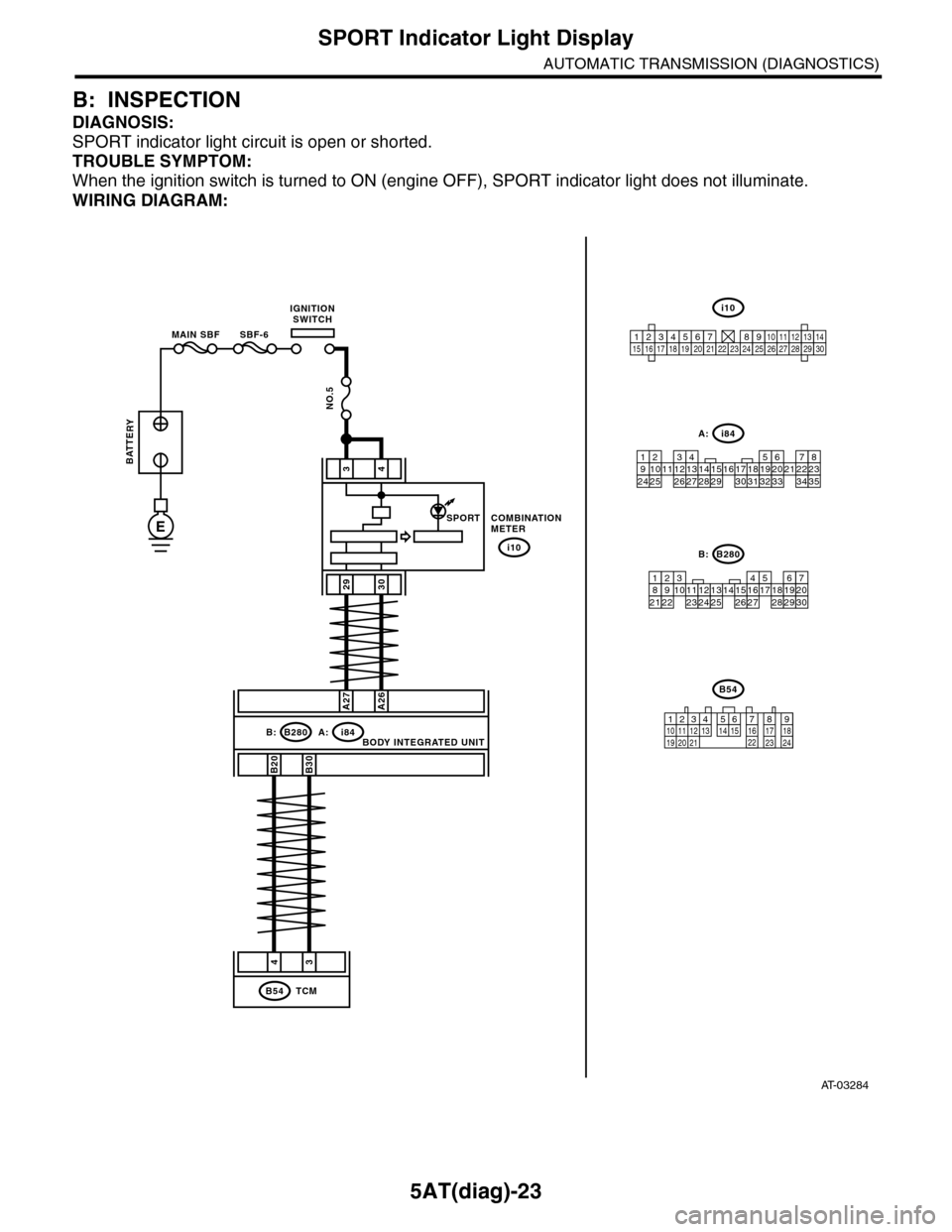
DIAGNOSIS:
SPORT indicator light circuit is open or shorted.
TROUBLE SYMPTOM:
When the ignition switch is turned to ON (engine OFF), SPORT indicator light does not illuminate.
WIRING DIAGRAM:
AT-03284
34
2930
COMBINATIONMETER
i10
i84A:B280B:
A27A26
B20B30
43
TCMB54
BODY INTEGRATED UNIT
SPORT
BATTERY
MAIN SBF SBF-6
IGNITIONSWITCH
NO.5
E
i84
8765432122232120191615141312111093435333217301831292827262524
A:
B280
87654321
2223212019161514131211109173018292827262524
B:
B54
12789563410 11 1219 20 2113 14 15 16 17 18222324
i10
123456789101112131415161718192021222324252627282930
Page 2141 of 2453
5AT(diag)-24
SPORT Indicator Light Display
AUTOMATIC TRANSMISSION (DIAGNOSTICS)
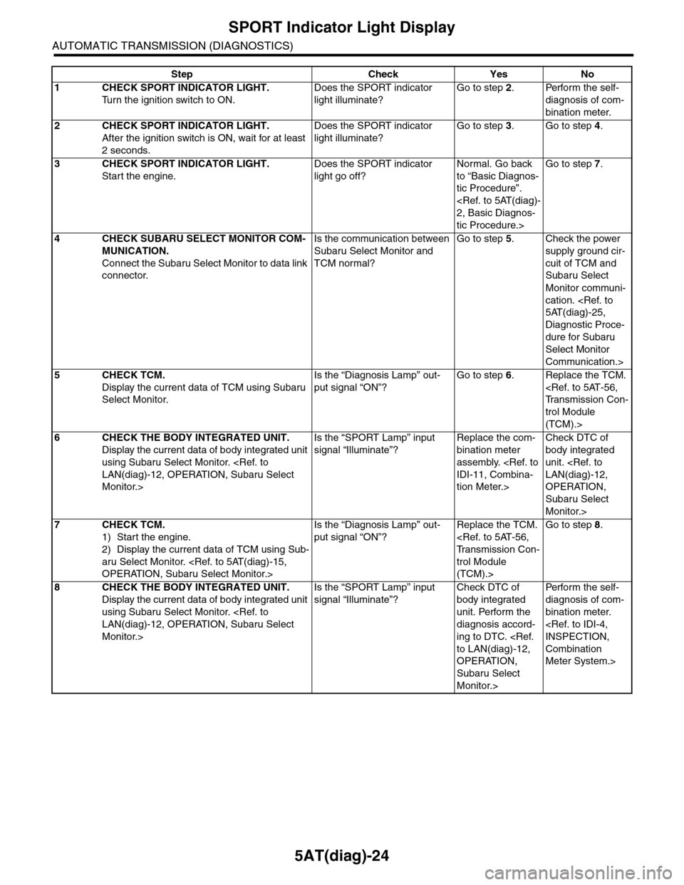
Step Check Yes No
1CHECK SPORT INDICATOR LIGHT.
Tu r n t h e i g n i t i o n s w i t c h t o O N .
Does the SPORT indicator
light illuminate?
Go to step 2.Perform the self-
diagnosis of com-
bination meter.
2CHECK SPORT INDICATOR LIGHT.
After the ignition switch is ON, wait for at least
2 seconds.
Does the SPORT indicator
light illuminate?
Go to step 3.Go to step 4.
3CHECK SPORT INDICATOR LIGHT.
Start the engine.
Does the SPORT indicator
light go off?
Normal. Go back
to “Basic Diagnos-
tic Procedure”.
tic Procedure.>
Go to step 7.
4CHECK SUBARU SELECT MONITOR COM-
MUNICATION.
Connect the Subaru Select Monitor to data link
connector.
Is the communication between
Subaru Select Monitor and
TCM normal?
Go to step 5.Check the power
supply ground cir-
cuit of TCM and
Subaru Select
Monitor communi-
cation.
Diagnostic Proce-
dure for Subaru
Select Monitor
Communication.>
5CHECK TCM.
Display the current data of TCM using Subaru
Select Monitor.
Is the “Diagnosis Lamp” out-
put signal “ON”?
Go to step 6.Replace the TCM.
trol Module
(TCM).>
6CHECK THE BODY INTEGRATED UNIT.
Display the current data of body integrated unit
using Subaru Select Monitor.
Monitor.>
Is the “SPORT Lamp” input
signal “Illuminate”?
Replace the com-
bination meter
assembly.
tion Meter.>
Check DTC of
body integrated
unit.
OPERATION,
Subaru Select
Monitor.>
7CHECK TCM.
1) Start the engine.
2) Display the current data of TCM using Sub-
aru Select Monitor.
Is the “Diagnosis Lamp” out-
put signal “ON”?
Replace the TCM.
trol Module
(TCM).>
Go to step 8.
8CHECK THE BODY INTEGRATED UNIT.
Display the current data of body integrated unit
using Subaru Select Monitor.
Monitor.>
Is the “SPORT Lamp” input
signal “Illuminate”?
Check DTC of
body integrated
unit. Perform the
diagnosis accord-
ing to DTC.
OPERATION,
Subaru Select
Monitor.>
Per fo r m th e se lf -
diagnosis of com-
bination meter.
Combination
Meter System.>
Page 2142 of 2453
5AT(diag)-25
Diagnostic Procedure for Subaru Select Monitor Communication
AUTOMATIC TRANSMISSION (DIAGNOSTICS)
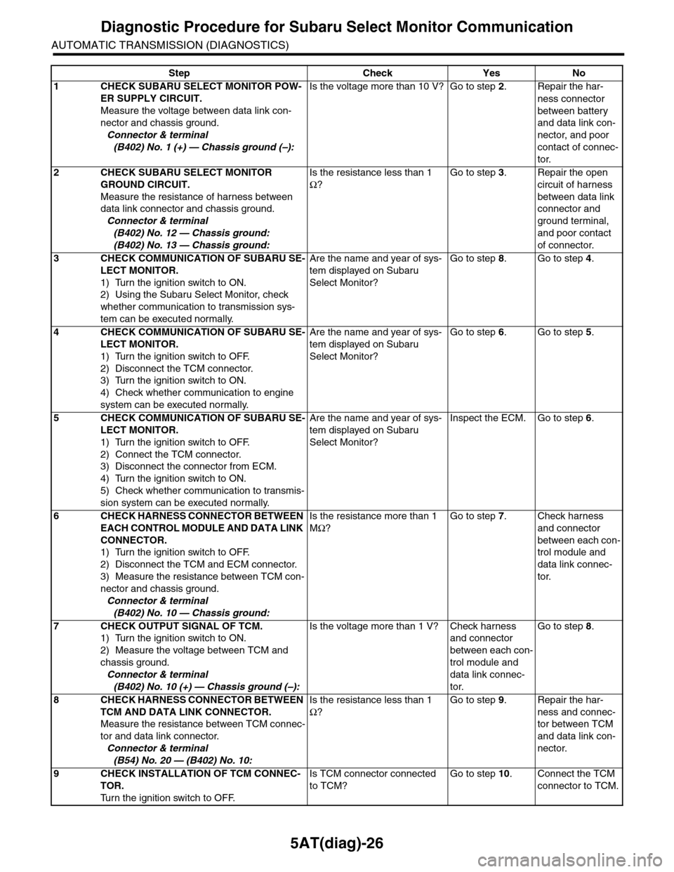
12.Diagnostic Procedure for Subaru Select Monitor Communication
A: COMMUNICATION FOR INITIALIZING IMPOSSIBLE
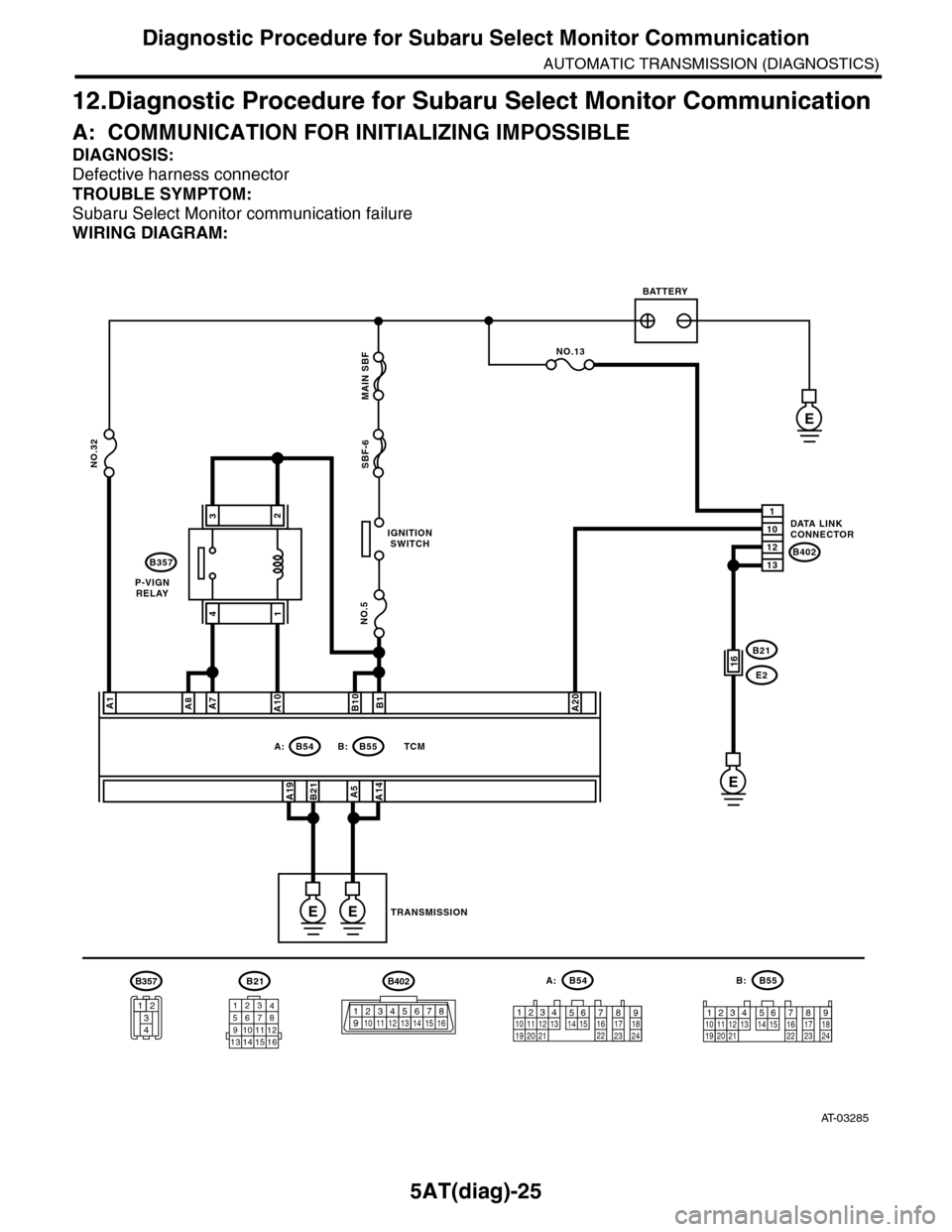
DIAGNOSIS:
Defective harness connector
TROUBLE SYMPTOM:
Subaru Select Monitor communication failure
WIRING DIAGRAM:
AT-03285
B21
12345678910111213 14 15 16
B54A:
12789563410 11 1219 20 2113 14 15 16 17 18222324
B55B:
12341011 121920 21135614 1578916 17 1822 23 24
IGNITIONSWITCH
P-VIGNRELAY
BATTERY
DATA LINKCONNECTOR
TRANSMISSION
B54A:B55
B357
B: TCM
B402
E
NO.5
NO.32SBF-6 MAIN SBF
A1
A19B21
B1B10A20
A5A14
1
12
10
13
NO.13
B21
E216
E
EE
A7A8A10
32
41
B402
123 8910413 14 15 165671112
B357
34
12
Page 2143 of 2453
5AT(diag)-26
Diagnostic Procedure for Subaru Select Monitor Communication
AUTOMATIC TRANSMISSION (DIAGNOSTICS)
Step Check Yes No
1CHECK SUBARU SELECT MONITOR POW-
ER SUPPLY CIRCUIT.
Measure the voltage between data link con-
nector and chassis ground.
Connector & terminal
(B402) No. 1 (+) — Chassis ground (–):
Is the voltage more than 10 V? Go to step 2.Repair the har-
ness connector
between battery
and data link con-
nector, and poor
contact of connec-
tor.
2CHECK SUBARU SELECT MONITOR
GROUND CIRCUIT.
Measure the resistance of harness between
data link connector and chassis ground.
Connector & terminal
(B402) No. 12 — Chassis ground:
(B402) No. 13 — Chassis ground:
Is the resistance less than 1
Ω?
Go to step 3.Repair the open
circuit of harness
between data link
connector and
ground terminal,
and poor contact
of connector.
3CHECK COMMUNICATION OF SUBARU SE-
LECT MONITOR.
1) Turn the ignition switch to ON.
2) Using the Subaru Select Monitor, check
whether communication to transmission sys-
tem can be executed normally.
Are the name and year of sys-
tem displayed on Subaru
Select Monitor?
Go to step 8.Go to step 4.
4CHECK COMMUNICATION OF SUBARU SE-
LECT MONITOR.
1) Turn the ignition switch to OFF.
2) Disconnect the TCM connector.
3) Turn the ignition switch to ON.
4) Check whether communication to engine
system can be executed normally.
Are the name and year of sys-
tem displayed on Subaru
Select Monitor?
Go to step 6.Go to step 5.
5CHECK COMMUNICATION OF SUBARU SE-
LECT MONITOR.
1) Turn the ignition switch to OFF.
2) Connect the TCM connector.
3) Disconnect the connector from ECM.
4) Turn the ignition switch to ON.
5) Check whether communication to transmis-
sion system can be executed normally.
Are the name and year of sys-
tem displayed on Subaru
Select Monitor?
Inspect the ECM. Go to step 6.
6CHECK HARNESS CONNECTOR BETWEEN
EACH CONTROL MODULE AND DATA LINK
CONNECTOR.
1) Turn the ignition switch to OFF.
2) Disconnect the TCM and ECM connector.
3) Measure the resistance between TCM con-
nector and chassis ground.
Connector & terminal
(B402) No. 10 — Chassis ground:
Is the resistance more than 1
MΩ?
Go to step 7.Check harness
and connector
between each con-
trol module and
data link connec-
tor.
7CHECK OUTPUT SIGNAL OF TCM.
1) Turn the ignition switch to ON.
2) Measure the voltage between TCM and
chassis ground.
Connector & terminal
(B402) No. 10 (+) — Chassis ground (–):
Is the voltage more than 1 V? Check harness
and connector
between each con-
trol module and
data link connec-
tor.
Go to step 8.
8CHECK HARNESS CONNECTOR BETWEEN
TCM AND DATA LINK CONNECTOR.
Measure the resistance between TCM connec-
tor and data link connector.
Connector & terminal
(B54) No. 20 — (B402) No. 10:
Is the resistance less than 1
Ω?
Go to step 9.Repair the har-
ness and connec-
tor between TCM
and data link con-
nector.
9CHECK INSTALLATION OF TCM CONNEC-
TOR.
Tu r n t h e i g n i t i o n s w i t c h t o O F F.
Is TCM connector connected
to TCM?
Go to step 10.Connect the TCM
connector to TCM.
Page 2144 of 2453
5AT(diag)-27
Diagnostic Procedure for Subaru Select Monitor Communication
AUTOMATIC TRANSMISSION (DIAGNOSTICS)
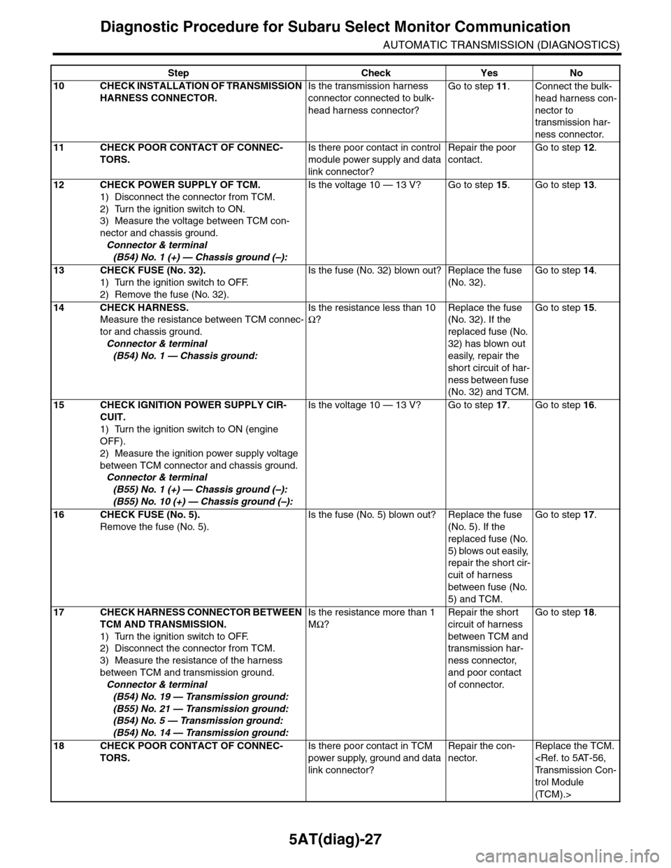
10 CHECK INSTALLATION OF TRANSMISSION
HARNESS CONNECTOR.
Is the transmission harness
connector connected to bulk-
head harness connector?
Go to step 11.Connect the bulk-
head harness con-
nector to
transmission har-
ness connector.
11 CHECK POOR CONTACT OF CONNEC-
TORS.
Is there poor contact in control
module power supply and data
link connector?
Repair the poor
contact.
Go to step 12.
12 CHECK POWER SUPPLY OF TCM.
1) Disconnect the connector from TCM.
2) Turn the ignition switch to ON.
3) Measure the voltage between TCM con-
nector and chassis ground.
Connector & terminal
(B54) No. 1 (+) — Chassis ground (–):
Is the voltage 10 — 13 V? Go to step 15.Go to step 13.
13 CHECK FUSE (No. 32).
1) Turn the ignition switch to OFF.
2) Remove the fuse (No. 32).
Is the fuse (No. 32) blown out? Replace the fuse
(No. 32).
Go to step 14.
14 CHECK HARNESS.
Measure the resistance between TCM connec-
tor and chassis ground.
Connector & terminal
(B54) No. 1 — Chassis ground:
Is the resistance less than 10
Ω?
Replace the fuse
(No. 32). If the
replaced fuse (No.
32) has blown out
easily, repair the
short circuit of har-
ness between fuse
(No. 32) and TCM.
Go to step 15.
15 CHECK IGNITION POWER SUPPLY CIR-
CUIT.
1) Turn the ignition switch to ON (engine
OFF).
2) Measure the ignition power supply voltage
between TCM connector and chassis ground.
Connector & terminal
(B55) No. 1 (+) — Chassis ground (–):
(B55) No. 10 (+) — Chassis ground (–):
Is the voltage 10 — 13 V? Go to step 17.Go to step 16.
16 CHECK FUSE (No. 5).
Remove the fuse (No. 5).
Is the fuse (No. 5) blown out? Replace the fuse
(No. 5). If the
replaced fuse (No.
5) blows out easily,
repair the short cir-
cuit of harness
between fuse (No.
5) and TCM.
Go to step 17.
17 CHECK HARNESS CONNECTOR BETWEEN
TCM AND TRANSMISSION.
1) Turn the ignition switch to OFF.
2) Disconnect the connector from TCM.
3) Measure the resistance of the harness
between TCM and transmission ground.
Connector & terminal
(B54) No. 19 — Transmission ground:
(B55) No. 21 — Transmission ground:
(B54) No. 5 — Transmission ground:
(B54) No. 14 — Transmission ground:
Is the resistance more than 1
MΩ?
Repair the short
circuit of harness
between TCM and
transmission har-
ness connector,
and poor contact
of connector.
Go to step 18.
18 CHECK POOR CONTACT OF CONNEC-
TORS.
Is there poor contact in TCM
power supply, ground and data
link connector?
Repair the con-
nector.
Replace the TCM.
trol Module
(TCM).>
Step Check Yes No
Page 2145 of 2453
5AT(diag)-28
List of Diagnostic Trouble Code (DTC)
AUTOMATIC TRANSMISSION (DIAGNOSTICS)
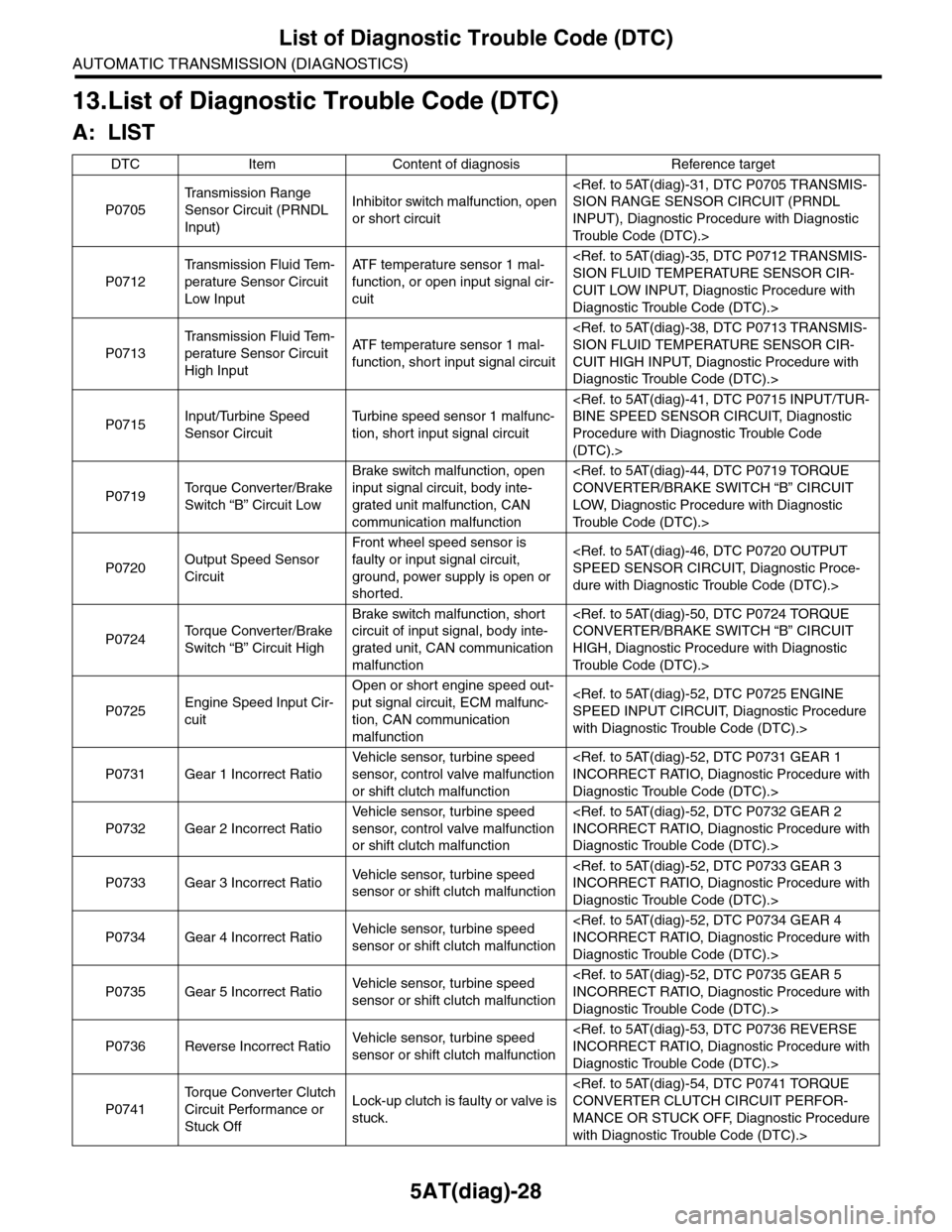
13.List of Diagnostic Trouble Code (DTC)
A: LIST
DTC Item Content of diagnosis Reference target
P0705
Tr a n s m i s s i o n R a n g e
Sensor Circuit (PRNDL
Input)
Inhibitor switch malfunction, open
or short circuit
INPUT), Diagnostic Procedure with Diagnostic
Tr o u b l e C o d e ( D T C ) . >
P0712
Tr a n s m i s s i o n F l u i d Te m -
perature Sensor Circuit
Low Input
AT F t e m p e r a t u r e s e n s o r 1 m a l -
function, or open input signal cir-
cuit
CUIT LOW INPUT, Diagnostic Procedure with
Diagnostic Trouble Code (DTC).>
P0713
Tr a n s m i s s i o n F l u i d Te m -
perature Sensor Circuit
High Input
AT F t e m p e r a t u r e s e n s o r 1 m a l -
function, short input signal circuit
CUIT HIGH INPUT, Diagnostic Procedure with
Diagnostic Trouble Code (DTC).>
P0715Input/Turbine Speed
Sensor Circuit
Tu r b i n e s p e e d s e n s o r 1 m a l f u n c -
tion, short input signal circuit
Procedure with Diagnostic Trouble Code
(DTC).>
P0719To r q u e C o n v e r t e r / B r a k e
Switch “B” Circuit Low
Brake switch malfunction, open
input signal circuit, body inte-
grated unit malfunction, CAN
communication malfunction
LOW, Diagnostic Procedure with Diagnostic
Tr o u b l e C o d e ( D T C ) . >
P0720Output Speed Sensor
Circuit
Front wheel speed sensor is
faulty or input signal circuit,
ground, power supply is open or
shorted.
dure with Diagnostic Trouble Code (DTC).>
P0724To r q u e C o n v e r t e r / B r a k e
Switch “B” Circuit High
Brake switch malfunction, short
circuit of input signal, body inte-
grated unit, CAN communication
malfunction
HIGH, Diagnostic Procedure with Diagnostic
Tr o u b l e C o d e ( D T C ) . >
P0725Engine Speed Input Cir-
cuit
Open or short engine speed out-
put signal circuit, ECM malfunc-
tion, CAN communication
malfunction
with Diagnostic Trouble Code (DTC).>
P0731 Gear 1 Incorrect Ratio
Ve h i c l e s e n s o r, t u r b i n e s p e e d
sensor, control valve malfunction
or shift clutch malfunction
Diagnostic Trouble Code (DTC).>
P0732 Gear 2 Incorrect Ratio
Ve h i c l e s e n s o r, t u r b i n e s p e e d
sensor, control valve malfunction
or shift clutch malfunction
Diagnostic Trouble Code (DTC).>
P0733 Gear 3 Incorrect RatioVe h i c l e s e n s o r, t u r b i n e s p e e d
sensor or shift clutch malfunction
Diagnostic Trouble Code (DTC).>
P0734 Gear 4 Incorrect RatioVe h i c l e s e n s o r, t u r b i n e s p e e d
sensor or shift clutch malfunction
Diagnostic Trouble Code (DTC).>
P0735 Gear 5 Incorrect RatioVe h i c l e s e n s o r, t u r b i n e s p e e d
sensor or shift clutch malfunction
Diagnostic Trouble Code (DTC).>
P0736 Reverse Incorrect RatioVe h i c l e s e n s o r, t u r b i n e s p e e d
sensor or shift clutch malfunction
Diagnostic Trouble Code (DTC).>
P0741
To r q u e C o n v e r t e r C l u t c h
Circuit Performance or
Stuck Off
Lock-up clutch is faulty or valve is
stuck.
MANCE OR STUCK OFF, Diagnostic Procedure
with Diagnostic Trouble Code (DTC).>
Page 2146 of 2453
5AT(diag)-29
List of Diagnostic Trouble Code (DTC)
AUTOMATIC TRANSMISSION (DIAGNOSTICS)
P0743To r q u e C o n v e r t e r C l u t c h
Circuit Electrical
L/U solenoid circuit malfunction
or L/U solenoid body malfunction
CAL, Diagnostic Procedure with Diagnostic Trou-
ble Code (DTC).>
P0748Pressure Control Sole-
noid “A” Electrical
Line pressure solenoid circuit
malfunction or line pressure sole-
noid body malfunction
nostic Procedure with Diagnostic Trouble Code
(DTC).>
P0751Shift Solenoid “A” Perfor-
mance or Stuck Off
Fr/B Solenoid Function Malfunc-
tion
OFF, Diagnostic Procedure with Diagnostic Trou-
ble Code (DTC).>
P0753Shift Solenoid “A” Elec-
trical
Fr/B solenoid circuit malfunction
or Fr/B solenoid body malfunction
cedure with Diagnostic Trouble Code (DTC).>
P0756Shift Solenoid “B” Perfor-
mance or Stuck Off
Shift Solenoid “B” Performance
malfunction
OFF, Diagnostic Procedure with Diagnostic Trou-
ble Code (DTC).>
P0758Shift Solenoid “B” Elec-
trical
I/C solenoid circuit malfunction or
I/C solenoid body malfunction
cedure with Diagnostic Trouble Code (DTC).>
P0761Shift Solenoid “C” Perfor-
mance or Stuck OffH&LR/C solenoid malfunction
OFF, Diagnostic Procedure with Diagnostic Trou-
ble Code (DTC).>
P0763Shift Solenoid “C” Elec-
trical
H&LR/C solenoid circuit malfunc-
tion or H&LR/C solenoid body
malfunction
cedure with Diagnostic Trouble Code (DTC).>
P0766Shift Solenoid “D” Perfor-
mance or Stuck OffD/C solenoid malfunction
OFF, Diagnostic Procedure with Diagnostic Trou-
ble Code (DTC).>
P0768Shift Solenoid “D” Elec-
trical
D/C solenoid circuit malfunction
or D/C solenoid body malfunction
Diagnostic Trouble Code (DTC).>
P0771Shift Solenoid “E” Perfor-
mance or Stuck OffLC/B solenoid malfunction
OFF, Diagnostic Procedure with Diagnostic Trou-
ble Code (DTC).>
P0773Shift Solenoid “E” Elec-
trical
•LC/B solenoid circuit malfunc-
tion or LC/B solenoid body mal-
function
•OFF malfunction of PVIGN
relay circuit or relay body
cedure with Diagnostic Trouble Code (DTC).>
P0801Reverse Inhibit Control
Circuit
•Shift lock solenoid is faulty or
output signal circuit is open or
shorted.
•Blown out of TCM+B fuse
dure with Diagnostic Trouble Code (DTC).>
P0817 Starter Disable Circuit
•PN signal output circuit is open
or shorted.
•ECM Source Voltage Is Abnor-
mal
•Blown out of TCM+B fuse
Diagnostic Trouble Code (DTC).>
P0882TCM Power Input Signal
Low
PVIGN relay output circuit is
open, shorted or relay malfunc-
tion
cedure with Diagnostic Trouble Code (DTC).>
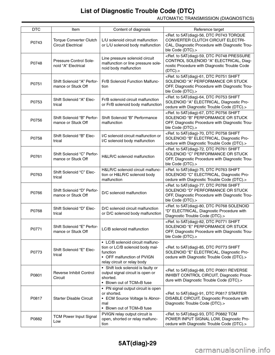
DTC Item Content of diagnosis Reference target