Page 2115 of 2453
5AT-99
AT Main Case
AUTOMATIC TRANSMISSION
F: ADJUSTMENT
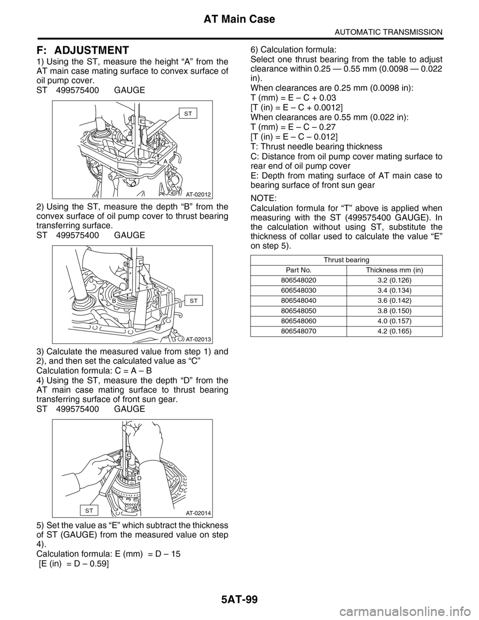
1) Using the ST, measure the height “A” from the
AT main case mating surface to convex surface of
oil pump cover.
ST 499575400 GAUGE
2) Using the ST, measure the depth “B” from the
convex surface of oil pump cover to thrust bearing
transferring surface.
ST 499575400 GAUGE
3) Calculate the measured value from step 1) and
2), and then set the calculated value as “C”
Calculation formula: C = A – B
4) Using the ST, measure the depth “D” from the
AT main case mating surface to thrust bearing
transferring surface of front sun gear.
ST 499575400 GAUGE
5) Set the value as “E” which subtract the thickness
of ST (GAUGE) from the measured value on step
4).
Calculation formula: E (mm) = D – 15
[E (in) = D – 0.59]
6) Calculation formula:
Select one thrust bearing from the table to adjust
clearance within 0.25 — 0.55 mm (0.0098 — 0.022
in).
When clearances are 0.25 mm (0.0098 in):
T (mm) = E – C + 0.03
[T (in) = E – C + 0.0012]
When clearances are 0.55 mm (0.022 in):
T (mm) = E – C – 0.27
[T (in) = E – C – 0.012]
T: Thrust needle bearing thickness
C: Distance from oil pump cover mating surface to
rear end of oil pump cover
E: Depth from mating surface of AT main case to
bearing surface of front sun gear
NOTE:
Calculation formula for “T” above is applied when
measuring with the ST (499575400 GAUGE). In
the calculation without using ST, substitute the
thickness of collar used to calculate the value “E”
on step 5).
AT-02012
ST
A
AT-02013
STB
AT-02014ST
D
Thrust bearing
Par t N o. Thickness mm (in)
806548020 3.2 (0.126)
606548030 3.4 (0.134)
806548040 3.6 (0.142)
806548050 3.8 (0.150)
806548060 4.0 (0.157)
806548070 4.2 (0.165)
Page 2116 of 2453
5AT-100
Transmission Control Device
AUTOMATIC TRANSMISSION
35.Transmission Control Device
A: REMOVAL
1) Remove the transmission assembly from vehicle
body.
Transmission Assembly.>
2) Pull out the torque converter assembly.
5AT-62, REMOVAL, Torque Converter Assembly.>
3) Lift-up the lever on the rear side of transmission
harness connector, and then disconnect it from the
stay.
4) Disconnect the air breather hose.
60, REMOVAL, Air Breather Hose.>
5) Wrap vinyl tape around the nipple attached to
the air breather hose.
6) Remove the pitching stopper bracket.
7) Remove the control valve body assembly.
to 5AT-53, REMOVAL, Control Valve Body.>
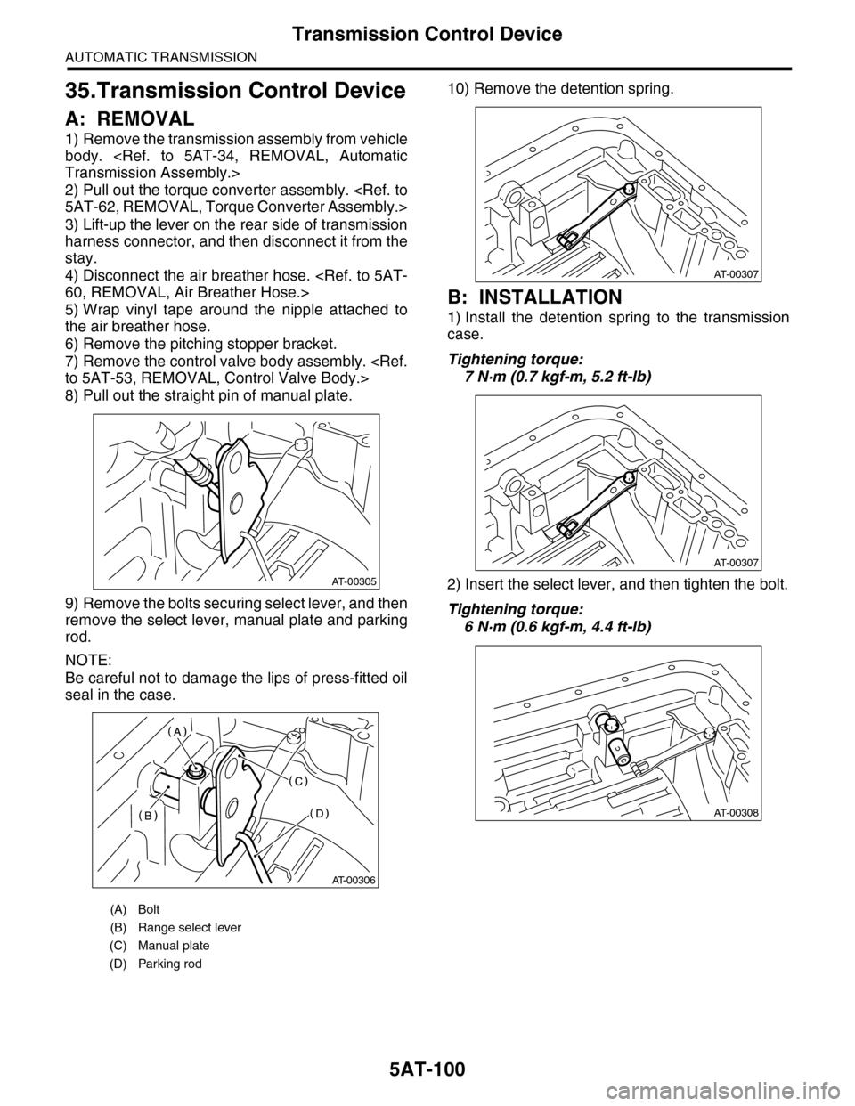
8) Pull out the straight pin of manual plate.
9) Remove the bolts securing select lever, and then
remove the select lever, manual plate and parking
rod.
NOTE:
Be careful not to damage the lips of press-fitted oil
seal in the case.
10) Remove the detention spring.
B: INSTALLATION
1) Install the detention spring to the transmission
case.
Tightening torque:
7 N·m (0.7 kgf-m, 5.2 ft-lb)
2) Insert the select lever, and then tighten the bolt.
Tightening torque:
6 N·m (0.6 kgf-m, 4.4 ft-lb)
(A) Bolt
(B) Range select lever
(C) Manual plate
(D) Parking rod
AT-00305
AT-00306
AT-00307
AT-00307
AT-00308
Page 2117 of 2453
5AT-101
Transmission Control Device
AUTOMATIC TRANSMISSION
3) Insert the manual plate and parking rod.
4) Insert the spring pin to the manual plate.
5) Install the oil pan and the control valve assem-
bly.
Valve Body.>
6) Install the pitching stopper bracket.
Tightening torque:
41 N·m (4.2 kgf-m, 30.4 ft-lb)
7) Insert the transmission connector to the stay.
8) Install the air breather hose.
STALLATION, Air Breather Hose.>
9) Install the torque converter assembly.
5AT-62, INSTALLATION, Torque Converter As-
sembly.>
10) Install the transmission assembly to the vehi-
cle.
Transmission Assembly.>
C: INSPECTION
Make sure the manual lever and detention spring
are not worn or otherwise damaged.
(A) Bolt
(B) Range select lever
(C) Manual plate
(D) Parking rod
AT-00306
AT-00305
Page 2118 of 2453
5AT-102
Transmission Control Device
AUTOMATIC TRANSMISSION
Page 2119 of 2453
5AT(diag)-2
Basic Diagnostic Procedure
AUTOMATIC TRANSMISSION (DIAGNOSTICS)
1. Basic Diagnostic Procedure
A: PROCEDURE
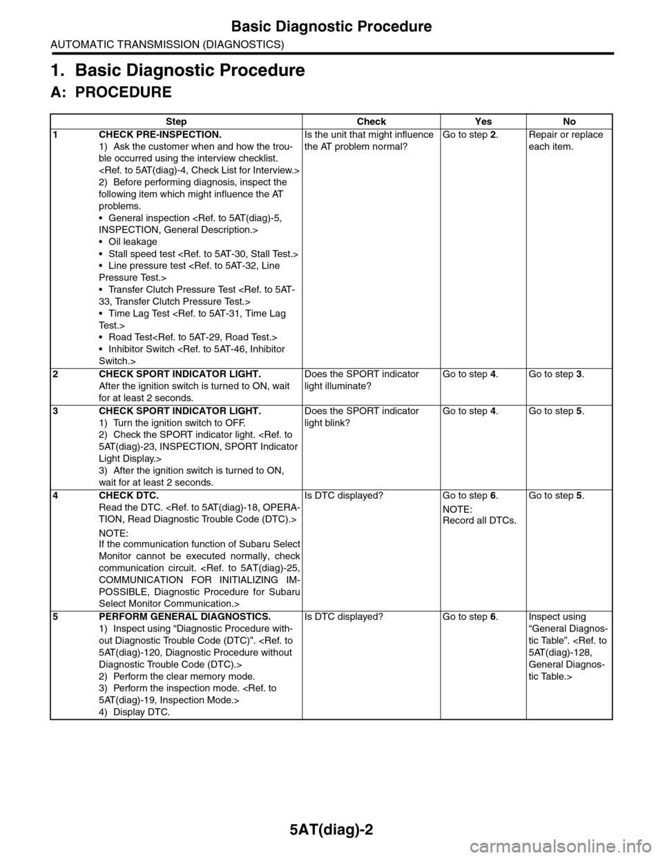
Step Check Yes No
1CHECK PRE-INSPECTION.
1) Ask the customer when and how the trou-
ble occurred using the interview checklist.
2) Before performing diagnosis, inspect the
following item which might influence the AT
problems.
•General inspection
INSPECTION, General Description.>
•Oil leakage
•Stall speed test
•Line pressure test
Pressure Test.>
•Transfer Clutch Pressure Test
33, Transfer Clutch Pressure Test.>
•Time Lag Test
Te s t . >
•Road Test
•Inhibitor Switch
Switch.>
Is the unit that might influence
the AT problem normal?
Go to step 2.Repair or replace
each item.
2CHECK SPORT INDICATOR LIGHT.
After the ignition switch is turned to ON, wait
for at least 2 seconds.
Does the SPORT indicator
light illuminate?
Go to step 4.Go to step 3.
3CHECK SPORT INDICATOR LIGHT.
1) Turn the ignition switch to OFF.
2) Check the SPORT indicator light.
5AT(diag)-23, INSPECTION, SPORT Indicator
Light Display.>
3) After the ignition switch is turned to ON,
wait for at least 2 seconds.
Does the SPORT indicator
light blink?
Go to step 4.Go to step 5.
4CHECK DTC.
Read the DTC.
TION, Read Diagnostic Trouble Code (DTC).>
NOTE:If the communication function of Subaru Select
Monitor cannot be executed normally, check
communication circuit.
COMMUNICATION FOR INITIALIZING IM-
POSSIBLE, Diagnostic Procedure for Subaru
Select Monitor Communication.>
Is DTC displayed? Go to step 6.
NOTE:
Record all DTCs.
Go to step 5.
5PERFORM GENERAL DIAGNOSTICS.
1) Inspect using “Diagnostic Procedure with-
out Diagnostic Trouble Code (DTC)”.
5AT(diag)-120, Diagnostic Procedure without
Diagnostic Trouble Code (DTC).>
2) Perform the clear memory mode.
3) Perform the inspection mode.
5AT(diag)-19, Inspection Mode.>
4) Display DTC.
Is DTC displayed? Go to step 6.Inspect using
“General Diagnos-
tic Table”.
5AT(diag)-128,
General Diagnos-
tic Table.>
Page 2120 of 2453
5AT(diag)-3
Basic Diagnostic Procedure
AUTOMATIC TRANSMISSION (DIAGNOSTICS)
6PERFORM THE DIAGNOSIS.
1) Inspect using the “Diagnostic Procedure
with Diagnostic Trouble Code (DTC)”.
5AT(diag)-31, Diagnostic Procedure with Diag-
nostic Trouble Code (DTC).>
NOTE:
For DTC table, refer to “List of Diagnostic Trou-
ble Code (DTC).”
Diagnostic Trouble Code (DTC).>
2) Repair the trouble cause.
3) Perform the clear memory mode.
4) Perform the inspection mode.
5AT(diag)-19, Inspection Mode.>
5) Display DTC.
Is DTC displayed? Inspect using the
“Diagnostic Proce-
dure with Diagnos-
tic Trouble Code
(DTC)”.
5AT(diag)-31,
Diagnostic Proce-
dure with Diagnos-
tic Trouble Code
(DTC).>
Inspect using
“General Diagnos-
tic Table”.
5AT(diag)-128,
General Diagnos-
tic Table.>
Step Check Yes No
Page 2121 of 2453
5AT(diag)-4
Check List for Interview
AUTOMATIC TRANSMISSION (DIAGNOSTICS)
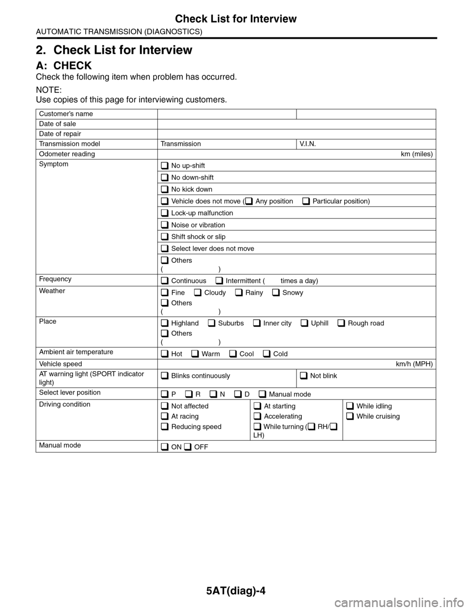
2. Check List for Interview
A: CHECK
Check the following item when problem has occurred.
NOTE:
Use copies of this page for interviewing customers.
Customer’s name
Date of sale
Date of repair
Tr a n s m i s s i o n m o d e l Tr a n s m i s s i o n V. I . N .
Odometer readingkm (miles)
Symptom No up-shift
No down-shift
No kick down
Vehicle does not move ( Any position Particular position)
Lock-up malfunction
Noise or vibration
Shift shock or slip
Select lever does not move
Others
()
Fr e qu e nc y Continuous Intermittent ( times a day)
Weather Fine Cloudy Rainy Snowy
Others
()
Place Highland Suburbs Inner city Uphill Rough road
Others
()
Ambient air temperature Hot Warm Cool Cold
Ve h i c l e s p e e dkm/h (MPH)
AT w a r n i n g l i g h t ( S P O R T i n d i c a t o r
light) Blinks continuously Not blink
Select lever position P R N D Manual mode
Driving condition Not affected
At racing
Reducing speed
At starting
Accelerating
W h i l e t u r n i n g ( R H /
LH)
While idling
While cruising
Manual mode ON OFF
Page 2122 of 2453
5AT(diag)-5
General Description
AUTOMATIC TRANSMISSION (DIAGNOSTICS)
3. General Description
A: CAUTION
•SRS AIRBAG SYSTEM
The airbag system wiring harness is routed near
the TCM.
CAUTION:
•All air bag system wiring harnesses and con-
nectors are colored yellow. Do not use an elec-
tric test equipment to check these circuits.
•Be careful not to damage the airbag system
wiring harness when performing diagnostics or
servicing the TCM.
•MEASUREMENT
When measuring the voltage and resistance of the
ECM, TCM or each sensor, use a tapered pin with
a diameter of less than 0.64 mm (0.025 in) in order
to avoid poor contact. Do not insert a pin of more
than 0.65 mm (0.026 in) diameter.
B: INSPECTION
1. BATTERY
Measure the battery voltage and specific gravity of
electrolyte.
Standard voltage: 12 V or more
Specific gravity: 1.260 or more
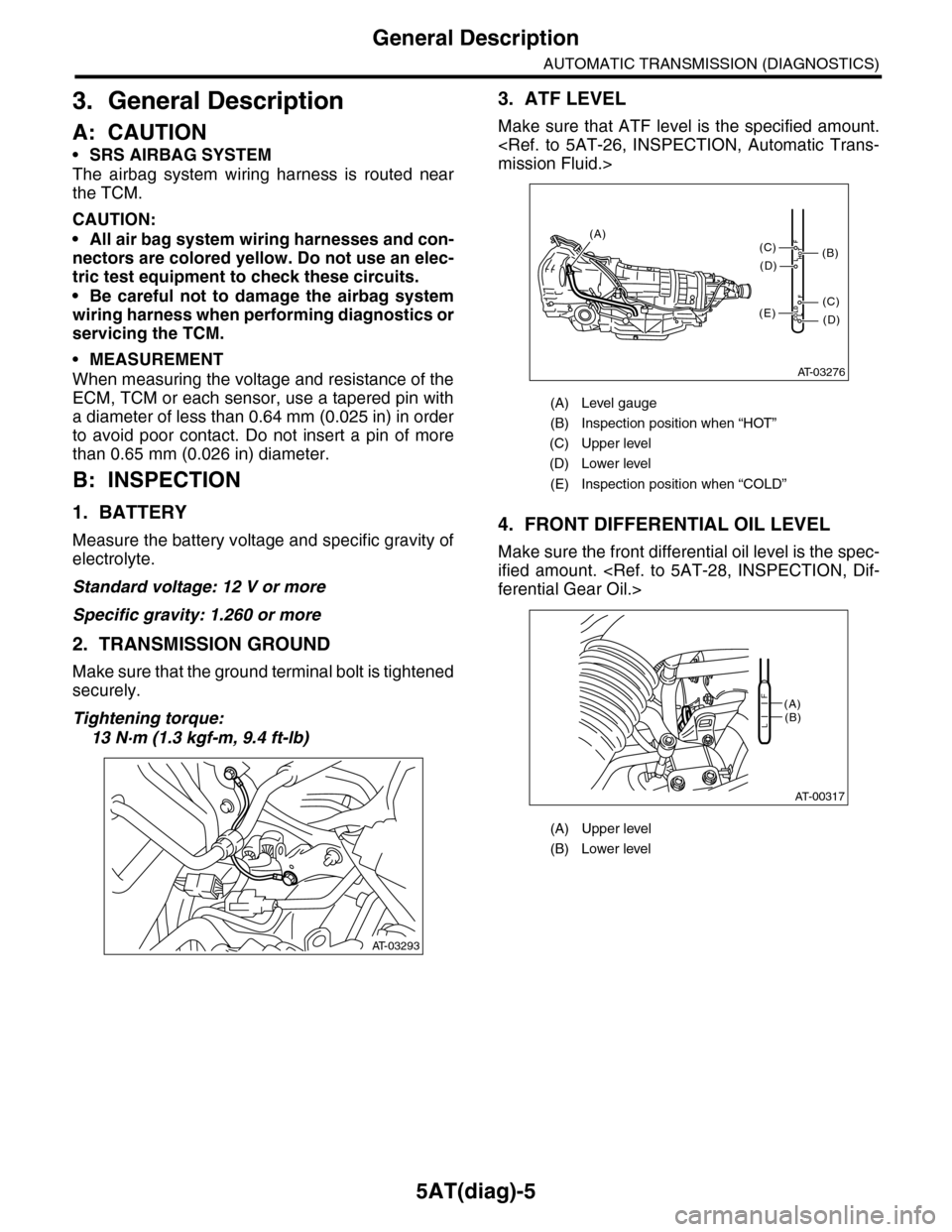
2. TRANSMISSION GROUND
Make sure that the ground terminal bolt is tightened
securely.
Tightening torque:
13 N·m (1.3 kgf-m, 9.4 ft-lb)
3. ATF LEVEL
Make sure that ATF level is the specified amount.
mission Fluid.>
4. FRONT DIFFERENTIAL OIL LEVEL
Make sure the front differential oil level is the spec-
ified amount.
ferential Gear Oil.>
AT-03293
(A) Level gauge
(B) Inspection position when “HOT”
(C) Upper level
(D) Lower level
(E) Inspection position when “COLD”
(A) Upper level
(B) Lower level
AT-03276
COLDLF
HOTLF
(C)
(D)
(C)
(D)
(E)
(B)
(A)
AT-00317
(A)(B)L
F