Page 1065 of 2453
VDC(diag)-73
Diagnostic Procedure with Diagnostic Trouble Code (DTC)
VEHICLE DYNAMICS CONTROL (VDC) (DIAGNOSTICS)
AO:DTC C0071 STEERING ANGLE SENSOR COMMUNICATION MALFUNCTION
DTC DETECTING CONDITION:
Defective steering angle sensor
TROUBLE SYMPTOM:
VDC does not operate.
WIRING DIAGRAM:
B310
1234
B231
12034
B231
E
241
3
B310 VDCCM & H/U
TWISTED PAIR LINE
STEERINGANGLESENSOR
1234
1516171819202122232425262728293031323334353637383940414245464344568910 11 12 13 147
VDC00376
MAIN SBF
NO.33
E
BATTERY
IGNITIONSWITCH
Page 1067 of 2453
VDC(diag)-75
Diagnostic Procedure with Diagnostic Trouble Code (DTC)
VEHICLE DYNAMICS CONTROL (VDC) (DIAGNOSTICS)
AP:DTC C0071 DEFECTIVE STEERING ANGLE SENSOR COMMUNICATION
DTC DETECTING CONDITION:
Signal does not come from steering angle sensor.
TROUBLE SYMPTOM:
VDC does not operate.
WIRING DIAGRAM:
B310
1234
B231
12034
B231
E
241
3
B310 VDCCM & H/U
TWISTED PAIR LINE
STEERINGANGLESENSOR
1234
1516171819202122232425262728293031323334353637383940414245464344568910 11 12 13 147
VDC00376
MAIN SBF
NO.33
E
BATTERY
IGNITIONSWITCH
Page 1072 of 2453
VDC(diag)-80
Diagnostic Procedure with Diagnostic Trouble Code (DTC)
VEHICLE DYNAMICS CONTROL (VDC) (DIAGNOSTICS)
AX:DTC C0072 YAW RATE SENSOR COMMUNICATION MALFUNCTION
DTC DETECTING CONDITION:
Yaw rate & G sensor malfunction
TROUBLE SYMPTOM:
•ABS does not operate.
•VDC does not operate.
WIRING DIAGRAM:
B310
12034
B359
E
3512
B310 VDCCM & H/U
TWISTED PAIR LINE
YAW RATE&G SENSOR
1234
1516171819202122232425262728293031323334353637383940414245464344568910 11 12 13 147
VDC00375
B359
12345
MAIN SBF
NO.33
E
BATTERY
IGNITIONSWITCH
Page 1074 of 2453
VDC(diag)-82
Diagnostic Procedure with Diagnostic Trouble Code (DTC)
VEHICLE DYNAMICS CONTROL (VDC) (DIAGNOSTICS)
BA:DTC C0074 PRESSURE SENSOR OPEN LINE
DTC DETECTING CONDITION:
Defective pressure sensor
TROUBLE SYMPTOM:
•ABS does not operate.
•VDC does not operate.
WIRING DIAGRAM:
MAIN SBF
SBF-6
NO.33
B310
E
E
431
VDCCM & H/U
BATTERY
GENERATOR
IGNITIONSWITCH
VDC00371
B310
1234
1516171819202122232425262728293031323334353637383940414245464344568910 11 12 13 147
Page 1077 of 2453
VDC(diag)-85
Diagnostic Procedure with Diagnostic Trouble Code (DTC)
VEHICLE DYNAMICS CONTROL (VDC) (DIAGNOSTICS)
BC:DTC C0074 PRESSURE SENSOR NOISE
DTC DETECTING CONDITION:
Defective pressure sensor
TROUBLE SYMPTOM:
•ABS does not operate.
•VDC does not operate.
WIRING DIAGRAM:
MAIN SBF
SBF-6
NO.33
B310
E
E
431
VDCCM & H/U
BATTERY
GENERATOR
IGNITIONSWITCH
VDC00371
B310
1234
1516171819202122232425262728293031323334353637383940414245464344568910 11 12 13 147
Page 1126 of 2453
CO(H6DO)-7
Radiator Fan System
COOLING
2. Radiator Fan System
A: WIRING DIAGRAM
CO-02209
RADIATOR FANCONTROL UNIT
132
B136
ECM
16
F109
F106
7
B360
2918
F106
123
B7
E
SBF-6MAIN SBF
NO.2
NO.26
B143B:
F36E:
E6
3127456
F36E:B143
123456712131415161718
B:
8191192010
EM
SUB FAN MOTORMAIN FAN MOTOR
THROUGH JOINTCONNECTOR
MAIN FANRELAY 1
MAIN FUSEBOX (M/B)
IGNITIONSWITCH
F17F11112
M
12
F111
F17
12
F109
3412 8910 1112 13 14 15 16 17 18 19 20 21 22 23 24567
B136
16101112131415252430
9871718192028212223293231
123456
2726333435
B360
12345678910111213141516
Page 1130 of 2453

CO(H6DO)-11
Engine Coolant
COOLING
11) Wait for one minute after the engine stops,
open the radiator cap. If the engine coolant level
drops, add engine coolant into radiator up to the fill-
er neck position.
12) Perform the procedures 10) and 11) again.
13) Attach the radiator cap and reservoir tank cap
properly.
14) Start the engine and operate the heater at max-
imum hot position and the blower speed setting to
“LO.”
15) Run the engine at 2,000 rpm or less until radia-
tor fan starts and stops.
NOTE:
•Be careful with the engine coolant temperature
gauge to prevent overheating.
•If the radiator hose becomes harden with the
pressure of engine coolant, air bleeding operation
seems to be almost completed.
16) Stop the engine and wait until the engine cool-
ant temperature lowers to 30°C (86°F).
17) Open the radiator cap. If the engine coolant lev-
el drops, add engine coolant into radiator up to the
filler neck position and reservoir tank to the “FULL”
level.
18) Attach the radiator cap and reservoir tank cap
properly.
19) Set the heater setting to maximum hot position
and the blower speed setting to “LO” and start the
engine. Perform racing at less than 3,000 rpm. If
the flowing sound is heard at this time, perform the
procedures from 15) again.
B: INSPECTION
1. RELATIONSHIP OF SUBARU COOLANT
CONCENTRATION AND FREEZING TEM-
PERATURE
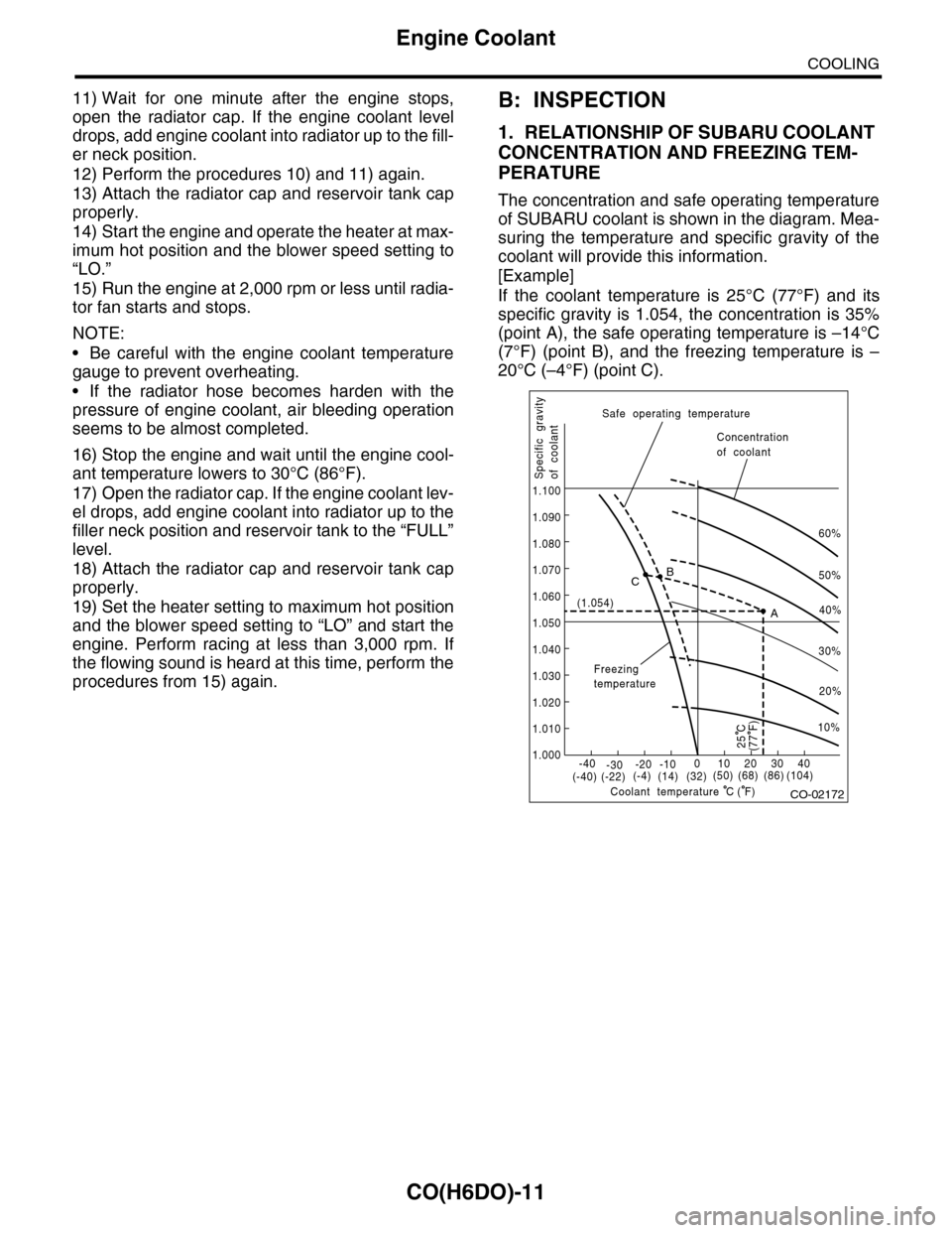
The concentration and safe operating temperature
of SUBARU coolant is shown in the diagram. Mea-
suring the temperature and specific gravity of the
coolant will provide this information.
[Example]
If the coolant temperature is 25°C (77°F) and its
specific gravity is 1.054, the concentration is 35%
(point A), the safe operating temperature is –14°C
(7°F) (point B), and the freezing temperature is –
20°C (–4°F) (point C).
CO-02172
60%
(1.054)
1.000
1.010
1.020
1.030
1.040
1.050
1.060
1.070
1.080
1.090
1.100
Safe operating temperature
Freezingtemperature
Concentrationof coolant
Specific gravityof coolant
Coolant temperature
B
A
C
-40(-40) (-22)(-4)(14)(32)(50) (68) (86)
( F)
(104)-30-20 -10010203040
(77 F)
50%
40%
30%
20%
25 C
10%
C
Page 1131 of 2453

CO(H6DO)-12
Engine Coolant
COOLING
2. PROCEDURE TO ADJUST THE CON-
CENTRATION OF THE COOLANT
To adjust the concentration of coolant according to
temperature, find the proper fluid concentration in
the above diagram and replace the necessary
amount of coolant with an undiluted solution of
SUBARU Genuine Coolant (concentration 50%).
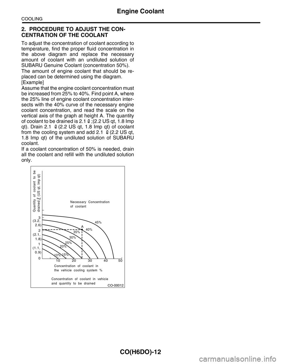
The amount of engine coolant that should be re-
placed can be determined using the diagram.
[Example]
Assume that the engine coolant concentration must
be increased from 25% to 40%. Find point A, where
the 25% line of engine coolant concentration inter-
sects with the 40% curve of the necessary engine
coolant concentration, and read the scale on the
vertical axis of the graph at height A. The quantity
of coolant to be drained is 2.12;(2.2 US qt, 1.8 Imp
qt). Drain 2.1 2(2.2 US qt, 1.8 Imp qt) of coolant
from the cooling system and add 2.1 2(2.2 US qt,
1.8 Imp qt) of the undiluted solution of SUBARU
coolant.
If a coolant concentration of 50% is needed, drain
all the coolant and refill with the undiluted solution
only.
CO-00012
100
1
2
3
(1.1, 0.9)
(2.1, 1.8)
(3.2, 2.6)
10%15%
25%20%
30%
35%40%
45%A
20 30 40 50
Concentration of coolant in vehicieand quantity to be drained
Quantity of coolant to bedrained (US qt, Imp qt)
Necessary Concentrationof coolant
Concentration of coolant inthe vehicie cooling system %