Page 1064 of 2453
VDC(diag)-72
Diagnostic Procedure with Diagnostic Trouble Code (DTC)
VEHICLE DYNAMICS CONTROL (VDC) (DIAGNOSTICS)
AN:DTC C0057 TRANSMISSION SYSTEM MALFUNCTION
DTC DETECTING CONDITION:
Transmission System Defect
TROUBLE SYMPTOM:
•ABS does not operate.
•VDC does not operate.
Step Check Yes No
1CHECK AT SYSTEM.
1) Start the engine.
2) Check the DTC in AT system.
Is DTC of AT system dis-
played?
Repair the AT sys-
tem.
Go to step 2.
2CHECK THE VDCCM&H/U.
1) Connect all the connectors.
2) Erase the memory.
3) Perform the inspection mode.
4) Read the DTC.
Is the same DTC displayed? Replace the
VDCCM&H/U.
Go to step 3.
3CHECK OTHER DTC DETECTION.Is any other DTC displayed? Perform the diag-
nosis according to
DTC.
Te m p o r a r y p o o r
contact occurs.
Page 1071 of 2453

VDC(diag)-79
Diagnostic Procedure with Diagnostic Trouble Code (DTC)
VEHICLE DYNAMICS CONTROL (VDC) (DIAGNOSTICS)
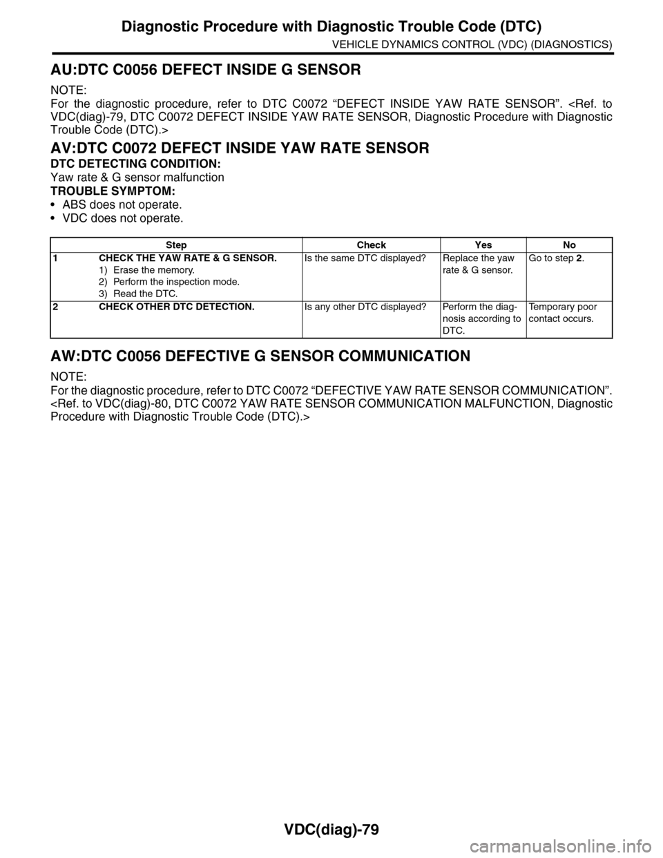
AU:DTC C0056 DEFECT INSIDE G SENSOR
NOTE:
For the diagnostic procedure, refer to DTC C0072 “DEFECT INSIDE YAW RATE SENSOR”.
VDC(diag)-79, DTC C0072 DEFECT INSIDE YAW RATE SENSOR, Diagnostic Procedure with Diagnostic
Trouble Code (DTC).>
AV:DTC C0072 DEFECT INSIDE YAW RATE SENSOR
DTC DETECTING CONDITION:
Yaw rate & G sensor malfunction
TROUBLE SYMPTOM:
•ABS does not operate.
•VDC does not operate.
AW:DTC C0056 DEFECTIVE G SENSOR COMMUNICATION
NOTE:
For the diagnostic procedure, refer to DTC C0072 “DEFECTIVE YAW RATE SENSOR COMMUNICATION”.
Procedure with Diagnostic Trouble Code (DTC).>
Step Check Yes No
1CHECK THE YAW RATE & G SENSOR.
1) Erase the memory.
2) Perform the inspection mode.
3) Read the DTC.
Is the same DTC displayed? Replace the yaw
rate & G sensor.
Go to step 2.
2CHECK OTHER DTC DETECTION.Is any other DTC displayed? Perform the diag-
nosis according to
DTC.
Te m p o r a r y p o o r
contact occurs.
Page 1072 of 2453
VDC(diag)-80
Diagnostic Procedure with Diagnostic Trouble Code (DTC)
VEHICLE DYNAMICS CONTROL (VDC) (DIAGNOSTICS)
AX:DTC C0072 YAW RATE SENSOR COMMUNICATION MALFUNCTION
DTC DETECTING CONDITION:
Yaw rate & G sensor malfunction
TROUBLE SYMPTOM:
•ABS does not operate.
•VDC does not operate.
WIRING DIAGRAM:
B310
12034
B359
E
3512
B310 VDCCM & H/U
TWISTED PAIR LINE
YAW RATE&G SENSOR
1234
1516171819202122232425262728293031323334353637383940414245464344568910 11 12 13 147
VDC00375
B359
12345
MAIN SBF
NO.33
E
BATTERY
IGNITIONSWITCH
Page 1074 of 2453
VDC(diag)-82
Diagnostic Procedure with Diagnostic Trouble Code (DTC)
VEHICLE DYNAMICS CONTROL (VDC) (DIAGNOSTICS)
BA:DTC C0074 PRESSURE SENSOR OPEN LINE
DTC DETECTING CONDITION:
Defective pressure sensor
TROUBLE SYMPTOM:
•ABS does not operate.
•VDC does not operate.
WIRING DIAGRAM:
MAIN SBF
SBF-6
NO.33
B310
E
E
431
VDCCM & H/U
BATTERY
GENERATOR
IGNITIONSWITCH
VDC00371
B310
1234
1516171819202122232425262728293031323334353637383940414245464344568910 11 12 13 147
Page 1076 of 2453

VDC(diag)-84
Diagnostic Procedure with Diagnostic Trouble Code (DTC)
VEHICLE DYNAMICS CONTROL (VDC) (DIAGNOSTICS)
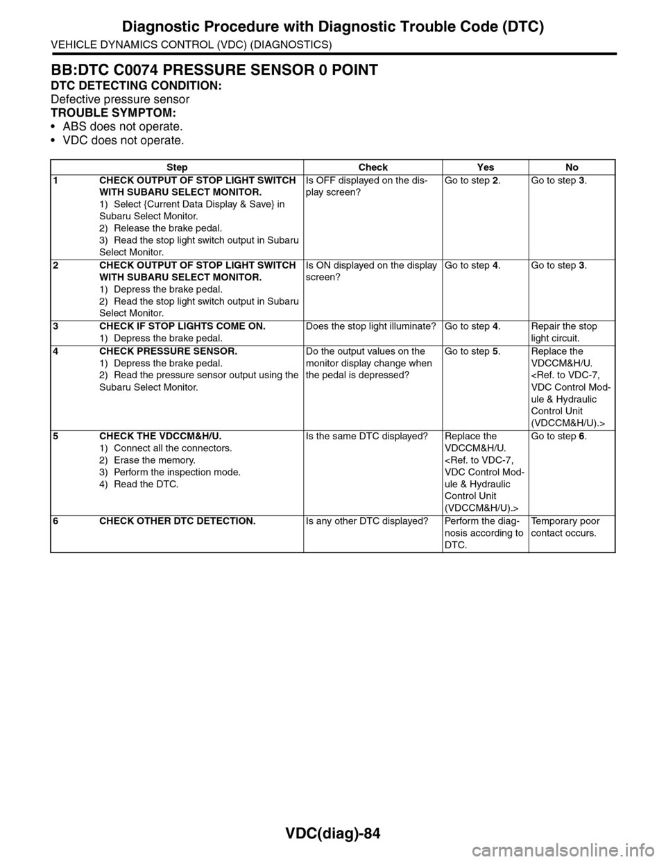
BB:DTC C0074 PRESSURE SENSOR 0 POINT
DTC DETECTING CONDITION:
Defective pressure sensor
TROUBLE SYMPTOM:
•ABS does not operate.
•VDC does not operate.
Step Check Yes No
1CHECK OUTPUT OF STOP LIGHT SWITCH
WITH SUBARU SELECT MONITOR.
1) Select {Current Data Display & Save} in
Subaru Select Monitor.
2) Release the brake pedal.
3) Read the stop light switch output in Subaru
Select Monitor.
Is OFF displayed on the dis-
play screen?
Go to step 2.Go to step 3.
2CHECK OUTPUT OF STOP LIGHT SWITCH
WITH SUBARU SELECT MONITOR.
1) Depress the brake pedal.
2) Read the stop light switch output in Subaru
Select Monitor.
Is ON displayed on the display
screen?
Go to step 4.Go to step 3.
3CHECK IF STOP LIGHTS COME ON.
1) Depress the brake pedal.
Does the stop light illuminate? Go to step 4.Repair the stop
light circuit.
4CHECK PRESSURE SENSOR.
1) Depress the brake pedal.
2) Read the pressure sensor output using the
Subaru Select Monitor.
Do the output values on the
monitor display change when
the pedal is depressed?
Go to step 5.Replace the
VDCCM&H/U.
VDC Control Mod-
ule & Hydraulic
Control Unit
(VDCCM&H/U).>
5CHECK THE VDCCM&H/U.
1) Connect all the connectors.
2) Erase the memory.
3) Perform the inspection mode.
4) Read the DTC.
Is the same DTC displayed? Replace the
VDCCM&H/U.
VDC Control Mod-
ule & Hydraulic
Control Unit
(VDCCM&H/U).>
Go to step 6.
6CHECK OTHER DTC DETECTION.Is any other DTC displayed? Perform the diag-
nosis according to
DTC.
Te m p o r a r y p o o r
contact occurs.
Page 1077 of 2453
VDC(diag)-85
Diagnostic Procedure with Diagnostic Trouble Code (DTC)
VEHICLE DYNAMICS CONTROL (VDC) (DIAGNOSTICS)
BC:DTC C0074 PRESSURE SENSOR NOISE
DTC DETECTING CONDITION:
Defective pressure sensor
TROUBLE SYMPTOM:
•ABS does not operate.
•VDC does not operate.
WIRING DIAGRAM:
MAIN SBF
SBF-6
NO.33
B310
E
E
431
VDCCM & H/U
BATTERY
GENERATOR
IGNITIONSWITCH
VDC00371
B310
1234
1516171819202122232425262728293031323334353637383940414245464344568910 11 12 13 147
Page 1079 of 2453

VDC(diag)-87
General Diagnostic Table
VEHICLE DYNAMICS CONTROL (VDC) (DIAGNOSTICS)
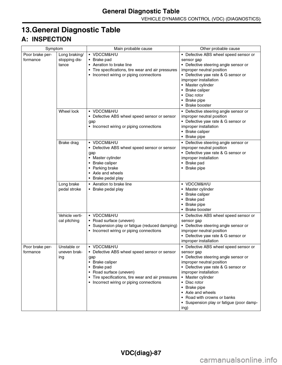
13.General Diagnostic Table
A: INSPECTION
Symptom Main probable cause Other probable cause
Po or b rake pe r -
for mance
Long braking/
stopping dis-
tance
•VDCCM&H/U
•Brake pad
•Aeration to brake line
•Tire specifications, tire wear and air pressures
•Incorrect wiring or piping connections
•Defective ABS wheel speed sensor or
sensor gap
•Defective steering angle sensor or
improper neutral position
•Defective yaw rate & G sensor or
improper installation
•Master cylinder
•Brake caliper
•Disc rotor
•Brake pipe
•Brake booster
Wheel lock • VDCCM&H/U
•Defective ABS wheel speed sensor or sensor
gap
•Incorrect wiring or piping connections
•Defective steering angle sensor or
improper neutral position
•Defective yaw rate & G sensor or
improper installation
•Brake caliper
•Brake pipe
Brake drag • VDCCM&H/U
•Defective ABS wheel speed sensor or sensor
gap
•Master cylinder
•Brake caliper
•Parking brake
•Axle and wheels
•Brake pedal play
•Defective steering angle sensor or
improper neutral position
•Defective yaw rate & G sensor or
improper installation
•Brake pad
•Brake pipe
Long brake
pedal stroke
•Aeration to brake line
•Brake pedal play
•VDCCM&H/U
•Master cylinder
•Brake caliper
•Brake pad
•Brake pipe
•Brake booster
Ve h i c l e v e r t i -
cal pitching
•VDCCM&H/U
•Road surface (uneven)
•Suspension play or fatigue (reduced damping)
•Incorrect wiring or piping connections
•Defective ABS wheel speed sensor or
sensor gap
•Defective steering angle sensor or
improper neutral position
•Defective yaw rate & G sensor or
improper installation
Po or b rake pe r -
for mance
Unstable or
uneven brak-
ing
•VDCCM&H/U
•Defective ABS wheel speed sensor or sensor
gap
•Brake caliper
•Brake pad
•Road surface (uneven)
•Tire specifications, tire wear and air pressures
•Incorrect wiring or piping connections
•Defective ABS wheel speed sensor or
sensor gap
•Defective steering angle sensor or
improper neutral position
•Defective yaw rate & G sensor or
improper installation
•Master cylinder
•Disc rotor
•Brake pipe
•Axle and wheels
•Road with crowns or banks
•Suspension play or fatigue (poor damp-
ing)
Page 1080 of 2453

VDC(diag)-88
General Diagnostic Table
VEHICLE DYNAMICS CONTROL (VDC) (DIAGNOSTICS)
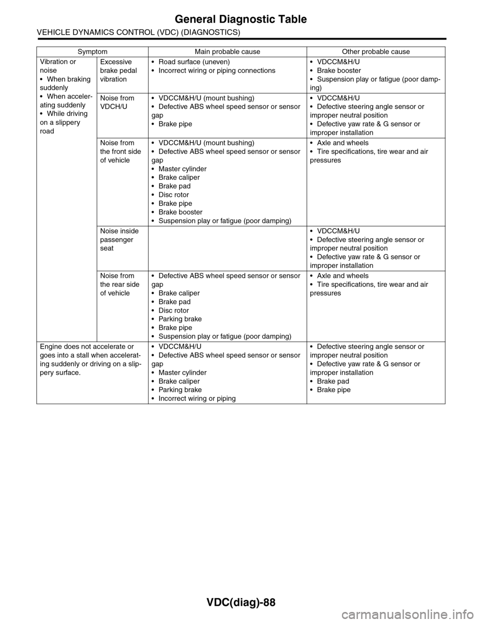
Vibration or
noise
•When braking
suddenly
•When acceler-
ating suddenly
•While driving
on a slippery
road
Excessive
brake pedal
vibration
•Road surface (uneven)
•Incorrect wiring or piping connections
•VDCCM&H/U
•Brake booster
•Suspension play or fatigue (poor damp-
ing)
Noise from
VDCH/U
•VDCCM&H/U (mount bushing)
•Defective ABS wheel speed sensor or sensor
gap
•Brake pipe
•VDCCM&H/U
•Defective steering angle sensor or
improper neutral position
•Defective yaw rate & G sensor or
improper installation
Noise from
the front side
of vehicle
•VDCCM&H/U (mount bushing)
•Defective ABS wheel speed sensor or sensor
gap
•Master cylinder
•Brake caliper
•Brake pad
•Disc rotor
•Brake pipe
•Brake booster
•Suspension play or fatigue (poor damping)
•Axle and wheels
•Tire specifications, tire wear and air
pressures
Noise inside
passenger
seat
•VDCCM&H/U
•Defective steering angle sensor or
improper neutral position
•Defective yaw rate & G sensor or
improper installation
Noise from
the rear side
of vehicle
•Defective ABS wheel speed sensor or sensor
gap
•Brake caliper
•Brake pad
•Disc rotor
•Parking brake
•Brake pipe
•Suspension play or fatigue (poor damping)
•Axle and wheels
•Tire specifications, tire wear and air
pressures
Engine does not accelerate or
goes into a stall when accelerat-
ing suddenly or driving on a slip-
pery surface.
•VDCCM&H/U
•Defective ABS wheel speed sensor or sensor
gap
•Master cylinder
•Brake caliper
•Parking brake
•Incorrect wiring or piping
•Defective steering angle sensor or
improper neutral position
•Defective yaw rate & G sensor or
improper installation
•Brake pad
•Brake pipe
Symptom Main probable cause Other probable cause