2009 SUBARU FORESTER turn signal
[x] Cancel search: turn signalPage 136 of 384
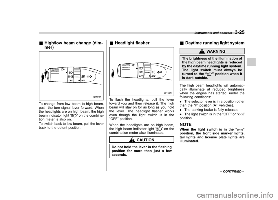
&High/low beam change (dim- mer)
To change from low beam to high beam,
push the turn signal lever forward. When
the headlights are on high beam, the high
beam indicator light “
”on the combina-
tion meter is also on.
To switch back to low beam, pull the lever
back to the detent position. &
Headlight flasher
To flash the headlights, pull the lever
toward you and then release it. The high
beam will stay on for as long as you hold
the lever. The headlight flasher works
even though the light switch is in the“OFF ”position.
When the headlights are on high beam,
the high beam indicator light “
”on the
combination meter also illuminates.
CAUTION
Do not hold the lever in the flashing
position for more than just a fewseconds. &
Daytime running light system
WARNING
The brightness of the illumination of
the high beam headlights is reduced
by the daytime running light system.
The light switch must always be
turned to the “
”position when it
is dark outside.
The high beam headlights will automati-
cally illuminate at reduced brightness
when the engine has started, under the
following conditions: . The selector lever is in a position other
than the “P ”position (AT vehicles).
. The parking brake is fully released.
. The light switch is in the “OFF ”or “
”
position.
NOTE
When the light switch is in the “
”
position, the front side marker lights,
tail lights and license plate lights areilluminated. Instruments and controls
3-25
– CONTINUED –
Page 137 of 384
3-26Instruments and controls
&Automatic headlight beam
leveler (vehicles with HID headlights)
The HID headlights generate more light
than conventional halogen headlights.
Therefore a driver of an oncoming vehicle
may experience too much glare when your
headlight beam height adjustment is high
due to the vehicle carrying heavy load.
The automatic headlight beam leveler
adjusts the headlight beam height auto-
matically and optimally according to the
load being carried by the vehicle. Turn signal lever
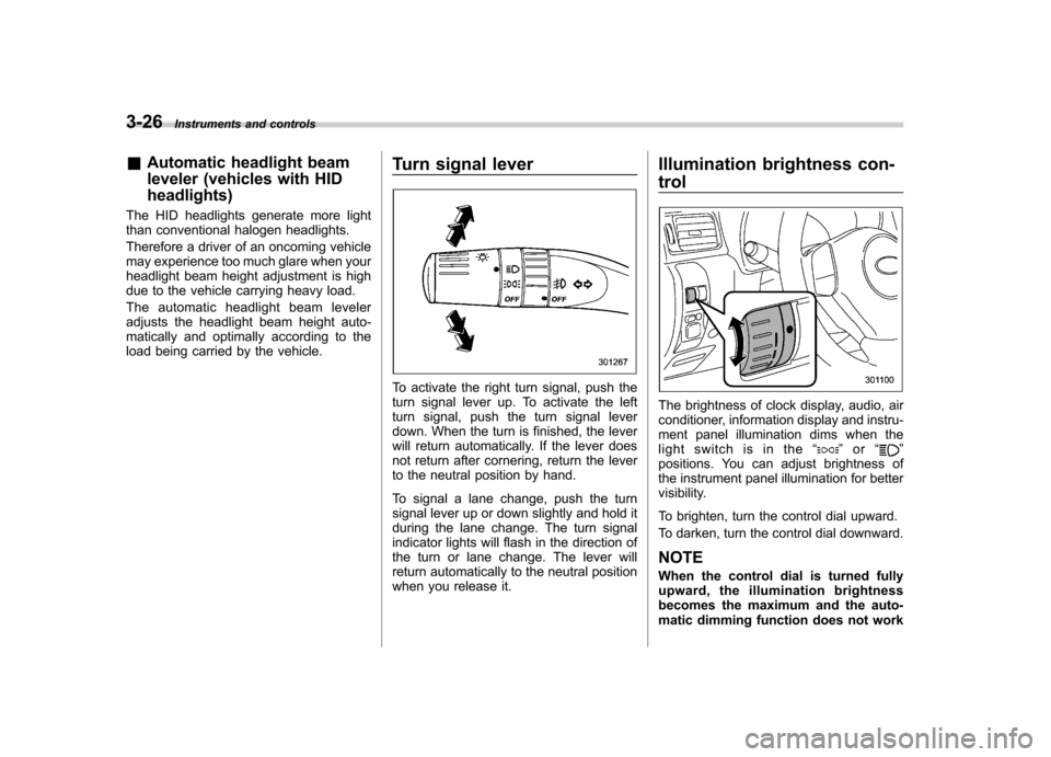
To activate the right turn signal, push the
turn signal lever up. To activate the left
turn signal, push the turn signal lever
down. When the turn is finished, the lever
will return automatically. If the lever does
not return after cornering, return the lever
to the neutral position by hand.
To signal a lane change, push the turn
signal lever up or down slightly and hold it
during the lane change. The turn signal
indicator lights will flash in the direction of
the turn or lane change. The lever will
return automatically to the neutral position
when you release it.Illumination brightness con- trol
The brightness of clock display, audio, air
conditioner, information display and instru-
ment panel illumination dims when the
light switch is in the
“
”or “”
positions. You can adjust brightness of
the instrument panel illumination for better
visibility.
To brighten, turn the control dial upward.
To darken, turn the control dial downward.
NOTE
When the control dial is turned fully
upward, the illumination brightness
becomes the maximum and the auto-
matic dimming function does not work
Page 138 of 384

at all.Front fog light switch (if equipped)
The front fog lights operate only when the
low beam headlights are illuminated.
However, the front fog lights turn off when
the headlights are switched to high beam.
To turn on the front fog lights, turn the front
fog light switch on the turn signal lever
upward to the“
”position. To turn off the
front fog lights, turn the switch back down
to the “OFF ”position.
The indicator light located on the combi-
nation meter will illuminate when the front
fog lights are on. Instruments and controls
3-27
Page 175 of 384
5-10Audio
FM/AM radio operation &FM/AM selection
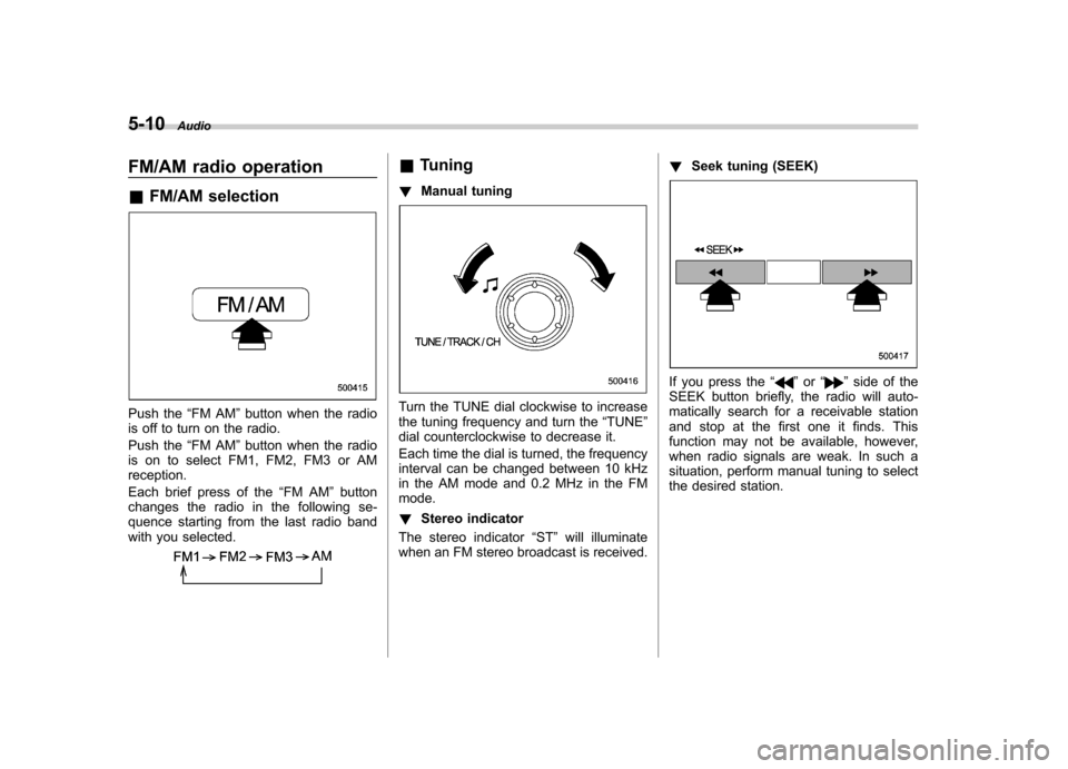
Push the “FM AM ”button when the radio
is off to turn on the radio.
Push the “FM AM ”button when the radio
is on to select FM1, FM2, FM3 or AM reception.
Each brief press of the “FM AM ”button
changes the radio in the following se-
quence starting from the last radio band
with you selected.
& Tuning
! Manual tuning
Turn the TUNE dial clockwise to increase
the tuning frequency and turn the “TUNE ”
dial counterclockwise to decrease it.
Each time the dial is turned, the frequency
interval can be changed between 10 kHz
in the AM mode and 0.2 MHz in the FMmode. ! Stereo indicator
The stereo indicator “ST ”will illuminate
when an FM stereo broadcast is received. !
Seek tuning (SEEK)
If you press the “”or “”side of the
SEEK button briefly, the radio will auto-
matically search for a receivable station
and stop at the first one it finds. This
function may not be available, however,
when radio signals are weak. In such a
situation, perform manual tuning to select
the desired station.
Page 220 of 384

transmitter within a few seconds immedi-
ately following remote engine start shut-down. &Pre-heating or pre-cooling
the interior of the vehicle
Before exiting the vehicle, set the tem-
perature controls to the desired setting
and operation. After the system starts the
vehicle, the heater or air-conditioning will
activate and heat or cool the interior to
your setting. & Service mode
In service mode, the remote start function
is temporarily disabled to prevent the
system from unexpectedly starting the
engine while being serviced. ! To engage the service mode
Turn the ignition switch to the “ON ”
position, depress and hold the brake
pedal, then press and release the “
”
button on the remote control transmitter
three times. The system will pause for 1
second and then flash the turn signal
lights and honk the horn three times
indicating that the system is in service
mode. When attempting to activate the
remote start system while in service
mode, the turn signal lights will flash and
the horn will honk two times and will not start. !
To disengage the service mode
Turn the ignition switch to the “ON ”
position, depress and hold the brake
pedal, then press and release the “
”
button on the remote control transmitter
three times. The system will pause for 1
second and flash the turn signal lights 1
time indicating that the system has exited
service mode. NOTE
When taking your vehicle in for service,
it is recommended that you inform the
service personnel that your vehicle is
equipped with a remote control startsystem. & Remote transmitter program-
ming and programmable fea-
ture option
New transmitters can be programmed to
the engine starter system in the event that
remote transmitters are lost, stolen or
damaged. The remote engine start system
also has one programmable feature that
can be adjusted for user preference.
The remote engine starter system can be
programmed to either make an audible
horn chirp upon remote start activation or
not. Remote transmitter programming and feature programming can be adjusted
using the following procedure.
1. Open the driver
’s door (the driver ’s
door must remain opened throughout the
entire process).
2. Insert the key into the vehicle ’s ignition
switch and turn to the “ON ”position.
3. Locate the small black programming
button behind the fuse box cover, on the
driver ’s side left under the dashboard
panel.
4. Press and hold the black programming
button for 10 to 15 seconds. The horn will
honk and the turn signal lights will flash
three times to indicate that the system has
entered programming mode. At this point
you can proceed to either step 5 or step 6.
5. To program a remote transmitter:
press and release the “
”button on each
transmitter. The horn will honk and the
turn signal lights will flash one time to
indicate a successful transmitter learn
each time the “
”button is pressed. You
can program up to eight transmitters.
6. To toggle the Horn Confirmation chirps
ON/OFF: press and release the brake to
toggle the feature. The horn will chirp and
the turn signal lights will flash one time to
indicate Confirmation Horn Chirps are“ OFF ”. The horn will honk and the turn
signal lights will flash 2 times to indicate
Confirmation Horn Chirps are “ON ”.
Starting and operating
7-11
– CONTINUED –
Page 227 of 384
7-18Starting and operating
& Selection of manual mode
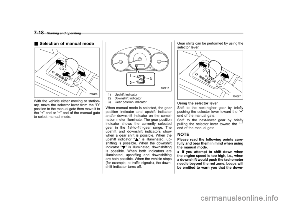
With the vehicle either moving or station-
ary, move the selector lever from the “D ”
position to the manual gate then move it tothe “+ ” end or “� ” end of the manual gate
to select manual mode.
1) Upshift indicator
2) Downshift indicator
3) Gear position indicator
When manual mode is selected, the gear
position indicator and upshift indicator
and/or downshift indicator on the combi-
nation meter illuminate. The gear position
indicator shows the currently selected
gear in the 1st-to-4th-gear range. The
upshift and downshift indicators show
when a gear shift is possible. When the
upshift indicator “
”is illuminated, up-
shifting is possible. When the downshift indicator “
”is illuminated, downshifting
is possible. When both indicators are
illuminated, upshifting and downshifting
are both possible. When the vehicle stops
(for example, at traffic signals), the down-
shift indicator turns off. Gear shifts can be performed by using the
selector lever.
Using the selector lever
Shift to the next-higher gear by briefly
pushing the selector lever toward the
“+ ”
end of the manual gate.
Shift to the next-lower gear by briefly
pulling the selector lever toward the “� ”
end of the manual gate. NOTE
Please read the following points care-
fully and bear them in mind when using
the manual mode. . If you attempt to shift down when
the engine speed is too high, i.e., when
a downshift would push the tachometer
needle beyond the red zone, beeps will
be emitted to warn you that the down-
Page 240 of 384

are now above the severe low
pressure threshold, the low tire
pressure warning light should turn
off a few minutes later.
If this light still illuminates while
driving after adjusting the tire pres-
sure, a tire may have significant
damage and a fast leak that causes
the tire to lose air rapidly. If you have
a flat tire, replace it with a spare tire
as soon as possible.
When a spare tire is mounted or a
wheel rim is replaced without the
original pressure sensor/transmitter
being transferred, the low tire pres-
sure warning light will illuminate
steadily after blinking for approxi-
mately 1 minute. This indicates the
TPMS is unable to monitor all four
road wheels. Contact your SUBARU
dealer as soon as possible for tire
and sensor replacement and/or sys-
tem resetting.
Do not inject any tire liquid or
aerosol tire sealant into the tires,
as this may cause a malfunction of
the tire pressure sensors. If the light
illuminates steadily after blinking for
approximately 1 minute, promptly
contact a SUBARU dealer to have
the system inspected.CAUTION
Do not place metal film or any metal
parts in the cargo room/trunk. This
may cause poor reception of the
signals from the tire pressure sen-
sors, and the tire pressure monitor-
ing system will not function prop-
erly.
NOTE
This device complies with Part 15 of
the FCC Rules and with RSS-210 of
Industry Canada. Operation is subject
to the following two conditions: (1) This
device may not cause harmful inter-
ference, and (2) this device must
accept any interference received, in-
cluding interference that may cause
undesired operation.
Changes or modifications not ex-
pressly approved by the party respon-
sible for compliance could void theuser ’s authority to operate the equip-
ment. Parking your vehicle &
Parking brake
To set the parking brake, press the brake
pedal firmly and hold it down until the
parking brake lever is fully pulled up.
To release the parking brake, pull the lever
up slightly, press the release button, then
lower the lever while keeping the button pressed.
When the parking brake is set while the
engine is running, the parking brake
warning light illuminates. After starting
the vehicle, be sure that the warning light
has gone out before the vehicle is driven.
Refer to the “Warning and indicator lights ”
section in chapter 3. Starting and operating
7-31
– CONTINUED –
Page 262 of 384
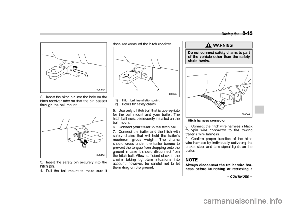
2. Insert the hitch pin into the hole on the
hitch receiver tube so that the pin passes
through the ball mount.
3. Insert the safety pin securely into the
hitch pin.
4. Pull the ball mount to make sure itdoes not come off the hitch receiver.
1) Hitch ball installation point
2) Hooks for safety chains
5. Use only a hitch ball that is appropriate
for the ball mount and your trailer. The
hitch ball must be securely installed on the
ball mount.
6. Connect your trailer to the hitch ball.
7. Connect the trailer and the hitch with
safety chains that will hold the trailer ’s
maximum gross weight. The chains
should cross under the trailer tongue to
prevent the tongue from dropping onto the
ground in case it should disconnect from
the hitch ball. Allow sufficient slack in the
chains taking tight-turn situations into
account; however, be careful not to let
them drag on the ground.
WARNING
Do not connect safety chains to part
of the vehicle other than the safety
chain hooks.
Hitch harness connector
8. Connect the hitch wire harness ’s black
four-pin wire connector to the towing trailer ’s wire harness
9. Confirm proper function of the hitch
wire harness by individually activating the
brake, stop, and turn signal lights on the
trailer.
NOTE
Always disconnect the trailer wire har-
ness before launching or retrieving a Driving tips
8-15
– CONTINUED –