2009 SUBARU FORESTER instrument panel
[x] Cancel search: instrument panelPage 4 of 384

Warranties &Warranties for U.S.A.
All SUBARU vehicles distributed by
Subaru of America, Inc. and sold at retail
by an authorized SUBARU dealer in the
United States come with the followingwarranties: . SUBARU Limited Warranty
. Emission Control Systems Warranty
. Emissions Performance Warranty
All warranty information, including details
of coverage and exclusions, is in the“ Warranty and Maintenance Booklet ”.
Please read these warranties carefully.
& Warranties for Canada
All SUBARU vehicles distributed by
Subaru Canada, Inc. and sold at retail by
an authorized SUBARU dealer in Canada
come with the following warranties: . SUBARU Limited Warranty
. Anti-Corrosion Warranty
. Emission Control Warranty
All warranty information, including details
of coverage and exclusions, is in the“ Warranty and Service Booklet ”. Please
read these warranties carefully. &
Vehicle with HID headlights
CAUTION
High Intensity Discharge (HID) head-
lights contain mercury. For that
reason, it is necessary to remove
HID headlights before vehicle dis-
posal. Once removed, please reuse,
recycle or dispose of the HID head-
lights as hazardous waste.
& Vehicle without HID head- lights
CAUTION
This vehicle does not contain mer-
cury devices or parts. How to use this Owner
’s
Manual & Using your Owner ’s Manual
Before you operate your vehicle, carefully
read this manual. To protect yourself and
extend the service life of your vehicle,
follow the instructions in this manual.
Failure to observe these instructions may
result in serious injury and damage to yourvehicle.
This manual is composed of fourteen
chapters. Each chapter begins with a brief
table of contents, so you can usually tell at
a glance if that chapter contains the
information you want.
Chapter 1: Seat, seatbelt and SRS airbags
This chapter informs you how to use the
seat and seatbelt and contains precau-
tions for the SRS airbags.
Chapter 2: Keys and doors
This chapter informs you how to operate
the keys, locks and windows.
Chapter 3: Instruments and controls
This chapter informs you about the opera-
tion of instrument panel indicators and
how to use the instruments and otherswitches. 1
– CONTINUED –
Page 6 of 384

Vehicle symbols
There are some of the symbols you may
see on your vehicle.Mark Name
WARNING
CAUTION
Power door lock and unlock
Passengers ’windows lock
and unlock
Fuel
Front fog lights
Hazard warning flasher
Engine hood Mark Name
Seat heater
Child restraint top tether an- chorages
Child restraint lower an- chorages
Horn
Windshield wiper deicer
Wiper intermittent
Windshield wiper and washer
Windshield wiper mist (for
single wipe)
Rear window wiper
Rear window washer
LightsMark Name
Tail lights, license plate light
and instrument panel illumi-nation
Headlights
Turn signal
Illumination brightness
Fan speed
Instrument panel outlets
Instrument panel outlets and
foot outlets
Foot outlets
Windshield defroster and foot outlets
Windshield defroster
Rear window defogger/Out-
side mirror defogger3
– CONTINUED –
Page 17 of 384

14 &Instrument panel
1) Door locks (page 2-4)
2) Outside mirror switch (page 3-35)
3) Illumination brightness control
(page 3-26)
4) Light control lever (page 3-24)
5) Combination meter (page 3-5)
6) Wiper control lever (page 3-28)
7) Hazard warning flasher switch (page 3-5)
8) Audio (page 5-1)
9) Shift lever (MT) (page 7-13)/ Selector lever (AT) (page 7-15)
10) Climate control (page 4-1)
11) Cruise control (page 7-34)
12) Horn (page 3-38)
13) SRS airbag (page 1-34)
14) Tilt/telescopic steering (page 3-36/ page 3-37)
15) Audio control buttons (page 5-26)
16) Fuse box (page 11-44)
17) Vehicle Dynamics Control OFF switch (page 7-29)
18) Hood lock release knob (page 11-5)
19) Power windows (page 2-19)
Page 69 of 384

1-44Seat, seatbelt and SRS airbags
. Ensure that there are no articles,
books, shoes, or other objects trapped
under the seat, at the rear of the seat, or
on the side of the seat. . Ensure that the backward-forward po-
sition and seatback of front passenger ’s
seat are locked into place securely by
moving the seat back and forth. . Next, turn the ignition switch to the
“ ON ”position and wait 6 seconds to allow
the system to complete self-checking.
Following the system check, both indica-
tors turn off for 2 seconds. Now, the ON
indicator should illuminate while the OFF
indicator remains off.
If the OFF indicator still remains illumi-
nated while the ON indicator remains off,
ask the occupant to move to the rear seat
and immediately contact your SUBARU
dealer for an inspection. ! Effect vehicle modifications made
for persons with disabilities may
have on SUBARU advanced frontal
airbag system operation (U.S. only)
Changing or moving any parts of the front
seats, rear seat, seatbelts, front bumper,
front side frame, radiator panel, instrument
panel, combination meter, steering wheel,
steering column, tire, suspension or floor
panel can affect the operation of the
SUBARU advanced airbag system. If you have any questions, you may contact
the following SUBARU distributors:
Subaru of America, Inc.
Customer Dealer Services Department
P.O. Box 6000
Cherry Hill, NJ 08034-6000
1-800-SUBARU3 (1-800-782-2783)
Servco Subaru Inc., dba Subaru Hawaii
2850 Pukoloa Street, Suite 202, Honolulu,
HI 96819 808-839-2273
’s Corporation dba Prestige Automo-
bile
491, East Marine Drive, Route 1 Dededo, Guam 671-633-2698
Trebol Motors
P.O. Box 11204, San Juan, Puerto Rico 00910 787-793-2828
There are currently no SUBARU distribu-
tors in any other U.S. territories. If you are
in such an area, please contact the SUBARU distributor or dealer from which
you bought your vehicle.
Page 77 of 384

1-52Seat, seatbelt and SRS airbags
A hands-free microphone or
other accessory in such a loca-
tion could be propelled through
the cabin with great force by the
curtain airbag, or it could prevent
correct deployment of the curtain
airbag. In either case, the result
could be serious injuries.
. Never hang or place coat hangers
or other hard or pointed objects
near the side windows. If such
items are present when the SRS
curtain airbags deploy, they
could be thrown through the
passenger compartment and
cause serious injuries. They
could also prevent proper opera-
tion of the SRS curtain airbags.WARNING
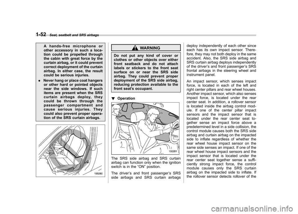
Do not put any kind of cover or
clothes or other objects over either
front seatback and do not attach
labels or stickers to the front seat
surface on or near the SRS side
airbag. They could prevent proper
deployment of the SRS side airbag,
reducing protection available to the
front seat ’s occupant.
! Operation
The SRS side airbag and SRS curtain
airbag can function only when the ignition
switch is in the “ON ”position.
The driver ’s and front passenger ’s SRS
side airbags and SRS curtain airbags deploy independently of each other since
each has its own impact sensor. There-
fore, they may not both deploy in the same
accident. Also, the SRS side airbag and
SRS curtain airbag deploys independently
of the driver
’s and front passenger ’s SRS
frontal airbags in the steering wheel and
instrument panel.
An impact sensor, which senses impact
force, is located in each of the left and
right center pillars and rear wheel houses.
Another impact sensor, which also senses
impact force, is located under the rear
center seat. In addition, a rollover sensor
is located inside the airbag control mod-
ule. If one of the center pillar impact
sensors and the impact sensor that is
located under the rear center seat to-
gether sense an impact force above a
predetermined level in a side collision, the
control module causes both the SRS side
airbag and curtain airbag on the impacted
side to inflate regardless of whether the
rear wheel house impact sensor on the
same side senses an impact. If one of the
rear wheel house impact sensors and the
impact sensor that is located under the
rear center seat together sense a suffi-
ciently strong impact force, the control
module causes only the SRS curtain
airbag on the impacted side to inflate. If
the rollover sensor detects rollover of the
Page 116 of 384

contains an immobilizer transponder. .The key is near or touching another
transmitter. & Key reminder chime
The reminder chime sounds when the driver ’s door opens and the key is in the
“ LOCK ”or “Acc ”position. The chime stops
when the ignition switch is turned to the“ ON ”position or the key is removed from
the ignition switch.
& Ignition switch light
For easy access to the ignition switch in
the dark, the ignition switch light illumi-
nates when driver ’s door is opened. The
light remains on for 20 seconds and turns
off after driver ’s door is closed. The light
turns off immediately if the key is turned tothe “ON ”position. Hazard warning flasher
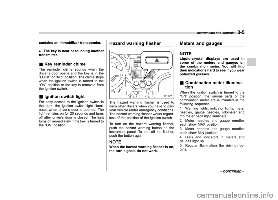
The hazard warning flasher is used to
warn other drivers when you have to park
your vehicle under emergency conditions.
The hazard warning flasher works regard-
less of the position of the ignition switch.
To turn on the hazard warning flasher,
push the hazard warning button on the
instrument panel. To turn off the flasher,
push the button again. NOTE
When the hazard warning flasher is on,
the turn signals do not work. Meters and gauges NOTE
Liquid-crystal displays are used in
some of the meters and gauges on
the combination meter. You will find
their indications hard to see if you wear
polarized glasses. &
Combination meter illumina- tion
When the ignition switch is turned to the “ ON ”position, the various parts of the
combination meter are illuminated in the
following sequence:
1. Warning lights, indicator lights, meter
needles, gauge needles, odometer and
trip meter back light illuminate.
2. Meter needles and gauge needles
each show MAX position.
3. Meter needles and gauge needles
each show MIN position.
4. Dials and indicators in meters and
gauges light up.
5. Regular illumination (for driving) be- gins. Instruments and controls
3-5
– CONTINUED –
Page 135 of 384

3-24Instruments and controls
Light control switch
The light control switch only operates
when the ignition key is inserted into the
ignition switch.
Regardless of the position of the light
control switch, the illuminated lights are
turned off when the ignition key is
removed from the ignition switch. NOTE .Even if the ignition key is removed
from the ignition switch, the lights can
be illuminated by operating the light
control switch position from “OFF ”to
“
” and/or “”.
. If the driver ’s door is opened while
the lights are illuminated and the igni-
tion key is removed from the ignition
switch, the chirp sound informs the
driver that the lights are illuminated.
CAUTION
. Use of any lights for a long period
of time while the engine is not
running can cause the battery todischarge.
. Before leaving the vehicle, make
sure that the light control switch
is turned to the “OFF ”position. If
the vehicle is left unattended for a long time with the light control
switch set to a position otherthan
“OFF ”, the battery may be
discharged. &
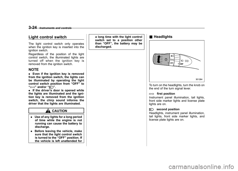
Headlights
To turn on the headlights, turn the knob on
the end of the turn signal lever.
first position
Instrument panel illumination, tail lights,
front side marker lights and license plate
lights are on.
second position
Headlights, instrument panel illumination,
tail lights, front side marker lights, and
license plate lights are on.
Page 137 of 384

3-26Instruments and controls
&Automatic headlight beam
leveler (vehicles with HID headlights)
The HID headlights generate more light
than conventional halogen headlights.
Therefore a driver of an oncoming vehicle
may experience too much glare when your
headlight beam height adjustment is high
due to the vehicle carrying heavy load.
The automatic headlight beam leveler
adjusts the headlight beam height auto-
matically and optimally according to the
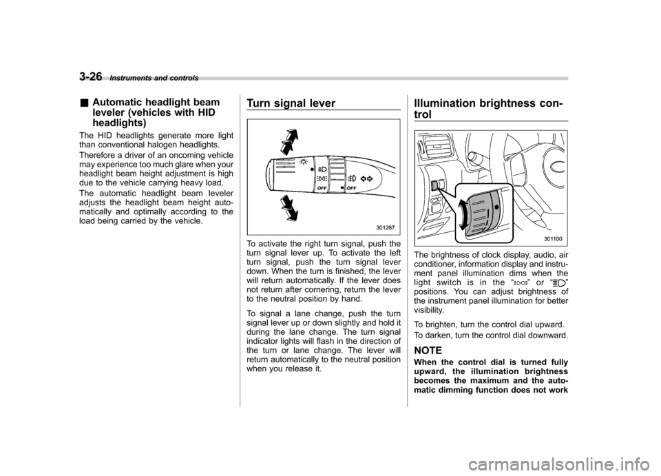
load being carried by the vehicle. Turn signal lever
To activate the right turn signal, push the
turn signal lever up. To activate the left
turn signal, push the turn signal lever
down. When the turn is finished, the lever
will return automatically. If the lever does
not return after cornering, return the lever
to the neutral position by hand.
To signal a lane change, push the turn
signal lever up or down slightly and hold it
during the lane change. The turn signal
indicator lights will flash in the direction of
the turn or lane change. The lever will
return automatically to the neutral position
when you release it.Illumination brightness con- trol
The brightness of clock display, audio, air
conditioner, information display and instru-
ment panel illumination dims when the
light switch is in the
“
”or “”
positions. You can adjust brightness of
the instrument panel illumination for better
visibility.
To brighten, turn the control dial upward.
To darken, turn the control dial downward.
NOTE
When the control dial is turned fully
upward, the illumination brightness
becomes the maximum and the auto-
matic dimming function does not work