2009 SUBARU FORESTER glove box
[x] Cancel search: glove boxPage 16 of 384

1) Center console (page 6-5)
2) Cup holder (page 6-7)
3) Front power supply socket (page 6-9)
4) Glove box (page 6-5)13
– CONTINUED –
Page 63 of 384

1-38Seat, seatbelt and SRS airbags
&SUBARU advanced frontal
airbag system
Your vehicle is equipped with a SUBARU
advanced frontal airbag system that com-
plies with the new advanced frontal airbag
requirements in the amended Federal
Motor Vehicle Safety Standard (FMVSS)
No. 208.
The SUBARU advanced frontal airbag
system automatically determines the de-
ployment force of the driver ’s SRS frontal
airbag at the time of deployment as well as
whether or not to activate the frontpassenger ’s SRS frontal airbag and, if
activated, the deployment force of the
SRS frontal airbag at the time of deploy-ment.
Your vehicle has warning labels on the driver ’s and front passenger ’s sun visors
beginning with the phrase “EVEN WITH
ADVANCED AIR BAGS ”and a tag
attached to the glove box lid beginning
with the phrase “Even with Advanced Air
Bags ”. Make sure that you carefully read
the instructions on the warning labels and tag.
Always wear your seatbelt. The SUBARU
advanced frontal airbag system is a
supplemental restraint system and must
be used in combination with a seatbelt. All
occupants should wear a seatbelt or be
seated in an appropriate child restraint system.
The driver
’s SRS frontal airbag is stowed
in the center portion of the steering wheel.
The front passenger ’s SRS frontal airbag
is stowed near the top of the dashboard
under an “SRS AIRBAG ”mark.
In a moderate to severe frontal collision,
the driver ’s and front passenger ’s SRS
frontal airbags deploy and supplement the
seatbelts by reducing the impact on thedriver ’s and front passenger ’s head and
chest.
WARNING
NEVER INSTALL A REARWARD FA-
CING CHILD SEAT IN THE FRONT
SEAT. DOING SO RISKS SERIOUS
INJURY OR DEATH TO THE CHILD BY PLACING THE CHILD
’S HEAD
TOO CLOSE TO THE SRS AIRBAG.
WARNING
Never allow a child to stand up, or to
kneel on the front passenger ’s seat.
The SRS airbag deploys with con-
siderable force and can injure or
even kill the child.
Page 89 of 384
2-2Keys and doors
Keys
1) Master key (black)
2) Submaster key (black)
3) Valet key (gray)
4) Key number plate
5) Security ID plate
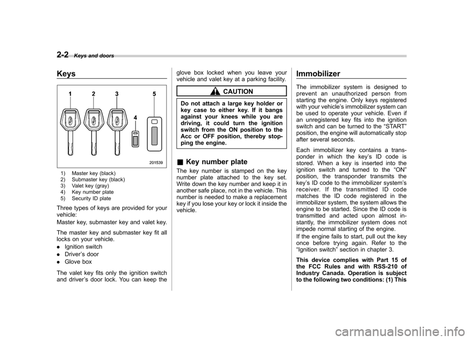
Three types of keys are provided for your vehicle:
Master key, submaster key and valet key.
The master key and submaster key fit all
locks on your vehicle. . Ignition switch
. Driver ’s door
. Glove box
The valet key fits only the ignition switch
and driver ’s door lock. You can keep the glove box locked when you leave your
vehicle and valet key at a parking facility.
CAUTION
Do not attach a large key holder or
key case to either key. If it bangs
against your knees while you are
driving, it could turn the ignition
switch from the ON position to the
Acc or OFF position, thereby stop-
ping the engine.
& Key number plate
The key number is stamped on the key
number plate attached to the key set.
Write down the key number and keep it in
another safe place, not in the vehicle. This
number is needed to make a replacement
key if you lose your key or lock it inside thevehicle. Immobilizer
The immobilizer system is designed to
prevent an unauthorized person from
starting the engine. Only keys registered
with your vehicle
’s immobilizer system can
be used to operate your vehicle. Even if
an unregistered key fits into the ignition
switch and can be turned to the “START ”
position, the engine will automatically stop
after several seconds.
Each immobilizer key contains a trans-
ponder in which the key ’s ID code is
stored. When a key is inserted into the
ignition switch and turned to the “ON ”
position, the transponder transmits thekey ’s ID code to the immobilizer system ’s
receiver. If the transmitted ID code
matches the ID code registered in the
immobilizer system, the system allows the
engine to be started. Since the ID code is
transmitted and acted upon almost in-
stantly, the immobilizer system does not
impede normal starting of the engine.
If the engine fails to start, pull out the key
once before trying again. Refer to the“ Ignition switch ”section in chapter 3.
This device complies with Part 15 of
the FCC Rules and with RSS-210 of
Industry Canada. Operation is subject
to the following two conditions: (1) This
Page 162 of 384
Air filtration system
Replace the filter element according to the
replacement schedule as follows. This
schedule should be followed to maintain
the filter’s dust collection ability. Under
extremely dusty conditions, the filter
should be replaced more frequently. It is
recommended that you have your filter
checked or replaced by your SUBARU
dealer. For replacement, use only a
genuine SUBARU air filter kit.
Replacement schedule: Every 12 months or 7,500 miles (12,000
km) whichever comes first
CAUTION
Contact your SUBARU dealer if the
following occurs, even if it is not yet
time to change the filter: – Reduction of the air flow through
the vents.
– Windshield gets easily fogged ormisted.
NOTE
The filter can influence the air condi-
tioning, heating and defroster perfor- mance if not properly maintained.
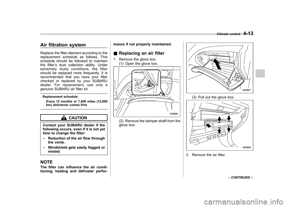
& Replacing an air filter
1. Remove the glove box. (1) Open the glove box.(2) Remove the damper shaft from the
glove box.
(3) Pull out the glove box.
2. Remove the air filter. Climate control
4-13
– CONTINUED –
Page 163 of 384
4-14Climate control
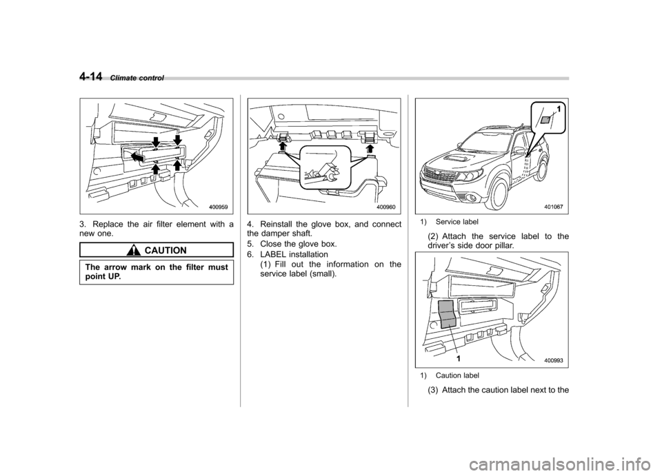
3. Replace the air filter element with a
new one.
CAUTION
The arrow mark on the filter must
point UP.
4. Reinstall the glove box, and connect
the damper shaft.
5. Close the glove box.
6. LABEL installation (1) Fill out the information on the
service label (small).1) Service label
(2) Attach the service label to the driver ’s side door pillar.
1) Caution label
(3) Attach the caution label next to the
Page 196 of 384
Interior lights....................................................... 6-2
Dome light .......................................................... 6-2
Cargo area light .................................................. 6-3
Map light ............................................................. 6-3
Sun visors ........................................................... 6-4
Vanity mirror ....................................................... 6-4
Storage compartment ......................................... 6-4
Glove box ........................................................... 6-5
Center console .................................................... 6-5
Overhead console ............................................... 6-6
Rear seat center table (if equipped) ..................... 6-6
Coin tray ............................................................. 6-7
Cup holders ......................................................... 6-7
Front passenger cup holder ................................. 6-7
Rear passenger cup holder (if equipped).. ............ 6-8Bottle holders
...................................................... 6-8
Accessory power outlets .................................... 6-9
Use with a cigarette lighter (dealer option)..... ..... 6-10
Floor mat ............................................................ 6-11
Shopping bag hook ........................................... 6-11
Coat hook ........................................................... 6-11
Cargo area cover (dealer option) ...................... 6-12
Using the cover ................................................. 6-12
To remove the cover .......................................... 6-12
To install the cover housing ............................... 6-13
Cargo tie-down hooks ....................................... 6-13
Under-floor storage compartment (if equipped) .................................................... 6-14Interior equipment
6
Page 200 of 384
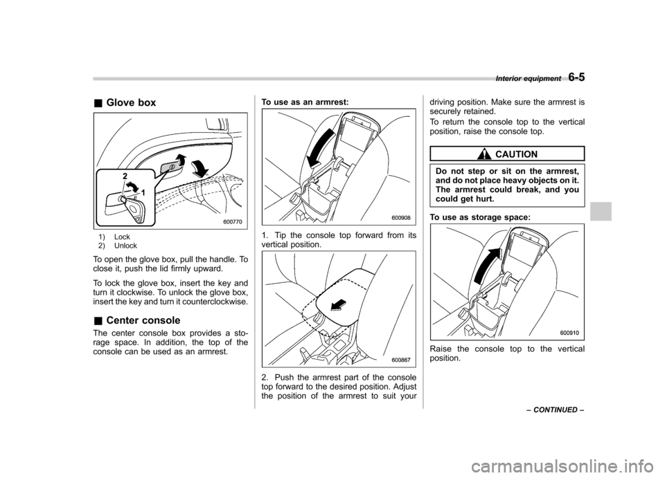
&Glove box
1) Lock
2) Unlock
To open the glove box, pull the handle. To
close it, push the lid firmly upward.
To lock the glove box, insert the key and
turn it clockwise. To unlock the glove box,
insert the key and turn it counterclockwise. & Center console
The center console box provides a sto-
rage space. In addition, the top of the
console can be used as an armrest. To use as an armrest:1. Tip the console top forward from its
vertical position.
2. Push the armrest part of the console
top forward to the desired position. Adjust
the position of the armrest to suit yourdriving position. Make sure the armrest is
securely retained.
To return the console top to the vertical
position, raise the console top.
CAUTION
Do not step or sit on the armrest,
and do not place heavy objects on it.
The armrest could break, and you
could get hurt.
To use as storage space:
Raise the console top to the vertical position. Interior equipment
6-5
– CONTINUED –
Page 376 of 384

Fuel........................................................................... 7-2
Economy hints ......................................................... 8-2
Filler lid and cap ...................................................... 7-3
Gauge .................................................................... 3-8
Requirements .......................................................... 7-2
Fuses ...................................................................... 11-44
Fuses and circuits ...................................................... 12-6
G
GAWR (Gross Axle Weight Rating) .............................. 8-13
Glove box ................................................................... 6-5
GVWR (Gross Vehicle Weight Rating) .......................... 8-13
H
Hazard warning flasher ........................................... 3-5, 9-2
Head restraint adjustment
Front seat ............................................................... 1-5
Rearseat ................................................................. 1-7
Headlight
Beam lever ........................................................... 3-26
Flasher ................................................................. 3-25
Indicator light ......................................................... 3-21
Headlights ........................................................ 3-24, 11-47
Heater operation (manual climate control system) ............ 4-5
High beam indicator light ............................................ 3-20
High/low beam change (dimmer) .................................. 3-25
Hill start assist (MT vehicles) .............................. 7-33, 11-29
Hill start assist warning light ................................ 3-17, 7-34
Horn ......................................................................... 3-38
Hose and connections ............................................... 11-12 I
Ignition switch
............................................................. 3-3
Light ...................................................................... 3-5
Illuminated entry .......................................................... 2-9
Illumination brightness control ...................................... 3-26
Immobilizer ................................................................. 2-2
Indicator light (security indicator light) ................. 2-3, 3-19
Indicator light Coolant temperature low .......................................... 3-13
Cruise control ................................................ 3-20, 7-37
Cruise control set ........................................... 3-21, 7-38
Front fog light ......................................................... 3-21
Headlight ............................................................... 3-21
High beam ............................................................. 3-20
Immobilizer ............................................................. 2-3
Security .......................................................... 2-3, 3-19
Selector lever/Gear position ..................................... 3-20
SPORT mode ........................................................ 3-20
Traction control system OFF .................................... 3-18
Turn signal ............................................................ 3-20
Vehicle Dynamics Control OFF ......................... 3-19, 7-28
Vehicle Dynamics Control operation .................. 3-18, 7-27
Information display ...................................................... 3-22
Inside mirror .............................................................. 3-33
Interior lights ............................................................... 6-2
J
Jack handle ............................................................... 9-17
Jump starting .............................................................. 9-9 Index
14-5