Page 65 of 135

(MR 411, 80A, Bat")
21B-5
SEQUENTIAL GEARBOX
Pressure accumulator: Removal - Refitting
D4F, and JH1
21B
REMOVAL
I - REMOVAL PREPARATION OPERATION
aRemove:
-the battery (see Battery: Removal - Refitting)
(MR 411, 80A, Battery),
-the sequential gearbox computer (see 21B, Se-
quential gearbox, Sequential gearbox convert-
er: Removal - Refitting, page 21B-47) ,
-the battery tray (see Battery tray: Removal - Re-
fitting) (MR 411, 80A, Battery),
-the petrol injection computer (see Petrol injection
computer: Removal - Refitting) (MR 411, 17B,
Petrol injection).
aDetach from the petrol injection computer mounting:
-the cooling hose,
-the sequential gearbox computer wiring harness,
-the petrol injection computer wiring harness,
-the battery wiring harness.aRemove:
-the petrol injection computer mounting nut (1) ,
-the engine wiring harness nut (2) from the petrol in-
jection computer mounting,
-the petrol injection computer mounting bolts (3) .
aRemove the engine wiring harness from the petrol
injection computer mounting.
aRemove the petrol injection computer mounting. Special tooling required
Mot. 445Oil filter strap wrench.
Equipment required
Diagnostic tool
IMPORTANT
Before carrying out any operation on the sequential
system, discharge the accumulator using the diag-
nostic tool.
IMPORTANT
Consult the safety and cleanliness advice and oper-
ation recommendations before carrying out any
repair (see 21B, Sequential gearbox, Sequential
gearbox: Precautions for the repair, page 21B-1)
.
Note:
To discharge the accumulator and deactivate the
pump assembly pump, (see Fault finding -
Replacement of components) (MR 413, 21B,
Sequential gearbox).
122323
122322
Page 66 of 135
21B-6
SEQUENTIAL GEARBOX
Pressure accumulator: Removal - Refitting
D4F, and JH1
21B
aDetach the breather pipe (4) :
-from the sequential gearbox lifting eye (5) ,
-from the cooling hose (6) .
aRemove:
-the breather pipe (4) from the sequential gearbox,
-the lifting eye nut (5) from the sequential gearbox,
-the lifting eye (5) from the sequential gearbox.aRemove the cooling hose.
aDisconnect the supply connector from the pump as-
sembly pump.
aDetach the pump assembly pump supply connector
from the electro-hydraulic unit connector mounting.
aRemove the electro-hydraulic unit wiring harness.
122314122313
Page 67 of 135
 from the actu-
ator module usi")
21B-7
SEQUENTIAL GEARBOX
Pressure accumulator: Removal - Refitting
D4F, and JH1
21B
II - OPERATION FOR REMOVAL OF PART
CONCERNED
a
aRemove the pressure accumulator (8) from the actu-
ator module using the (Mot. 445) (9) .
REFITTING
I - REFITTING PREPARATION OPERATION
aIf replacing the pressure accumulator, affix a safety
label to the accumulator.
aIt is essential to replace the pressure accumulator
seal.
II - REFITTING OPERATION FOR PART
CONCERNED
aRefit the pressure accumulator onto the actuator
module using the (Mot. 445).
III - FINAL OPERATION
aClip the pump assembly supply connector onto the
electro-hydraulic unit connector mounting.
aConnect the pump assembly supply connector.aRefit:
-the sequential gearbox lifting eye on the sequential
gearbox,
-the sequential gearbox lifting eye nut,
-the breather pipe on the sequential gearbox.
aAttach the breather pipe:
-to the cooling hose,
-to the sequential gearbox lifting eye.
aFit:
-the petrol injection computer support,
-the engine wiring harness on the petrol injection
computer mounting.
aRefit:
-the petrol injection computer mounting bolts,
-the engine wiring harness nut on the petrol injec-
tion computer mounting,
-the petrol injection computer mounting nut.
aClip onto the petrol injection computer mounting:
-the battery wiring harness,
-the petrol injection computer wiring harness,
-the sequential gearbox computer wiring harness,
-the cooling hose.
aRefit:
-the petrol injection computer (see Petrol injection
computer: Removal - Refitting) (MR 411, 17B,
Petrol injection),
-the battery tray (see Battery tray: Removal - Re-
fitting) (MR 411, 80A, Battery),
-the sequential gearbox computer (see 21B, Se-
quential gearbox, Sequential gearbox convert-
er: Removal - Refitting, page 21B-47) ,
-the battery (see Battery: Removal - Refitting)
(MR 411, 80A, Battery).
aFill the electric pump assembly reservoir with oil
(see Sequential gearbox oil: Specifications)
(Technical Note 6012, 04A, Lubricants) to between
32 and 38 mm above the MIN mark.
122315
Note:
Prepare for oil to flow out of the electro-hydraulic
unit.
WARNING
After the accumulator has been fully filled (15
seconds after the ignition has been switched on):
the oil level is at the MINIMUM mark.
Page 68 of 135
21B-8
SEQUENTIAL GEARBOX
Pressure accumulator: Removal - Refitting
D4F, and JH1
21B
aCarry out the necessary operations using the Diag-
nostic tool (see Fault finding - Replacement of
components) (MR 413, 21B, Sequential gearbox).
Page 69 of 135

21B-9
SEQUENTIAL GEARBOX
Pump assembly reservoir: Removal - Refitting
D4F, and JH1
21B
The electro-hydraulic unit comprises the pump assem-
bly and the actuator module.
REMOVAL
I - REMOVAL PREPARATION OPERATION
aPosition the vehicle on a two-post lift (see Vehicle:
Towing and lifting) (MR 411, 02A, Lifting equip-
ment).
aRemove:
-the battery (see Battery: Removal - Refitting)
(MR 411, 80A, Battery),
-the sequential gearbox computer (see 21B, Se-
quential gearbox, Sequential gearbox convert-
er: Removal - Refitting, page 21B-47) ,
-the battery tray (see Battery tray: Removal - Re-
fitting) (MR 411, 80A, Battery),
-the petrol injection computer (see Petrol injection
computer: Removal - Refitting) (MR 411, 17B,
Petrol injection).
-the rear suspended engine mounting (see Lower
engine tie-bar: Removal - Refitting) (MR 411,
19D, Engine mounting),
-the left-hand front wheel (see Wheel: Removal -
Refitting) (MR 411, 35A, Wheels and tyres),-the front left-hand wheel arch liner (see Front
wheel arch liner: Removal - Refitting) (MR 412,
55A, Exterior protection),
-the electro-hydraulic unit (see 21B, Sequential
gearbox, Electro-hydraulic unit: Removal - Re-
fitting, page 21B-11) ,
aPosition the (Ms. 583)
aSeparate
-the pump assembly from the electro-hydraulic unit
(see 21B, Sequential gearbox, Pump assembly:
Removal - Refitting, page 21B-18) .
II - OPERATION FOR REMOVAL OF PART
CONCERNED
aRemove the (Ms. 583) (1) from the low pressure
hose (2) .
aDrain the pump assembly reservoir.
aRemove:
-the bolts (3) from the pump assembly reservoir,
-the electric pump unit tank.
aIn the event of replacement, remove:
-the clip (4) from the low pressure hose (2) ,
-the low pressure hose (2) . Special tooling required
Ms. 583Pipe clamps .
Equipment required
Diagnostic tool
IMPORTANT
Consult the safety and cleanliness advice and oper-
ation recommendations before carrying out any
repair (see 21B, Sequential gearbox, Sequential
gearbox: Precautions for the repair, page 21B-1)
.
Note:
To discharge the accumulator and deactivate the
pump assembly pump, (see Fault finding -
Replacement of components) (MR 413, 21B,
Sequential gearbox).
122173
Page 70 of 135

21B-10
SEQUENTIAL GEARBOX
Pump assembly reservoir: Removal - Refitting
D4F, and JH1
21B
REFITTING
I - REFITTING PREPARATION OPERATION
aIn the event of replacement, refit:
-the low pressure hose,
-the low pressure hose clip.
aIt is essential to replace the pump assembly reser-
voir seal on the pump inlet.
II - REFITTING OPERATION FOR PART
CONCERNED
aRefit:
-the pump assembly reservoir,
-the pump assembly reservoir bolts.
III - FINAL OPERATION
aAssemble:
-the electro-hydraulic unit (see 21B, Sequential
gearbox, Electro-hydraulic unit: Removal - Re-
fitting, page 21B-11) ,
aRemove
-the pump assembly on the electro-hydraulic unit
(see 21B, Sequential gearbox, Pump assembly:
Removal - Refitting, page 21B-18) ,
-the front left-hand wheel arch liner (see Front
wheel arch liner: Removal - Refitting) (MR 412,
55A, Exterior protection),
-the left-hand front wheel (see Wheel: Removal -
Refitting) (MR 411, 35A, Wheels and tyres),
-the rear suspended engine mounting (see Lower
engine tie-bar: Removal - Refitting) (MR 411,
19D, Engine mounting),
-the petrol injection computer (see Petrol injection
computer: Removal - Refitting) (MR 411, 17B,
Petrol injection),
-the battery tray (see Battery tray: Removal - Re-
fitting) (MR 411, 80A, Battery),
-the sequential gearbox computer (see 21B, Se-
quential gearbox, Sequential gearbox convert-
er: Removal - Refitting, page 21B-47) ,
-the battery (see Battery: Removal - Refitting)
(MR 411, 80A, Battery).aFill the electric pump assembly reservoir with oil
(see Sequential gearbox oil: Specifications)
(Technical Note 6012, 04A, Lubricants) to between
32 and 38 mm above the MIN mark.
aCarry out the necessary operations using the Diag-
nostic tool (see Fault finding - Replacement of
components) (MR 413, 21B, Sequential gearbox). WARNING
After the accumulator has been fully filled (15
seconds after the ignition has been switched on):
the oil level is at the MINIMUM mark.
Page 71 of 135

21B-11
SEQUENTIAL GEARBOX
Electro-hydraulic unit: Removal - Refitting
D4F, and JH1
21B
The electro-hydraulic unit comprises the pump assem-
bly and the actuator module.
REMOVAL
I - REMOVAL PREPARATION OPERATION
aPosition the vehicle on a two-post lift (see Vehicle:
Towing and lifting) (MR 411, 02A, Lifting equip-
ment).
aRemove:
-the battery (see Battery: Removal - Refitting)
(MR 411, 80A, Battery),
-the sequential gearbox computer (see 21B, Se-
quential gearbox, Sequential gearbox convert-
er: Removal - Refitting, page 21B-47) ,-the battery tray (see Battery tray: Removal - Re-
fitting) (MR 411, 80A, Battery),
-the petrol injection computer (see Petrol injection
computer: Removal - Refitting) (MR 411, 17B,
Petrol injection).
aDetach from the petrol injection computer mounting:
-the cooling hose,
-the sequential gearbox computer wiring harness,
-the petrol injection computer wiring harness,
-the battery wiring harness. Special tooling required
Mot. 1390Suppor t for removal - refitting
of engine - gearbox assembly
Equipment required
Diagnostic tool
Tightening torquesm
left-hand suspended
engine mounting bolts21 N.m
left-hand suspended
engine mounting rubber
pad bolts62 N.m
left-hand suspended
engine mounting rubber
pad nut105 N.m
Note:
When replacing the electric pump assembly, always
replace the control relay.
IMPORTANT
Consult the safety and cleanliness advice and oper-
ation recommendations before carrying out any
repair (see 21B, Sequential gearbox, Sequential
gearbox: Precautions for the repair, page 21B-1)
.
Page 72 of 135
21B-12
SEQUENTIAL GEARBOX
Electro-hydraulic unit: Removal - Refitting
D4F, and JH1
21B
aRemove:
-the petrol injection computer mounting nut (1) ,
-the engine wiring harness nut (2) from the petrol in-
jection computer mounting,
-the petrol injection computer mounting bolts (3) .
aRemove the engine wiring harness from the petrol
injection computer mounting.
aRemove:
-the petrol injection computer support,-the rear suspended engine mounting (see Lower
engine tie-bar: Removal - Refitting) (MR 411,
19D, Engine mounting),
-the left-hand front wheel (see Wheel: Removal -
Refitting) (MR 411, 35A, Wheels and tyres),
-the front left-hand wheel arch liner (see Front
wheel arch liner: Removal - Refitting) (MR 412,
55A, Exterior protection).
aSupport the sequential gearbox on the (Mot. 1390).
122323
122322
17765
 1
1 2
2 3
3 4
4 5
5 6
6 7
7 8
8 9
9 10
10 11
11 12
12 13
13 14
14 15
15 16
16 17
17 18
18 19
19 20
20 21
21 22
22 23
23 24
24 25
25 26
26 27
27 28
28 29
29 30
30 31
31 32
32 33
33 34
34 35
35 36
36 37
37 38
38 39
39 40
40 41
41 42
42 43
43 44
44 45
45 46
46 47
47 48
48 49
49 50
50 51
51 52
52 53
53 54
54 55
55 56
56 57
57 58
58 59
59 60
60 61
61 62
62 63
63 64
64 65
65 66
66 67
67 68
68 69
69 70
70 71
71 72
72 73
73 74
74 75
75 76
76 77
77 78
78 79
79 80
80 81
81 82
82 83
83 84
84 85
85 86
86 87
87 88
88 89
89 90
90 91
91 92
92 93
93 94
94 95
95 96
96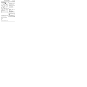 97
97 98
98 99
99 100
100 101
101 102
102 103
103 104
104 105
105 106
106 107
107 108
108 109
109 110
110 111
111 112
112 113
113 114
114 115
115 116
116 117
117 118
118 119
119 120
120 121
121 122
122 123
123 124
124 125
125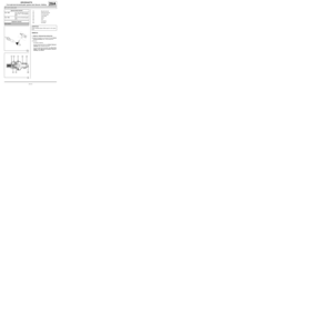 126
126 127
127 128
128 129
129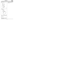 130
130 131
131 132
132 133
133 134
134 :
-from the sequential gearbox lifting eye (5) ,
-from the cooling hose (6) .
aRemove:")
 (MR")
 ,
-the engine wiring harness nut (2) from the petrol in-")