Page 105 of 135

21B-45
SEQUENTIAL GEARBOX
Sequential gearbox: Removal - Refitting
D4F, and JH1
21B
If replacing the sequential gearbox
aRefit:
-the sequential gearbox engine speed sensor (see
21B, Sequential gearbox, Sequential gearbox
engine speed sensor: Removal - Refitting, page
21B-38) ,
-the reverse gear switch (17) .
II - REFITTING OPERATION FOR PART
CONCERNED
aFit the sequential gearbox to the engine.
aFit the sequential gearbox studs without tightening
them.
aTorque tighten the sequential gearbox studs (7
Nm) using a roller-type stud removal tool.
aFit without tightening:
-the sequential gearbox bolts,
-the sequential gearbox nuts.
aTighten to torque:
-the sequential gearbox bolts (44 Nm),
-the sequential gearbox nuts (44 Nm).aRefit:
-the flywheel protection plate,
-the flywheel protection plate bolt.
aFit the flywheel protection plate bolts (18) without
tightening them.
aTorque tighten the flywheel protection plate bolts
(18) (44 Nm).
III - FINAL OPERATION
aAttach the engine wiring harness neck to the se-
quential gearbox.
aRefit the electro-hydraulic unit (see 21B, Sequential
gearbox, Electro-hydraulic unit: Removal - Refit-
ting, page 21B-11) .
aFit the « engine - sequential gearbox » assembly to
the front axle sub-frame using a workshop hoist
and a load balancer in its original position.
aRefit the « cooling radiator - cooling radiator hose »
assembly to the front axle sub-frame.
122163
122158
STANDARD HEATING
Page 106 of 135

21B-46
SEQUENTIAL GEARBOX
Sequential gearbox: Removal - Refitting
D4F, and JH1
21B
aRefit the « cooling radiator - cooling radiator hose -
air conditioning condenser » assembly to the front
axle sub-frame.
aConnect the cooling radiator bottom hose to the
coolant pump inlet pipe.
aRefit the cooling radiator bottom hose clip using the
(Mot. 1448).
aRefit:
-the air conditioning condenser inlet pipe,
-the air conditioning condenser inlet pipe bolt.
aRefit the sequential gearbox earth cable bolt.
aConnect the reverse gear switch connector.
aClip the wiring harness to the motor-driven fan as-
sembly.
aConnect:
-the motor-driven fan assembly resistor unit con-
nector,
-the motor-driven fan assembly connector.
aConnect the cooling radiator top hose to the water
chamber.
aRefit the cooling radiator top hose clip using the
(Mot. 1448).
aRefit:
-the engine speed and position sensor (see Crank-
shaft position sensor: Removal - Refitting) (MR
411, 17B, Petrol injection),
-the starter (see Starter: Removal - Refitting) (MR
411, 16A, Starting - Charging),
-the hub-carrier - driveshaft assembly (see ) (MR
411, 31A, Front axle components),
-the engine - gearbox assembly (see Engine -
gearbox assembly: Removal - Refitting) (MR
411, 10A, Engine and peripherals).aFill the refrigerant circuit (see Refrigerant circuit:
Draining - Filling) (MR 411, 62A, Air conditioning).
aRefill:
-the sequential gearbox (see 21A, Manual gear-
box, Manual gearbox oils: Draining - Filling,
page 21A-2) ,
-the cooling system (see Cooling system: Drain-
ing - Refilling) (MR 411, 19A, Cooling).
aRefit:
-the front bumper (see Front bumper: Removal -
Refitting) (MR 412, 55A, Exterior protection),
-the front wheel arch liners (see Front wheel arch
liner: Removal - Refitting) (MR 412, 55A, Exterior
protection),
-the catalytic converter (see Catalytic converter:
Removal - Refitting) ,
-the front wheels (see Wheel: Removal - Refitting)
(MR 411, 35A, Wheels and tyres),
-the air filter unit (see Air filter unit: Removal - Re-
fitting) (MR 411, 12A, Fuel mixture),
-the petrol injection computer (see Petrol injection
computer: Removal - Refitting) (MR 411, 17B,
Petrol injection),
-the battery tray (see Battery tray: Removal - Re-
fitting) (MR 411, 80A, Battery),
-the sequential gearbox computer (see 21B, Se-
quential gearbox, Sequential gearbox convert-
er: Removal - Refitting, page 21B-47) ,
-the battery (see Battery: Removal - Refitting)
(MR 411, 80A, Battery). AIR CONDITIONING or CLIMATE CONTROL
AIR CONDITIONING or CLIMATE CONTROL
AIR CONDITIONING or CLIMATE CONTROL
Page 107 of 135
21B-47
SEQUENTIAL GEARBOX
Sequential gearbox converter: Removal - Refitting
D4F, and JH1
21B
REMOVAL
I - REMOVAL PREPARATION OPERATION
aRemove the battery (see Battery: Removal - Refit-
ting) (MR 411, 80A, Battery).
II - OPERATION FOR REMOVAL OF PART
CONCERNED
aUnclip (1) the sequential gearbox computer from its
mounting (2) .aDisconnect the sequential gearbox computer con-
nectors (3) by pressing the locks.
aRemove the sequential gearbox computer.
REFITTING
I - REFITTING OPERATION FOR PART
CONCERNED
aConnect the sequential gearbox computer connec-
tors by pressing the locks.
aClip the sequential gearbox computer onto its
mounting.
II - FINAL OPERATION
aRefit the battery (see Battery: Removal - Refitting)
(MR 411, 80A, Battery).
aIf replacing the sequential gearbox computer, carry
out the necessary operations using the Diagnostic
tool (see Fault finding - Replacement of compo-
nents) (MR 413, 21B, Sequential gearbox). Equipment required
Diagnostic tool
122324
122325
Page 108 of 135
21B-48
SEQUENTIAL GEARBOX
Sequential gearbox gear lever: Removal - Refitting
D4F, and JH1
21B
REMOVAL
I - REMOVAL PREPARATION OPERATION
aUnclip the sequential gearbox gear lever cover (1) .II - OPERATION FOR REMOVAL OF PART
CONCERNED
aDisconnect the sequential gearbox gear lever con-
nector (2) .
aDetach the sequential gearbox gear lever connector
(2) .
aRemove:
-the sequential gearbox gear lever bolts (3) ,
-the sequential gearbox gear lever.
REFITTING
I - REFITTING OPERATION FOR PART
CONCERNED
aRefit:
-the sequential gearbox gear lever by positioning
the wiring harness at the front,
-the sequential gearbox gear lever bolts.
aClip on the sequential gearbox gear lever connector.
aConnect the sequential gearbox gear lever connec-
tor.
II - FINAL OPERATION.
aClip on the sequential gearbox gear lever cover.
122381
122380
Page 109 of 135
29A-1
DRIVESHAFTS
Driveshaft: Precautions for the repair
JB1 or JH1 or JH3 or JR5
29A
WARNING
A gearbox oil leak at the driveshaft may destroy it.
WARNING
Lubricate the base of the bearing with MOLYKOTE
to prevent the bear ing sticking.
Make sure that the O-ring is correctly positioned in
the base of the relay bearing, if the bearing has
one.
WARNING
Always replace seals whenever the driveshaft is
removed.
WARNING
Always replace the left-hand driveshaft lock ring, if
the driveshaft has one.
WARNING
In order to prevent irreversible damage to the front
hub bear ing:
-Do not loosen or tighten the driveshaft nut when
the wheels are on the ground.
-Do not place the vehicle with its wheels on the
ground when the driveshaft has been loosened or
removed.
Page 110 of 135
 (0")
29A-2
DRIVESHAFTS
Front left-hand driveshaft: Removal - Refitting
JB1 or JH1
29A
REMOVAL
I - REMOVAL PREPARATION OPERATION
aPosition the vehicle on a two-post lift (see Vehicle:
Towing and lifting) (02A, Lifting equipment).
aRemove:
-the engine undertray bolts,
-the engine undertray.
aDrain the manual gearbox (see 21A, Manual gear-
box, Manual gearbox oils: Draining - Filling, page
21A-2) .
aRemove the front left-hand wheel (see Wheel: Re-
moval - Refitting) (35A, Wheels and tyres).II - OPERATION FOR REMOVAL OF PART
CONCERNED
aDetach the wiring from the wheel speed sensor (1) .
aRemove:
-the hub nut (2) by immobilising the hub using the
tool (Rou. 604-01),
-the track rod end nut (3) ,
-the track rod end from the stub axle carrier using
the (Tav. 476),
-the shock absorber base bolts (4) . Special tooling required
Rou. 604-01Hub locking tool.
Tav. 476Ball joint extractor.
Tightening torquesm
the flange mounting
bolts21 Nm
shock absorber base
bolts105 N.m
track rod end nut37 Nm
hub nut280 N.m
WARNING
In order to prevent irreversible damage to the front
hub bear ing:
-Do not loosen or tighten the driveshaft nut when
the wheels are on the ground.
-Do not place the vehicle with its wheels on the
ground when the driveshaft has been loosened or
removed.
130488
Page 111 of 135
29A-3
DRIVESHAFTS
Front left-hand driveshaft: Removal - Refitting
JB1 or JH1
29A
aPush the front left-hand driveshaft back from the
stub axle carrier by pivoting the stub axle carrier.
aRemove:
-the bolts (5) securing the front left-hand driveshaft
to the gearbox,
-the front left-hand driveshaft.
REFITTING
I - REFITTING THE DRIVESHAFT
Special notes on the front left-hand driveshaft
130487
130489
107922
(6) Front left-hand driveshaft
(7) Bear ing gaiter (gearbox side)
(8) Gaiter flange
(9) Gaiter lip (for gearbox seal)
Page 112 of 135
 is made by pushing the gai-
ter lip (9) into its housing on the gearbox, moving the
flange (8)")
29A-4
DRIVESHAFTS
Front left-hand driveshaft: Removal - Refitting
JB1 or JH1
29A
aThe seal (gearbox side) is made by pushing the gai-
ter lip (9) into its housing on the gearbox, moving the
flange (8) .
Wipe oil from:
-the flange (8) ,
-between the flange and the gaiter,
-the seal lip (9) ,
-the face of the lip on the gearbox.
Refit the driveshaft on the gearbox side (this opera-
tion requires two people):
-Person 1:
•position the driveshaft at the differential input,
•fit the flange (8) on the gaiter (7) ,
•fit the driveshaft into the gearbox whilst keeping
the flange (8) on the gaiter,
•push the flange (8) to insert the gaiter lip (9) in its
housing (do not pinch the gaiter (7) ).
-Person 2:
•tighten the 3 flange mounting bolts (8) but do not
tighten fully (the flange should still be loose).
-Person 1:
•keep the driveshaft as horizontal as possible (with
respect to the differential).
-Person 2:
•torque tighten the flange mounting bolts (21
Nm).
aFit the front left-hand driveshaft into the stub axle
carrier.
aRefit the bolts to the shock absorber base.
aTorque tighten the shock absorber base bolts(105 N.m).
aPosition the track rod.
Torque tighten the track rod end nut (37 Nm).
aRefit the hub nut.
aTorque tighten the hub nut (280 N.m ) using the tool
(Rou. 604-01).
aClip on the wheel speed sensor wiring harness.
II - FINAL OPERATION.
aRefit the front left-hand wheel (see Wheel: Removal
- Refitting) (35A, Wheels and tyres).
aFill the gearbox (see 21A, Manual gearbox, Manu-
al gearbox oils: Draining - Filling, page 21A-2) .
aRefit the engine undertray. WARNING
To ensure a correct seal when refi tting a gaiter to
a gearbox:
-the flange (8) must be fitted to the gaiter (7)
(see figure 107922) in order to support the seal
lip (9) and to fit it correctly into its holder on the
gearbox.
Note:
The driveshaft must fit freely into the stub-axle
carrier until it protrudes enough for the hub nut to
be fitted.
 1
1 2
2 3
3 4
4 5
5 6
6 7
7 8
8 9
9 10
10 11
11 12
12 13
13 14
14 15
15 16
16 17
17 18
18 19
19 20
20 21
21 22
22 23
23 24
24 25
25 26
26 27
27 28
28 29
29 30
30 31
31 32
32 33
33 34
34 35
35 36
36 37
37 38
38 39
39 40
40 41
41 42
42 43
43 44
44 45
45 46
46 47
47 48
48 49
49 50
50 51
51 52
52 53
53 54
54 55
55 56
56 57
57 58
58 59
59 60
60 61
61 62
62 63
63 64
64 65
65 66
66 67
67 68
68 69
69 70
70 71
71 72
72 73
73 74
74 75
75 76
76 77
77 78
78 79
79 80
80 81
81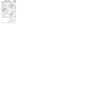 82
82 83
83 84
84 85
85 86
86 87
87 88
88 89
89 90
90 91
91 92
92 93
93 94
94 95
95 96
96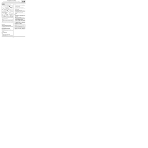 97
97 98
98 99
99 100
100 101
101 102
102 103
103 104
104 105
105 106
106 107
107 108
108 109
109 110
110 111
111 112
112 113
113 114
114 115
115 116
116 117
117 118
118 119
119 120
120 121
121 122
122 123
123 124
124 125
125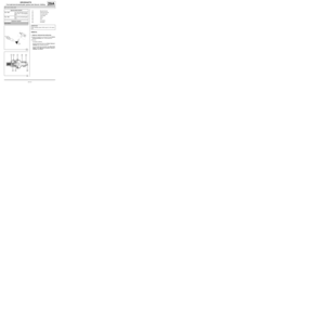 126
126 127
127 128
128 129
129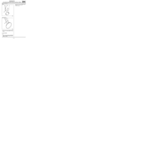 130
130 131
131 132
132 133
133 134
134 (MR 411,")
 .II - OPERA")

