Page 97 of 135
 from the solenoid
v")
21B-37
SEQUENTIAL GEARBOX
Solenoid valve assembly pressure sensor: Removal - Refitting
D4F, and JH1
21B
II - OPERATION FOR REMOVAL OF PART
CONCERNED
aDisconnect the connector (4) from the solenoid
valve unit pressure sensor.
aRemove the solenoid valve unit pressure sensor (5)
.
REFITTING
I - REFITTING PREPARATION OPERATION
aIt is essential to replace the solenoid valve unit pres-
sure sensor seal.
II - REFITTING OPERATION FOR PART
CONCERNED
aRefit the solenoid valve unit pressure sensor.
aConnect the solenoid valve unit pressure sensor
connector.
III - FINAL OPERATION
aFit:
-the petrol injection computer support,
-the engine wiring harness on the petrol injection
computer mounting.aRefit:
-the petrol injection computer mounting bolts,
-the engine wiring harness nut on the petrol injec-
tion computer mounting,
-the petrol injection computer mounting nut.
aClip:
-the battery wiring harness to the petrol injection
computer mounting,
-the petrol injection computer wiring harness to the
petrol injection computer mounting,
-the sequential gearbox computer wiring harness to
the petrol injection computer mounting,
-the cooling hose to the petrol injection computer
mounting.
aRefit:
-the petrol injection computer (see Petrol injection
computer: Removal - Refitting) (MR 411, 17B,
Petrol injection),
-the battery tray (see Battery tray: Removal - Re-
fitting) (MR 411, 80A, Battery),
-the sequential gearbox computer (see 21B, Se-
quential gearbox, Sequential gearbox convert-
er: Removal - Refitting, page 21B-47) ,
-the battery (see Battery: Removal - Refitting)
(MR 411, 80A, Battery).
aFill the electric pump assembly reservoir with oil
(see Sequential gearbox oil: Specifications)
(Technical Note 6012, 04A, Lubricants) to between
32 and 38 mm above the MIN mark.
aCarry out the necessary operations using the Diag-
nostic tool (see Fault finding - Replacement of
components) (MR 413, 21B, Sequential gearbox).
122317
Note:
Prepare for oil to flow out of the electro-hydraulic
unit.
WARNING
After the accumulator has been fully filled (15
seconds after the ignition has been switched on):
the oil level is at the MINIMUM mark.
Page 98 of 135

21B-38
SEQUENTIAL GEARBOX
Sequential gearbox engine speed sensor: Removal - Refitting
D4F, and JH1
21B
REMOVAL
I - REMOVAL PREPARATION OPERATION
aPosition the vehicle on a two-post lift (see Vehicle:
Towing and lifting) (MR 411, 02A, Lifting equip-
ment).
aRemove:
-the battery (see Battery: Removal - Refitting)
(MR 411, 80A, Battery),
-the sequential gearbox computer (see 21B, Se-
quential gearbox, Sequential gearbox convert-
er: Removal - Refitting, page 21B-47) ,
-the battery tray (see Battery tray: Removal - Re-
fitting) (MR 411, 80A, Battery),
-the petrol injection computer (see Petrol injection
computer: Removal - Refitting) (MR 411, 17B,
Petrol injection),
-the rear suspended engine mounting (see Lower
engine tie-bar: Removal - Refitting) (MR 411,
19D, Engine mounting),
-the left-hand front wheel (see Wheel: Removal -
Refitting) (MR 411, 35A, Wheels and tyres),
-the front left-hand wheel arch liner (see Front
wheel arch liner: Removal - Refitting) (MR 412,
55A, Exterior protection),
-the electro-hydraulic unit (see 21B, Sequential
gearbox, Electro-hydraulic unit: Removal - Re-
fitting, page 21B-11) .aRemove:
-the left-hand suspended engine mounting shaft
bolts (1) ,
-the left-hand suspended engine mounting shaft.
II - OPERATION FOR REMOVAL OF PART
CONCERNED
aRemove:
-the sequential gearbox engine speed sensor bolt
(2) ,
-the sequential gearbox engine speed sensor. Tightening torquesm
left-hand suspended
engine mounting shaft
bolts62 Nm
122161
122160
Page 99 of 135

21B-39
SEQUENTIAL GEARBOX
Sequential gearbox engine speed sensor: Removal - Refitting
D4F, and JH1
21B
REFITTING
I - REFITTING OPERATION FOR PART
CONCERNED
aRefit:
-the sequential gearbox engine speed sensor,
-the sequential gearbox engine speed sensor bolt.
II - FINAL OPERATION
aFit the left-hand suspended engine mounting shaft
onto the sequential gearbox.
aFit the left-hand suspended engine mounting shaft
bolts without tightening them.
aTorque tighten the left-hand suspended engine
mounting shaft bolts (62 Nm).
aRefit:
-the electro-hydraulic unit (see 21B, Sequential
gearbox, Electro-hydraulic unit: Removal - Re-
fitting, page 21B-11) ,
-the front left-hand wheel arch liner (see Front
wheel arch liner: Removal - Refitting) (MR 412,
55A, Exterior protection),
-the left-hand front wheel (see Wheel: Removal -
Refitting) (MR 411, 35A, Wheels and tyres),
-the rear suspended engine mounting (see Lower
engine tie-bar: Removal - Refitting) (MR 411,
19D, Engine mounting),
-the petrol injection computer (see Petrol injection
computer: Removal - Refitting) (MR 411, 17B,
Petrol injection),
-the battery tray (see Battery tray: Removal - Re-
fitting) (MR 411, 80A, Battery),
-the sequential gearbox computer (see 21B, Se-
quential gearbox, Sequential gearbox convert-
er: Removal - Refitting, page 21B-47) ,
-the battery (see Battery: Removal - Refitting)
(MR 411, 80A, Battery).
Page 100 of 135
")
21B-40
SEQUENTIAL GEARBOX
Sequential gearbox: Removal - Refitting
D4F, and JH1
21B
REMOVAL
I - REMOVAL PREPARATION OPERATION
aPosition the vehicle on a two-post lift (see Vehicle:
Towing and lifting) (MR 411, 02A, Lifting equip-
ment).
aRemove:
-the battery (see Battery: Removal - Refitting)
(MR 411, 80A, Battery),
-the sequential gearbox computer (see 21B, Se-
quential gearbox, Sequential gearbox convert-
er: Removal - Refitting, page 21B-47) ,
-the battery tray (see Battery tray: Removal - Re-
fitting) (MR 411, 80A, Battery),
-the petrol injection computer (see Petrol injection
computer: Removal - Refitting) (MR 411, 17B,
Petrol injection),-the air filter unit (see Air filter unit: Removal - Re-
fitting) (MR 411, 12A, Fuel mixture),
-the front wheels (see Wheel: Removal - Refitting)
(MR 411, 35A, Wheels and tyres),
-the catalytic converter (see Catalytic converter:
Removal - Refitting) ,
-the front wheel arch liners (see Front wheel arch
liner: Removal - Refitting) (MR 412, 55A, Exterior
protection),
-the front bumper (see Front bumper: Removal -
Refitting) (MR 412, 55A, Exterior protection).
aDrain:
-the cooling system (see Cooling system: Drain-
ing - Refilling) (MR 411, 19A, Cooling),
-the sequential gearbox (see 21A, Manual gear-
box, Manual gearbox oils: Draining - Filling,
page 21A-2) .
aDrain the refrigerant circuit (see Refrigerant circuit:
Draining - Filling) (MR 411, 62A, Air conditioning).
aRemove:
-the engine - gearbox assembly (see Engine -
gearbox assembly: Removal - Refitting) (MR
411, 10A, Engine and peripherals),
-the hub-carrier - driveshaft assembly (see ) (MR
411, 31A, Front axle components),
-the starter (see Starter: Removal - Refitting) (MR
411, 16A, Starting - Charging),
-the crankshaft position sensor (see Crankshaft
position sensor: Removal - Refitting) (MR 411,
17B, Petrol injection). Special tooling required
Mot. 1448Remote operation pliers for
hose clips .
Equipment required
workshop hoist
load balancer
roller-type stud removal tool
Tightening torquesm
sequential gearbox
studs7 Nm
sequential gearbox bolts44 Nm
sequential gearbox nuts44 Nm
flywheel protection plate
bolts (18)44 Nm
IMPORTANT
Consult the safety and cleanliness advice and oper-
ation recommendations before carrying out any
repair (see 21B, Sequential gearbox, Sequential
gearbox: Precautions for the repair, page 21B-1)
.
AIR CONDITIONING or CLIMATE CONTROL
Page 101 of 135
21B-41
SEQUENTIAL GEARBOX
Sequential gearbox: Removal - Refitting
D4F, and JH1
21B
aRemove the cooling radiator top hose clip (1) using
the (Mot. 1448).
aDisconnect the cooling radiator top hose (2) from the
water chamber.aDisconnect:
-the fan assembly connector (3) ,
-the resistor unit connector (4) from the blower unit.
aUnhook the electrical harness from fan assembly.
aDisconnect the connector (5) from the reverse gear
switch.
aRemove the sequential gearbox earth cable bolt (6) .
122155
WARNING
Prepare for the flow of fluid, and protect the sur-
rounding components.
122153
122154
Page 102 of 135
21B-42
SEQUENTIAL GEARBOX
Sequential gearbox: Removal - Refitting
D4F, and JH1
21B
aRemove:
-the air conditioning condenser inlet pipe bolt (7) ,
-the air conditioning condenser inlet pipe (8) .aRemove the cooling radiator bottom hose clip (9) us-
ing the (Mot. 1448).
aDisconnect the cooling radiator bottom hose (10)
from the coolant pump inlet pipe.
aRemove the « cooling radiator - cooling radiator
hose » assembly from the front axle sub-frame.
aRemove the « cooling radiator - cooling radiator
hose - air conditioning condenser » assembly from
the front axle sub-frame. AIR CONDITIONING or CLIMATE CONTROL
122156
122152
WARNING
Prepare for the flow of fluid, and protect the sur-
rounding components.
STANDARD HEATING
AIR CONDITIONING or CLIMATE CONTROL
Page 103 of 135
21B-43
SEQUENTIAL GEARBOX
Sequential gearbox: Removal - Refitting
D4F, and JH1
21B
aSeparate the « engine - sequential gearbox » as-
sembly from the front axle sub-frame using a work-
shop hoist and a load balancer.
aRemove the electro-hydraulic unit (see 21B, Se-
quential gearbox, Electro-hydraulic unit: Remov-
al - Refitting, page 21B-11) .
aRemove the sequential gearbox engine wiring har-
ness neck by pressing on the clip (11) .
aRemove the sequential gearbox engine wiring har-
ness neck.II - OPERATION FOR REMOVAL OF PART
CONCERNED
aRemove:
-the flywheel protection plate bolts (12) ,
-the flywheel protection plate.
122169
122159
122158
Page 104 of 135
21B-44
SEQUENTIAL GEARBOX
Sequential gearbox: Removal - Refitting
D4F, and JH1
21B
aRemove:
-the sequential gearbox nuts (13) ,
-the sequential gearbox bolts (14) ,
-the sequential gearbox from the engine,
-the sequential gearbox studs (15) using a roller-
type stud removal tool.If replacing the sequential gearbox
aRemove:
-the reverse gear switch (16) ,
-the sequential gearbox speed sensor (see 21B,
Sequential gearbox, Sequential gearbox engine
speed sensor: Removal - Refitting, page 21B-
38) .
REFITTING
I - REFITTING PREPARATION OPERATION
aCheck that the centring ring is in place.
122170
122157
122163
 1
1 2
2 3
3 4
4 5
5 6
6 7
7 8
8 9
9 10
10 11
11 12
12 13
13 14
14 15
15 16
16 17
17 18
18 19
19 20
20 21
21 22
22 23
23 24
24 25
25 26
26 27
27 28
28 29
29 30
30 31
31 32
32 33
33 34
34 35
35 36
36 37
37 38
38 39
39 40
40 41
41 42
42 43
43 44
44 45
45 46
46 47
47 48
48 49
49 50
50 51
51 52
52 53
53 54
54 55
55 56
56 57
57 58
58 59
59 60
60 61
61 62
62 63
63 64
64 65
65 66
66 67
67 68
68 69
69 70
70 71
71 72
72 73
73 74
74 75
75 76
76 77
77 78
78 79
79 80
80 81
81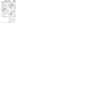 82
82 83
83 84
84 85
85 86
86 87
87 88
88 89
89 90
90 91
91 92
92 93
93 94
94 95
95 96
96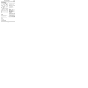 97
97 98
98 99
99 100
100 101
101 102
102 103
103 104
104 105
105 106
106 107
107 108
108 109
109 110
110 111
111 112
112 113
113 114
114 115
115 116
116 117
117 118
118 119
119 120
120 121
121 122
122 123
123 124
124 125
125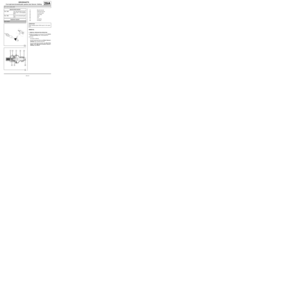 126
126 127
127 128
128 129
129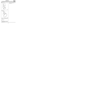 130
130 131
131 132
132 133
133 134
134 using
the (Mot. 1448).
aDisconnect the cooling radiator top hose (2) f")
 ,
-the air conditioning condenser inlet pipe (8) .aRemov")

 ,
-the sequential gearbox bolts (14) ,
-the sequential gearbox from the en")