Page 9 of 135
 (02A, Lifting equip")
20A-6
CLUTCH
Pressure plate - Disc: Removal - Refitting
K4M
20A
REMOVAL
I - REMOVAL PREPARATION OPERATION
aPosition the vehicle on a two-post lift (see Vehicle:
Towing and lifting) (02A, Lifting equipment).
aRemove:
-the engine undertray bolts,
-the engine undertray,
-the battery (see Battery: Removal - Refitting)
(80A, Battery)
-the air filter box (see Air filter unit: Removal - Re-
fitting) (12A, Fuel mixture),
-the petrol injection computer (see Petrol injection
computer: Removal - Refitting) (17B, Petrol in-
jection),
-the battery tray (see Battery tray: Removal - Re-
fitting) (80A, Battery),
-the front wheels (see Wheel: Removal - Refitting)
(35A, Wheels and tyres),
-the front wheel arch liners (see Front wheel arch
liner: Removal - Refitting) (55A, Exterior protec-
tion),
-the front bumper (see Front bumper: Removal -
Refitting) (55A, Exterior protection).
aDrain:
-the gearbox (see 21A, Manual gearbox, Manual
gearbox oils: Draining - Filling, page 21A-2) ,
-the engine cooling system (see Cooling system:
Draining - Refilling) (19A, Cooling),
-the refrigerant circuit (see Refrigerant circuit:
Draining - Filling) (62A, Air conditioning).aRemove:
-the rear suspended engine mounting (see Lower
engine tie-bar: Removal - Refitting) (19D, En-
gine mounting),
-the front axle subframe (see Front axle subframe:
Removal - Refitting) (31A, Front axle compo-
nents),
-the front left-hand driveshaft (see 29A, Drive-
shafts, Front left-hand driveshaft: Removal -
Refitting, page 29A-2) ,
-the front right-hand driveshaft (see 29A, Drive-
shafts, Front right-hand driveshaft: Removal -
Refitting, page 29A-8) .
-the engine - gearbox assembly (see Engine -
gearbox assembly: Removal - Refitting) (10A,
Engine and peripherals),
-the manual gearbox (see 21A, Manual gearbox,
Manual gearbox: Removal - Refitting, page 21A-
24) .
II - OPERATION FOR REMOVAL OF PART
CONCERNED
aPosition the (Mot. 1677) (1) .
aRemove:
-the clutch pressure plate bolts (2) ,
-the clutch pressure plate,
-the clutch plate. Special tooling required
Mot. 1677Flywheel locking tool.
Emb. 1780Set of clutch plate centr ing
mandrels.
Tightening torquesm
clutch pressure plate
bolts23 N.m
132329
Page 10 of 135
 (04B, Consuma-")
20A-7
CLUTCH
Pressure plate - Disc: Removal - Refitting
K4M
20A
REFITTING
I - REFITTING PREPARATION OPERATION
aUse SURFACE CLEANER (see Vehicle: Parts
and consumables for the repair) (04B, Consuma-
bles - Products) to clean and degrease:
-the flywheel friction face,
-the clutch shaft splines.
II - REFITTING OPERATION FOR PART
CONCERNED
aFit the clutch plate, with the face (3) to the clutch
pressure plate end.aCentre the clutch plate using the (Emb. 1780) (4) .
aRefit:
-the clutch pressure plate,
-the clutch pressure plate bolts by gradually tighten-
ing them in a radial pattern.
aTorque tighten the clutch pressure plate bolts (23
N.m).
aRemove the (Emb. 1780) and (Mot. 1677).
III - FINAL OPERATION.
aRefit:
-the manual gearbox (see 21A, Manual gearbox,
Manual gearbox: Removal - Refitting, page 21A-
24) ,
-the engine - gearbox assembly (see Engine -
gearbox assembly: Removal - Refitting) (10A,
Engine and peripherals),
-the front right-hand driveshaft (see 29A, Drive-
shafts, Front right-hand driveshaft: Removal -
Refitting, page 29A-8) .
-the front left-hand driveshaft (see 29A, Drive-
shafts, Front left-hand driveshaft: Removal -
Refitting, page 29A-2) ,
-the front axle subframe (see Front axle subframe:
Removal - Refitting) (31A, Front axle compo-
nents),
-the rear suspended engine mounting (see Lower
engine tie-bar: Removal - Refitting) (19D, En-
gine mounting). WARNING
Do not grease the clutch shaft splines.
132331
132332
Page 11 of 135
20A-8
CLUTCH
Pressure plate - Disc: Removal - Refitting
K4M
20A
aRefill:
-the engine cooling system (see Cooling system:
Draining - Refilling) (19A, Cooling),
-the gearbox (see 21A, Manual gearbox, Manual
gearbox oils: Draining - Filling, page 21A-2) ,
-the refrigerant circuit (see Refrigerant circuit:
Draining - Filling) (62A, Air conditioning).
aRefit:
-the front bumper (see Front bumper: Removal -
Refitting) (55A, Exterior protection).
-the front wheel arch liners (see Front wheel arch
liner: Removal - Refitting) (55A, Exterior protec-
tion),
-the front wheels (see Wheel: Removal - Refitting)
(35A, Wheels and tyres),
-the battery tray (see Battery tray: Removal - Re-
fitting) (80A, Battery),
-the petrol injection computer (see Petrol injection
computer: Removal - Refitting) (17B, Petrol in-
jection),
-the air filter box (see Air filter unit: Removal - Re-
fitting) (12A, Fuel mixture),
-the battery (see Battery: Removal - Refitting)
(80A, Battery)
-the engine undertray.
Page 12 of 135
 (02A, Liftin")
20A-9
CLUTCH
Clutch thrust bearing: Removal - Refitting
JH3 or JR5
20A
REMOVAL
I - REMOVAL PREPARATION OPERATION
aPosition the vehicle on a two-post lift (see Vehicle:
Towing and lifting) (02A, Lifting equipment).
aRemove:
-the engine undertray bolts,
-the engine undertray,
-the gearbox (see 21A, Manual gearbox, Manual
gearbox: Removal - Refitting, page 21A-24) .
II - OPERATION FOR REMOVAL OF PART
CONCERNED
aRemove the clutch thrust bearing bolts (1) .aRemove the clutch thrust bearing (2) .
REFITTING
I - REFITTING PREPARATION OPERATION
a
II - REFITTING OPERATION FOR PART
CONCERNED
aRefit the clutch thrust bearing. Tightening torquesm
clutch thrust bearing
bolts (JH3)21 N.m
clutch thrust bearing
bolts (JR5)25 N.m
Note:
The clutch thrust bear ing cannot be separated from
the clutch slave cylinder.
108796
108797
WARNING
Prepare for the flow of fluid, and protect the sur-
rounding components.
WARNING
To avoid damaging the slave cylinder, do not coat
the gearbox output shaft with grease.
WARNING
Never operate the system when the slave cylin-
der is removed (even if it is connected to the
clutch pedal). There is a risk that the hydraulic
piston and the sla ve cylinder stop will be ejected.
Note:
To obtain optimum bleeding, pre-fill the clutch
thrust bearing when refitting the thrust bearing.
Page 13 of 135
20A-10
CLUTCH
Clutch thrust bearing: Removal - Refitting
JH3 or JR5
20A
aTorque tighten the clutch thrust bearing bolts
(JH3) (21 N.m).
aTorque tighten the clutch thrust bearing bolts
(JR5) (25 N.m).
III - FINAL OPERATION.
aRefit the gearbox (see 21A, Manual gearbox, Man-
ual gearbox: Removal - Refitting, page 21A-24) .
aBleed the clutch control (see Clutch circuit: Bleed)
(37A, Mechanical component controls).
aRefit the engine undertray. JH3
JR5
Page 14 of 135
20A-11
CLUTCH
Clutch thrust bearing: Removal - Refitting
JB1
20A
REMOVAL
I - REMOVAL PREPARATION OPERATION
aPosition the vehicle on a two-post lift (see Vehicle:
Towing and lifting) (MR 411, 02A, Lifting equip-
ment).
aDisconnect the battery (see Battery: Removal - Re-
fitting) (MR 411, 80A, Battery).
aRemove the gearbox (see 21A, Manual gearbox,
Manual gearbox: Removal - Refitting, page 21A-
24) .
II - OPERATION FOR REMOVAL OF PART
CONCERNED
aRemove the clutch thrust bearing (1) by tilting the
fork at (A) .aRemove the fork (2) by pulling it towards the inside
of the clutch housing.
REFITTING
I - REFITTING PREPARATIONS OPERATION
aCheck that there are no leaks from the input shaft,
replace the guide tube if necessary (see 21A, Man-
ual gearbox, Input shaft lip seal: Removal - Refit-
ting, page 21A-41) .
aCoat the walls of the guide tube and the fork pads
with BR2+ GREASE.
107917
107914
Page 15 of 135
20A-12
CLUTCH
Clutch thrust bearing: Removal - Refitting
JB1
20A
II - REFITTING OPERATION FOR PART
CONCERNED
aRefit the fork.
aRefit:
-the fork,
-the stop on the guide tube, placing the hooks (3)
into the fork.
aEnsure that it slides correctly.
III - FINAL OPERATION.
aRefit the gearbox (see 21A, Manual gearbox, Man-
ual gearbox: Removal - Refitting, page 21A-24) .aAfter refitting the gearbox, check the travel (X) of the
fork.
This must be:
-D4F engine: x = 29.5 mm ±± ± ±
0.5,
-D7F engine: x = 29.5 mm ±± ± ±
0.5.
aConnect the battery (see Battery: Removal - Refit-
ting) (MR 411, 80A, Battery).
107916
Note:
During operations where the gearbox does not
have to be removed or refitted, do not lift the fork
because this may cause the hooks to come out
(3) of the thrust bearing.
91830
Page 16 of 135

21A-1
MANUAL GEARBOX
Manual gearbox oil: Specifications
5-SPEED MANUAL GEARBOX
21A
I - GEARBOX TYPE/OIL TYPE CORRELATIONS:
Component identification:
The third character X corresponds to the figure written
on the identification plate and therefore covers the en-
tire manual gearbox range.
II - STANDARDS AND PART NUMBERS OF THE
VARIOUS RECOMMENDED OILS:III - IDENTIFICATION OF OIL FOR STANDARD
EXCHANGE PK1 GEARBOXES: GEARBOX TYPE TYPE OF OIL FOR
GEARBOX
JBX
JCX
JRX
JHX
NDX
TLXTRANSELF TRJ
75W80
or
TRANSELF NFJ
75W80
PKX
PFX
VMX
NEX
NGX
N0X
UNXTRANSELF TRX
75W80
or
TRANSELF NFP
75W80
ZFX T RANSELF LD
75W80
DESIGNATION STANDARDPART NUM-
BER
TRANSELF
TRX 75W80
or
TRANSELF
NFP 75W80APIGL4,
MIL-L-2105
C or D77 11 143 534
(5 litres)TRANSELF
TRJ 75W80
or
TRANSELF
NFJ 75W80APIGL4,
MIL-L-2105
C or DMay be
ordered from
ELF
TRANSELF
LD 75W80APIGL4,
MIL-L-2105May be
ordered from
ELF
Note:
For standard exchange PK1 gearboxes, the oil type
(TRZ or TRP) is shown on a label.
These two oils are replaced by TRX 75W80 or NFP
75W80.
 1
1 2
2 3
3 4
4 5
5 6
6 7
7 8
8 9
9 10
10 11
11 12
12 13
13 14
14 15
15 16
16 17
17 18
18 19
19 20
20 21
21 22
22 23
23 24
24 25
25 26
26 27
27 28
28 29
29 30
30 31
31 32
32 33
33 34
34 35
35 36
36 37
37 38
38 39
39 40
40 41
41 42
42 43
43 44
44 45
45 46
46 47
47 48
48 49
49 50
50 51
51 52
52 53
53 54
54 55
55 56
56 57
57 58
58 59
59 60
60 61
61 62
62 63
63 64
64 65
65 66
66 67
67 68
68 69
69 70
70 71
71 72
72 73
73 74
74 75
75 76
76 77
77 78
78 79
79 80
80 81
81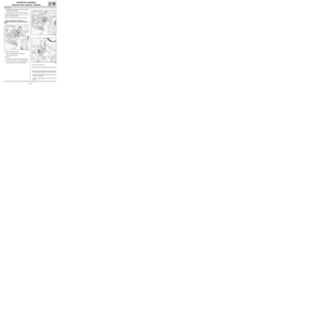 82
82 83
83 84
84 85
85 86
86 87
87 88
88 89
89 90
90 91
91 92
92 93
93 94
94 95
95 96
96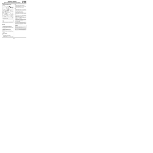 97
97 98
98 99
99 100
100 101
101 102
102 103
103 104
104 105
105 106
106 107
107 108
108 109
109 110
110 111
111 112
112 113
113 114
114 115
115 116
116 117
117 118
118 119
119 120
120 121
121 122
122 123
123 124
124 125
125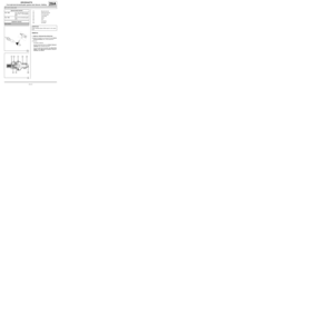 126
126 127
127 128
128 129
129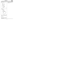 130
130 131
131 132
132 133
133 134
134 (19A, Cooling),
-the gearbox (see 21A, Manual gearbox, Ma")
 (21 N.m).
aTorque tighten the clutch thrust bearing bolts
(JR5) (25 N.m).")
 (MR 411, 02A, Lift")

in")