Page 25 of 209
40A-20
GENERAL INFORMATION
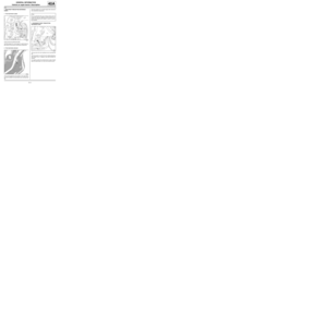
Vehicle structure, centre section: Description
40A
(7) Rear floor front cross member (see 41D, Rear lower structure, Rear floor front cross
member: Description, page 41D-12)
(8) Rear floor centre cross member (see 41D, Rear lower structure, Rear floor centre cross
member: Description, page 41D-14)
(9) Rear floor (see 41D, Rear lower structure, Rear floor: Description,
page 41D-1) No. Description Classification Type Thickness
(mm)
Page 26 of 209
40A-21
GENERAL INFORMATION
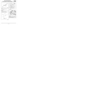
Vehicle structure, rear section: Description
40A
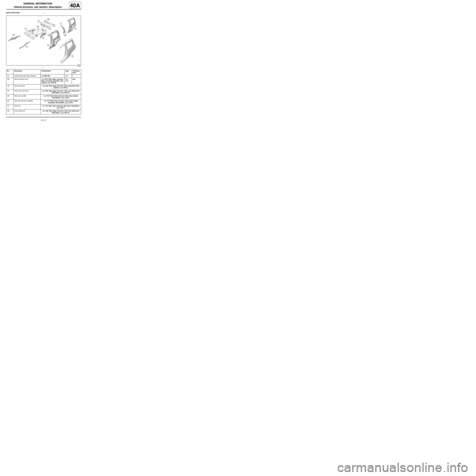
REAR STRUCTURE
120917
No. Description Classification Type Thickness
(mm)
(1) Quarter panel rear upper stiffener (see MR 400)HLE1
(2) Rear end panel lining (see 44A, Rear upper structure,
Rear end panel assembly: Des-
cription, page 44A-22) Mild
steel0.95
(3) Rear wing panel (see 44A, Rear upper structure, Rear wing panel: Des-
cription, page 44A-2)
(4) Outer rear wheel arch (see 44A, Rear upper structure, Outer rear wheel arch:
Description, page 44A-10)
(5) Rear side member (see 41D, Rear lower structure, Rear side member:
Description, page 41D-8)
(6) Rear side member assembly (see 41D, Rear lower structure, Rear side member
assembly: Description, page 41D-5)
(7) Rear floor (see 41D, Rear lower structure, Rear floor: Description,
page 41D-1)
(8) Inner wheel arch (see 44A, Rear upper structure, Inner rear wheel arch:
Description, page 44A-14)
Page 27 of 209
40A-22
GENERAL INFORMATION
Vehicle structure, rear section: Description
40A
(9) Rear light mounting (see 44A, Rear upper structure, Rear lights mounting:
Description, page 44A-6)
(10) Rear towing eye (see 41D, Rear lower structure, Rear towing eye: Des-
cription, page 41D-16)
(11) Quarter panel lining (see 44A, Rear upper structure, Quarter panel lining:
Description, page 44A-17)
(12) Rear end panel (see 44A, Rear upper structure, Rear end panel: Des-
cription, page 44A-25) No. Description Classification Type Thickness
(mm)
Page 28 of 209
40A-23
GENERAL INFORMATION
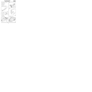
Vehicle structure, removable section: Description
40A
REMOVABLE STRUCTURE
121745
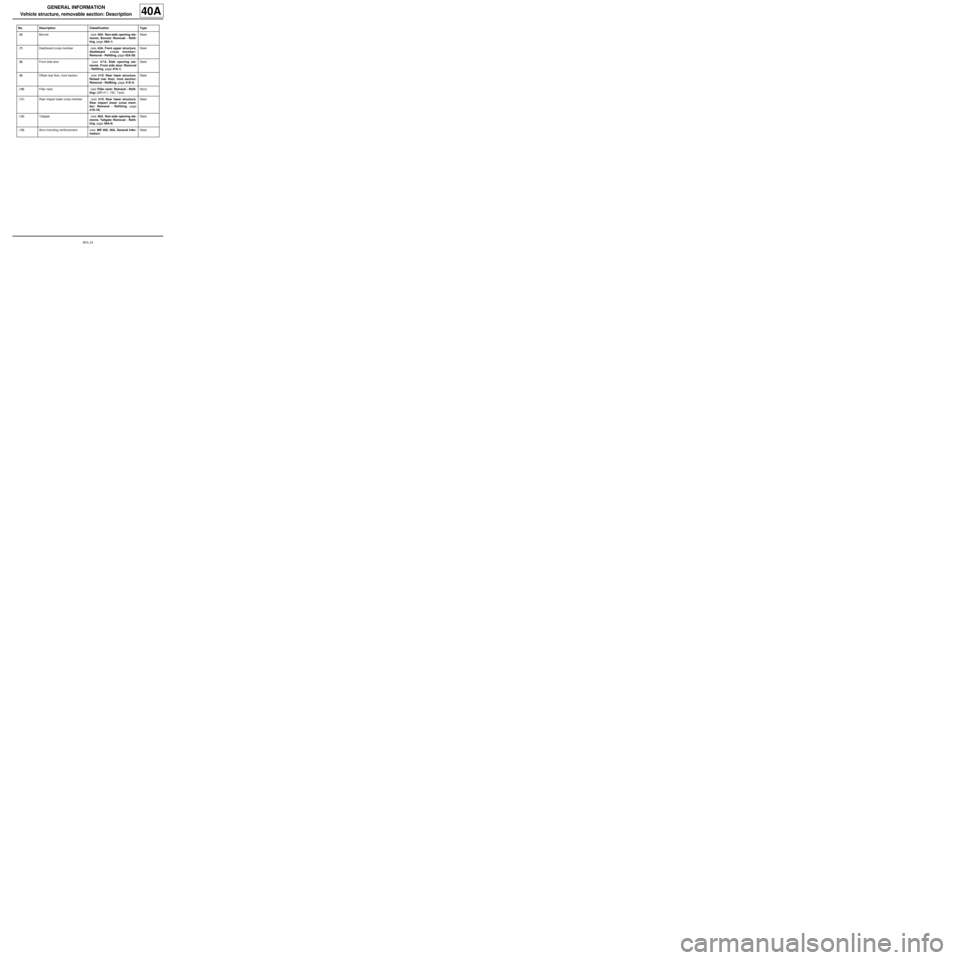
No. Description Classification Type
(1) Radiator mounting cross member (see 41A, Front lower structure,
Radiator mounting cross mem-
ber: Removal - Refitting, page
41A-5) Steel
(2) Headlight carrier panel (see 42A, Front upper structure,
Headlight carrier panel: Remo-
val - Refitting, page 42A-11) Steel
(3) Front upper cross member (see 42A, Front upper structure,
Front upper cross member:
Removal - Refitting, page 42A-13) Steel
(4) Front wing (see 42A, Front upper structure,
Front wing: Removal - Refitting,
page 42A-3) Noryl
(5) Front wing mounting support (see 42A, Front upper structure,
Front wing upper mounting sup-
port: Removal - Refitting, page
42A-7) Steel
Page 29 of 209

40A-24
GENERAL INFORMATION
Vehicle structure, removable section: Description
40A
(6) Bonnet (see 48A, Non-side opening ele-
ments, Bonnet: Removal - Refit-
ting, page 48A-1) Steel
(7) Dashboard cross member (see 42A, Front upper structure,
Dashboard c ross member:
Removal - Refitting, page 42A-26) Steel
(8) Front side door (see 47A, Side opening ele-
ments, Front side door: Removal
- Refitting, page 47A-1) Steel
(9) Offset rear floor, front section (see 41D, Rear lower structure,
Raised rear floor, front section:
Removal - Refitting, page 41D-4) Steel
(10) Filler neck (see Filler neck: Removal - Refit-
ting) (MR 411, 19C, Tank)Noryl
(11) Rear impact lower cross member (see 41D, Rear lower structure,
Rear impact lower cross mem-
ber: Removal - Refitting, page
41D-18) Steel
(12) Tailgate (see 48A, Non-side opening ele-
ments, Tailgate: Removal - Refit-
ting, page 48A-6) Steel
(13) Strut mounting reinforcement (see: MR 400, 40A, General infor-
mation)Steel No. Description Classification Type
Page 30 of 209
40A-25
GENERAL INFORMATION
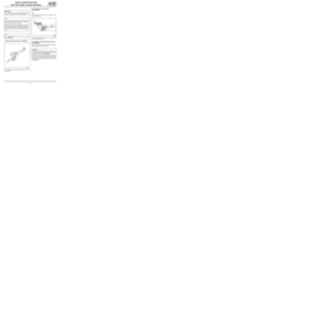
Structural components to be positioned on the repair bench: Description40A
I - PARTS REQUIRING THE USE OF A BODY JIG
BENCH
(1) Front wheel arch
(2) Front half-unit
(3) Engine mounting
(4) Subframe left-hand front mounting
(5) Front side member front section
(6) Rear side member rear section
(7) Rear side member
(8) Rear side member assembly
(9) Rear floor centre cross member
(10) Inner rear wheel archII - FRONT SUBFRAME REAR MOUNTING
121751
121747
Page 31 of 209

40A-26
GENERAL INFORMATION
Structural components to be positioned on the repair bench: Description40A
The jig rests against the rear section of the side mem-
ber and is centred in the sub-frame rear mounting hole
(11) .
The jig is used for replacing a complete front half unit.
III - REAR AXLE ASSEMBLY FRONT MOUNTING
The jig supports the underneath of the rear axle as-
sembly mounting unit and is centred on threaded hole
(12) of the rear axle bearing mounting.
The jig is used for replacing a rear side member as-
sembly.IV - FRONT SUBFRAME FRONT MOUNTING
The jig supports the underneath of the front sub-frame
mounting and is centred on tapped hole (13) .
The jig is used to replace:
-a complete front side member,
-a front half unit. IMPORTANT
This point contributes to ensuring the front axle
geometry. This point aligns the subframe of the
front axle in relation to the body. This point has a
direct influence on all of the front axle angles.
121746
IMPORTANT
These points contribute to ensuring the alignment
of the rear axle in relation to the body. These points
have a direct influence on all of the path angles of
the vehicle.
121752
IMPORTANT
This point contributes to ensuring the front axle
geometry. This point aligns the subframe of the
front axle in relation to the body. This point has a
direct influence on all of the front axle angles.
Page 32 of 209

40A-27
GENERAL INFORMATION
Structural components to be positioned on the repair bench: Description40A
V - FRONT SHOCK ABSORBER UPPER MOUNTING
The jig supports the underneath of the shock absorber
cup and is centred on the hole (14) of the shock absor-
ber cup.
The jig is used to replace:
-a wheel arch,
-a front half unit.
The jig is also used in straightening.VI - ENGINE MOUNTING
The jig rests on the engine mounting and is centred on
engine mounting securing holes (15) .
The jig is used with the subframe removed for the re-
placement of:
-a front half unit.
-the engine mounting.
VII - FRONT IMPACT CROSS MEMBER MOUNTING
The jig rests vertically against the front end lower cross
member mounting unit, it is centred in the mounting ho-
les (16) .
The jig is used to replace:
-the radiator cross member mounting,
-the front side member completely or partially,.
121753
IMPORTANT
This point contributes to ensuring the front axle
geometry. This point aligns the subframe of the
front axle in relation to the body. This point has a
direct influence on all of the front axle angles.
121753
121754