Page 137 of 209
42A-28
FRONT UPPER STRUCTURE
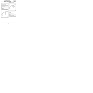
Windscreen aperture lower cross member closure panel: Description42A
There is only one way of replacing this part:
-partial replacement.
I - COMPOSITION OF THE SPARE PART
II - PART IN POSITION
Partial replacementIII - POSITIONING OF LOCAL ELECTRICAL
EARTHS
121055
No. Description Type Thic-
kness
(mm)
(1) Windscreen
apert u r e l o wer
cross member
closure panelMild
steel0.75
121238
WARNING
If the spot welds cannot be made as they were ori-
ginally using an electrical spot welding machine,
they should be replaced with plug welds after holes
have been drilled in the first panel.
121246
IMPORTANT
To avoid damaging the vehicle's electric and elec-
tronic components, the battery and the earths of
any wiring harness near the weld area must be dis-
connected.
The earth of the welding machine must be placed
as close as possible to the weld area.
Page 138 of 209
43A-1
SIDE UPPER STRUCTURE
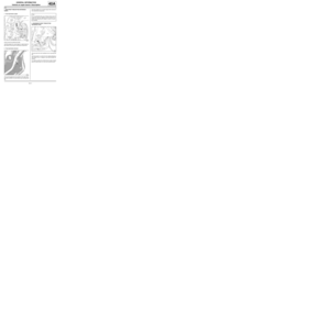
A-pillar: General description
43A
DESIGN OF THE STRUCTURAL COMPONENT
The design of this part is identical for all three vehicles.
On the Modus, the A-pillar is obtained by extension
from the body side front section.WARNING
The information contained in the following descri-
bes the general repair procedure for all vehicles
having the same design for this part.
Before reading the following general information,
make sure that there are no special notes associa-
ted with the vehicle. These special notes are speci-
fied if necessary in other par ts of the sub-section
dealing with the component.
Note:
For a detailed description of a particular connec-
tion, see MR 400, 40A, General Information.
109562
WARNING
If the spot welds cannot be made as they were ori-
ginally using an electrical spot welding machine,
they should be replaced with plug welds after holes
have been drilled in the first panel.
Page 139 of 209
43A-2
SIDE UPPER STRUCTURE
A-pillar: Description
43A
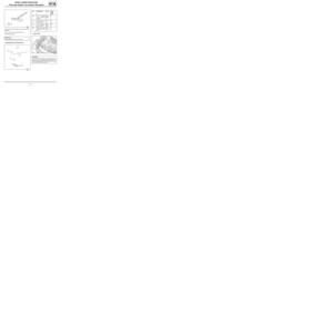
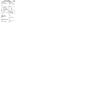
To replace this part, order the A-pillar expanding insert
(A) .
The options for replacing this part are as follows:
-partial replacement of the lower front section,
-front partial replacement,
-complete replacement.
I - COMPOSITION OF THE SPARE PARTII - PART IN POSITION
1 - Partial replacement of the lower front section
Section B
125412
121228
No. Description Type Thic-
kness
(mm)
(1) Body side Mild
steel0.75
120992
120991
Page 140 of 209
43A-3
SIDE UPPER STRUCTURE
A-pillar: Description
43A
Section C
2 - Partial front replacementSection D
3 - Complete replacement
120994
WARNING
Respect the position of this cut which has been
determined in accordance with the position of the
inner stiffeners or acoustic inserts, in order to pre-
vent damaging the parts (inner stiffener and/or
acoustic inser t).
120993
120996
WARNING
Respect the position of this cut which has been
determined in accordance with the position of the
inner stiffeners or acoustic inserts, in order to pre-
vent damaging the parts (inner stiffener and/or
acoustic inser t).
120990
Page 141 of 209
43A-4
SIDE UPPER STRUCTURE
A-pillar: Description
43A
Section E III - POSITIONING OF LOCAL ELECTRICAL
EARTHS
120989
Note:
For more detailed information on welded connec-
tions with three thicknesses, see MR 400.
IMPORTANT
If the mating faces of the parts to be welded are not
accessible, make EGW plug welds to replace the
original resistance welds (see MR 400).
121245
WARNING
To avoid damaging the vehicles electric and electro-
nic components, the earths of any wiring harness
near the weld area must be disconnected.
Position the earth of the welding machine as closely
as possible to the weld area (see MR 400).
Page 142 of 209
43A-5
SIDE UPPER STRUCTURE
A-pillar reinforcement: General description
43A
DESIGN OF THE STRUCTURAL COMPONENT
This is a basic part, its only function is that of an A-pillar
reinforcement.WARNING
The information contained in the following descri-
bes the general repair procedure for all vehicles
having the same design for this part.
Before reading the following general information,
make sure that there are no special notes associa-
ted with the vehicle. These special notes are speci-
fied if necessary in other par ts of the sub-section
dealing with the component.
Note:
For a detailed description of a particular connec-
tion, see MR 400, 40A, General Information.
112718
WARNING
If the spot welds cannot be made as they were ori-
ginally using an electrical spot welding machine,
they should be replaced with plug welds after holes
have been drilled in the first panel.
Page 143 of 209
43A-6
SIDE UPPER STRUCTURE
A-pillar reinforcement: Description
C44
43A
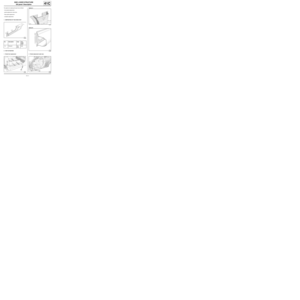
To replace this part, order the A-pillar reinforcement
expanding insert (A) .
There is only one way of replacing this part:
-complete replacement.
I - COMPOSITION OF THE SPARE PARTII - PART IN POSITION
Complete replacement
125407
120997
No. Description Type Thic-
kness
(mm)
(1) Lower hinge rein-
forcementHEL1.5
(2) Upper hinge rein-
forcementHEL2
(3) A-pillar reinforce-
mentHEL0.95
120998
Note:
For more detailed information on welded connec-
tions with three thicknesses, see MR 400.
IMPORTANT
If the mating faces of the parts to be welded are not
accessible, make EGW plug welds to replace the
original resistance welds (see MR 400).
Page 144 of 209
43A-7
SIDE UPPER STRUCTURE
A-pillar reinforcement: Description
C44
43A
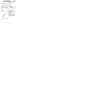
III - POSITIONING OF LOCAL ELECTRICAL
EARTHS
121245
WARNING
To avoid damaging the vehicles electric and electro-
nic components, the earths of any wiring harness
near the weld area must be disconnected.
Position the earth of the welding machine as closely
as possible to the weld area (see MR 400).