Page 105 of 209
41D-14
REAR LOWER STRUCTURE
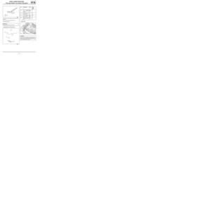
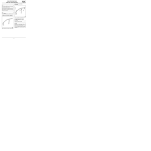
Rear floor centre cross member: Description
C44
41D
There is only one way of replacing this part:
-complete replacement.
I - COMPOSITION OF THE SPARE PARTII - PART FITTED
120932
IMPORTANT
Use a repair bench to ensure the positioning of the
points and the geometr y of the axle assemblies.
120910
No. Description Type Thic-
kness
(mm)
(1) Rear centre
cross memberHLE1.2
(2) Rear axle bea-
ring spacerHLE2.5
(3) Rear axle bea-
ring spacer
mountingHLE2.5
(4) Rear seatback
stiffener moun-
tingHLE1.2
120911
IMPORTANT
If the mating faces of the parts to be welded are not
accessible, make EGW plug welds to replace the
original resistance welds (see MR 400). No. Description Type Thic-
kness
(mm)
Page 106 of 209
41D-15
REAR LOWER STRUCTURE
Rear floor centre cross member: Description
C44
41D
III - POSITIONING OF LOCAL ELECTRICAL
EARTHS
121249
WARNING
To avoid damaging the vehicles electric and electro-
nic components, the earths of any wiring harness
near the weld area must be disconnected.
Position the earth of the welding machine as closely
as possible to the weld area (see MR 400).
Page 107 of 209
41D-16
REAR LOWER STRUCTURE
Rear towing eye: Description
41D
There is only one way of replacing this part:
-complete replacement.
I - COMPOSITION OF THE SPARE PARTII - PART FITTED
120931
120908
No. Description Type Thic-
kness
(mm)
(1) Rear tow eye
mountingMild
steel1.8
(2) Rear towing and
lashing wireMild
steel∅ 10
120909
WARNING
If the spot welds cannot be made as they were ori-
ginally using an electrical spot welding machine,
they should be replaced with plug welds after holes
have been drilled in the first panel.
Page 108 of 209
41D-17
REAR LOWER STRUCTURE
Rear towing eye: Description
41D
III - POSITIONING OF LOCAL ELECTRICAL
EARTHS
121249
IMPORTANT
To avoid damaging the vehicle's electric and elec-
tronic components, the battery and the earths of
any wiring harness near the weld area must be dis-
connected.
The earth of the welding machine must be placed
as close as possible to the weld area.
Page 109 of 209
41D-18
REAR LOWER STRUCTURE
Rear impact lower cross member: Removal - Refitting41D
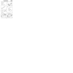
REMOVAL
I - REMOVAL PREPARATION OPERATION
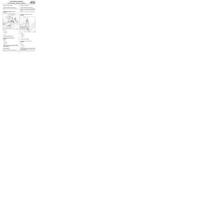
aPosition the vehicle on a two-post lift (see Vehicle:
Towing and lifting) (MR 412, 02A, Lifting equip-
ment).
aRemove:
-the rear lights on the wing (see Rear wing light:
Removal - Refitting) (MR 411, 81A, Rear lighting),
-the rear bumper (see Rear bumper: Removal -
Refitting) (MR 412, 55A, Exterior protection).
II - OPERATION FOR REMOVAL OF PART
CONCERNED
aRemove:
-the nuts (1) ,
-the rear impact lower cross member.
REFITTING
I - REFITTING OPERATION FOR PART
CONCERNED
aRefit:
-the rear impact lower cross member,
-the nuts (1) .II - FINAL OPERATION.
aRefit:
-the rear bumper (see Rear bumper: Removal -
Refitting) (MR 412, 55A, Exterior protection),
-the rear lights on the wing (see Rear wing light:
Removal - Refitting) (MR 411, 81A, Rear lighting).
121146
Page 110 of 209

42A-1
FRONT UPPER STRUCTURE
Front wing: General description
42A
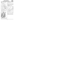
I - DESIGN OF THE STRUCTURAL COMPONENT
This type of front wing has the following characteristics:
-plastic wing (NORYL),
-wing bolted to its upper mounting bracket.
II - REMOVAL - REFITTING
To remove or replace the front wing, remove:
-the front wheel arch liner,
-the front bumper,
-the headlight,-the windscreen lower trim piece.
III - ADJUSTMENT
Two main areas of adjustment may be identified:
-the adjustment of the rear area,
-the adjustment of the front area
1 - Adjustment of the rear area: Note:
The information contained in the following descri-
bes the general repair procedure for all vehicles
having the same design for this part.
Before reading the following general information,
make sure that there are no special notes associa-
ted with the vehicle. These special notes are speci-
fied if necessary in other par ts of the sub-section
dealing with the component.
112606
Note:
In all cases of removal of a component without its
replacement with a new one, mark the position of
the mountings before removing the mountings to
avoid adjustments during refitting.
Note:
The front wing is the penultimate removable compo-
nent to be fitted to the vehicle body in the factory.
For final adjustment, correctly position all the other
components including the bumper and the headli-
ghts for them to be correctly positioned.
112042
Page 111 of 209
42A-2
FRONT UPPER STRUCTURE
Front wing: General description
42A
Adjust the flush fitting and alignment with the front door
using mountings (4) and (5) .Adjust the alignment of the wing using mountings (19)
and (20) .
112041
121198121232
Page 112 of 209

42A-3
FRONT UPPER STRUCTURE
Front wing: Removal - Refitting
42A
REMOVAL
I - REMOVAL PREPARATION OPERATION
aRemove:
-the front wheel arch liner (see Front wheel arch
liner: Removal - Refitting) (MR 412, 55A, Exterior
protection),
-the front bumper (see Front bumper: Removal -
Refitting) (MR 412, 55A, Exterior protection),
-the halogen headlight (see Halogen headlight:
Removal - Refitting) (MR 411, 80B, Headlights).
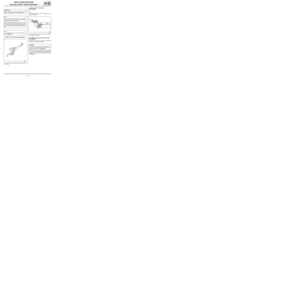
II - REMOVAL OPERATION FOR PART
CONCERNED
aRemove:
-the trim (1) ,
-the indicator (2) ,
-the windscreen trim piece.
aDisconnect the indicator.
aRemove:
-the bolts,
-the front wing.
REFITTING
I - REFITTING PREPARATIONS OPERATION
aIn addition, order the wing upper reinforcement and
mounting angle bracket.II - REFITTING OPERATION FOR PART
CONCERNED
aRefit:
-the front wing,
-the bolts.
aConnect the indicator.
aRefit:
-the windscreen trim piece,
-the indicator (2) ,
-the trim (1) .
III - FINAL OPERATION.
aRefit:
-the halogen headlight (see Halogen headlight:
Removal - Refitting) (MR 411, 80B, Headlights),
-the front bumper (see Front bumper: Removal -
Refitting) (MR 412, 55A, Exterior protection),
-the front wheel arch liner (see Front wheel arch
liner: Removal - Refitting) (MR 412, 55A, Exterior
protection).
121198